
Related Manuals for Kärcher BR 250 R


Summarization of Contents
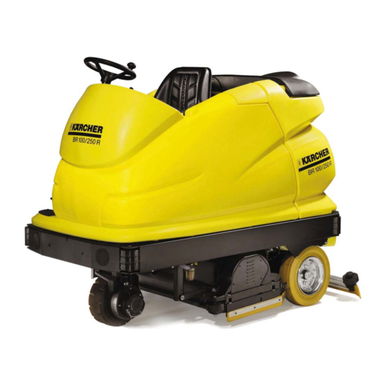
Equipment Features
Technical Features (BR/BD 100/250 R / BP)
Details technical specifications for the BR/BD 100/250 R model.
Technical Features (BR/BD 100/250 RI)
Details technical specifications for the BR/BD 100/250 RI model.
Technical Features (BR/BD 120/250 R, BR/BD 120/250 RI)
Technical specifications for BR/BD 120/250 R and RI models.
View from the Left-Hand Side
Diagram and labels for the machine's left-hand side view.
View from the Right-Hand Side
Diagram and labels for the machine's right-hand side view.
Rear View
Diagram and labels for the machine's rear view.
Technical Features
Wheel Hub Motor (M1)
Details the wheel hub motor, its components, and specifications.
Brush Head
Describes the brush head, its parts, and mounting.
Suction Beam
Explains the suction beam, its components, and adjustment.
Suction Motor (M4)
Details the suction motor, its function, and location.
Water System
Explains the water filter, pump, metering, and canister system.
Dirty Water Tank with Recycling Function (Optional)
Describes the dirty water tank and the optional recycling mode.
Control Panel
Overview of the machine's control panel and its buttons/indicators.
Program Switch (S9)
Details the functions of the 8-position program switch.
Seat Sensor (S10) and Distribution Box (EXT.X1)
Explains the seat sensor safety function and the distribution box.
Battery (Low-Maintenance) with Filling System
Details the battery, its filling system, and connections.
Battery Charger
Information about the battery charger and its operating instructions.
Side Brush (Optional)
Describes the optional side brush system and suspension.
Pre-Sweeper Unit (BR/BD 100/250 RI only)
Introduces the pre-sweeper unit specific to RI models.
Pre-Sweeper Unit, Parallelogram (Adjustment)
Details how to adjust the parallelogram for the pre-sweeper unit.
Pre-Sweeper Unit, Control Panel
Overview of the control panel for the pre-sweeper unit.
Unit Functions
Functional Diagram
Schematic showing the functional flow of the machine's systems.
Brush Head Mounting Parts
Details the components for mounting the brush head.
Brush System - Contact Pressure Adjustment
Explains how brush contact pressure is adjusted via the lifting motor.
Pre-Sweeper Unit Functional Diagram (BR/BD 100/250 RI only)
Functional diagram for the pre-sweeper unit on RI models.
Operator and Service Program Overview
Overview of operator functions and service program availability.
Operator Functions
Details operator and service technician functions, including test modes and setup menus.
Initial Operation and Information Menu REVISED
Step-by-step guide for initial operation and accessing the information menu.
Driving (Without Cleaning Functions) REVISED
Procedure for driving the machine without engaging cleaning functions.
Wet Scrubbing (With Suction)
Steps for performing wet scrubbing with suction.
Wet Scrubbing (Without Suction)
Steps for performing wet scrubbing without suction.
Suction (Without Scrubbing Mode)
Procedure for operating the machine in suction-only mode.
Polishing (Without Suction)
Steps for polishing the floor without suction.
Polishing (With Suction)
Steps for polishing the floor with suction.
Hand Cleaning with Wall-Ceiling-Floor Tool (Optional)
Instructions for hand cleaning with an optional tool.
Operator Functions - Manufacture Settings
Table detailing manufacture settings for operator functions.
Modular Electronic Control Circuits
Modular Electronic Control Circuits
Overview of the modular electronic control system and module networking.
Modular System BR/BD 100/250 R
Diagram showing the modular system configuration for the BR/BD 100/250 R.
Modular System BR/BD 100/250 R with Side Brush (Optional)
Diagram of the modular system with an optional side brush.
Modular System BR/BD 100/250 RI
Diagram showing the modular system configuration for the BR/BD 100/250 RI.
Emergency Operation (Driving) Using the Example of the BR/BD 100/250 R
Procedure for emergency driving operation.
Control Panel (View from Below) with Warning and Information Module (A0) and Head CPU Module (A1)
View of the control panel electronics, A0, and A1 modules.
Lifting Module (A4) and Accessories Module (A5)
Details of the lifting module (A4) and accessories module (A5).
Driving Module (A2) and Cleaning Module (A3)
Details of the driving module (A2) and cleaning module (A3).
Lifting Module (A4/1) (Optional) and Cleaning Module (A3/1) (Optional)
Details of optional lifting (A4/1) and cleaning (A3/1) modules.
Service Module (A9)
Description and scope of supply for the service module.
Basic Settings and Service Procedures
Access to the Test Mode (with Program Switch S9, Position 1)
Steps to access test mode with program switch in position 1.
Access to the Test Mode (with Program Switch S9, Position 2)
Steps to access test mode with program switch in position 2.
Current Measurement with Switching On/Off Function REVISED
Procedure for measuring current with on/off function in test mode.
Access to the Test Mode (with Program Switch S9, Position 3)
Steps to access test mode with program switch in position 3.
Access to the Test Mode (with Program Switch S9, Position 4)
Steps to access test mode with program switch in position 4.
Access to the Test Mode REVISED (with Program Switch S9, Position 5)
Steps to access test mode with program switch in position 5.
Accelerator Pedal Calibration
Procedure for calibrating the accelerator pedal.
Illuminated Symbol Test
Procedure for testing all illuminated symbols and LEDs.
Service-Operator Menu
Accessing and navigating the service-operator menu.
Access to the Test Mode ORIGINAL
Steps to access test mode (original version).
Test Mode - Drive Units ORIGINAL
Test mode procedures for drive units.
Test Mode - Lifting Motors ORIGINAL
Test mode procedures for lifting motors.
Test Mode - Calibration ORIGINAL
Test mode procedures for calibration.
Access to the Setup Menu REVISED
Steps to access the setup menu.
System Menu and Driving Module Parameters REVISED
System and driving module parameters within the setup menu.
Cleaning Module and Lifting Module Parameters REVISED
Cleaning and lifting module parameters within the setup menu.
Access to the Setup Menu ORIGINAL
Steps to access the setup menu (original version).
Access to the Setup Menu
Continuation of steps to access the setup menu.
System Menu and Driving Module Parameters ORIGINAL
System and driving module parameters (original version).
Cleaning Module and Lifting Module Parameters ORIGINAL
Cleaning and lifting module parameters (original version).
Save Changed Adjustable Parameters
Procedure for saving adjusted parameters.
Load Backup Operating Hours Counter
Procedure for loading backup operating hours.
Module Parameter Manufacture Settings
Table of manufacture settings for various modules.
Module Parameter - Manufacture Settings
Further details on manufacture settings for options.
Steering
Details the steering column, head, and wheel hub motor.
Lifting Motor - Suction Beam (M30)
Instructions for adjusting microswitches and maintaining the suction beam lifting motor.
Lifting Motor - Brush Head (M20)
Instructions for adjusting the brush head lifting motor and microswitches.
Brush Head - Maintenance Work
Procedures for replacing brush rollers, disc brushes, and drive belts.
Brush Head - Maintenance Work
Procedures for checking brush rollers, splash guards, and brush pattern.
Drive Sensor (B1)
Adjusting the drive sensor and its calibration.
Wheel Hub Motor Tyres (M1)
Checking and replacing carbon brushes in the wheel hub motor.
Wheel Hub Motor Tyres (M1)
Procedure for replacing the tyres on the wheel hub motor.
Magnet Brake (Y1)
Removing, checking, and adjusting the electromagnetic brake.
Magnet Brake (Y1)
Checking and setting the electromagnetic brake with the mounting plate.
Rear Wheel Brake
Instructions for adjusting the rear wheel brake.
Replacement Intervals
Table listing components and their recommended replacement intervals.
Troubleshooting
Troubleshooting Without Displays
Troubleshooting steps when the display shows no errors.
Unit Won't Start
Steps to troubleshoot when the unit fails to start.
Water Volume Too Low
Troubleshooting steps for insufficient water volume.
Suction Performance Too Low / Dirty Water Tank Overflows
Troubleshooting suction issues and tank overflows.
Troubleshooting With Displays
Troubleshooting procedures for errors displayed on the screen.
Structure of Warning Messages
Explanation of how warning messages are structured and displayed.
Meaning of the 3-Digit Error Code
Explanation of the 3-digit error code format and classes.
Module Clones (BR/BD 100/250 R/I)
Details on module clones for troubleshooting displayed errors.
Troubleshooting With Displays
General procedure for troubleshooting displayed faults.
Drive Module (A2) Error Messages
List of error messages related to the drive module (A2).
Drive Module (A2) Error Messages
Further list of error messages for the drive module (A2).
Drive Module (A2) Error Messages
Additional error messages for the drive module (A2).
Accessories Module (A5) Error Messages
List of error messages for the accessories module (A5).
Accessories Module (A5) Error Messages
Further error messages for the accessories module (A5).
Lifting Module (A4) and Cleaning Module (A3) Error Messages
Error messages for lifting (A4) and cleaning (A3) modules.
Lifting Module (A4) and Cleaning Module (A3) Error Messages
Further error messages for lifting (A4) and cleaning (A3) modules.
Lifting Module (A4) and Cleaning Module (A3) Error Messages
Additional error messages for lifting (A4) and cleaning (A3) modules.
Lifting Module (A4) and Cleaning Module (A3) Error Messages
Final error messages for lifting (A4) and cleaning (A3) modules.
Head CPU (A1) Error Messages
List of error messages related to the Head CPU module (A1).
Head CPU (A1) Error Messages
Further error messages for the Head CPU module (A1).
Head CPU (A1) Error Messages
Additional error messages for the Head CPU module (A1).
Error Memory
Overview of error memory and user messages.
Module Error Codes – Display Pattern
Explanation of module error code display patterns.
Significant Errors (Head CPU Module A1)
Details significant errors for the Head CPU module (A1).
Significant Errors (Drive Module A2)
Details significant errors for the Drive module (A2).
Significant Errors (Cleaning Module A3)
Details significant errors for the Cleaning module (A3).
Significant Errors (Lifting Module A4)
Details significant errors for the Lifting module (A4).
Significant Errors (Accessories Module A5)
Details significant errors for the Accessories module (A5).
Maintenance Work
Maintenance Work
Table of maintenance operations after working hours.
Maintenance Work
Additional maintenance operations for version RI and general checks.
Circuit Diagrams
Circuit Diagram 0.088-734.0 ORIGINAL, Head CPU (A1)
Circuit diagram for the Head CPU (A1) module.
Circuit Diagram 0.088-876.0 REVISED, Head CPU (A1)
Revised circuit diagram for the Head CPU (A1) module.
Circuit Diagram 0.088-734.0 ORIGINAL, 0.088-876.0 REVISED, Driving module (A2)
Circuit diagrams for the Driving module (A2).
Circuit Diagram 0.088-734.0 ORIGINAL, 0.088-876.0 REVISED, Cleaning module (A3)
Circuit diagrams for the Cleaning module (A3).
Circuit Diagram 0.088-734.0 ORIGINAL, 0.088-876.0 REVISED, Cleaning module - Pre-sweeper unit (A3/1)
Circuit diagrams for the Cleaning module - Pre-sweeper unit (A3/1).
Circuit Diagram 0.088-734.0 ORIGINAL, 0.088-876.0 REVISED, Lifting module (A4)
Circuit diagrams for the Lifting module (A4).
Circuit Diagram 0.088-734.0 ORIGINAL, 0.088-876.0 REVISED, Lifting module - Side brush (A4/1)
Circuit diagrams for the Lifting module - Side brush (A4/1).
Circuit Diagram 0.088-734.0 ORIGINAL, 0.088-876.0 REVISED, Lifting module - Pre-sweeper unit (A4/2)
Circuit diagrams for the Lifting module - Pre-sweeper unit (A4/2).
Circuit Diagram 0.088-734.0 ORIGINAL, 0.088-876.0 REVISED, Accessory module (A5)
Circuit diagrams for the Accessory module (A5).
Circuit Diagram 0.088-734.0 ORIGINAL, 0.088-876.0 REVISED, Listing
List of components used in the circuit diagrams.
Technical Specifications
Technical Specifications
Table listing unit types, unit numbers, circuit diagrams, and manuals.
Special Tools
Special Tools
List of special tools required for maintenance.
Tightening Torques
Tightening Torques
Specifies tightening torques for various components.
Need help?
Do you have a question about the BR 250 R and is the answer not in the manual?
Questions and answers