Lexicon MC-12HD User Manual
Digital controller
Hide thumbs
Also See for MC-12HD:
- Protocol manual (135 pages) ,
- Software upgrade instructions (10 pages) ,
- Supplementary manual (4 pages)
Table of Contents
Advertisement
Advertisement
Table of Contents
Troubleshooting

Related Manuals for Lexicon MC-12HD


Summary of Contents for Lexicon MC-12HD
- Page 1 MC-12HD Digital Controller User Guide...
-
Page 2: Important Safety Instructions
IMPORTANT SAFETY INSTRUCTIONS Read these instructions. 12. Only use attachments/accessories specified by the • Do not install the unit in an unventilated rack, manufacturer. or directly above heat-producing equipment Keep these instructions. such as power amplifiers. Observe the 13. Use only with the cart, stand, tripod, bracket, or Heed all warnings. - Page 3 Customer Service Telephone: 781-280-0300 Lexicon, Logic 7 and the L7 logo are registered trademarks of Harman International Industries, Inc. U.S. Patent Nos. D454,553; Sales Fax: 781-280-0495 D454,860; 5,796,844; 5,870,480 and other worldwide patents issued and pending. Lexicon LIVE is a trademark of Harman Interna-...
- Page 4 This document uses the term MC-12HD to refer to both the MC-12HD and MC-12HD Balanced digital controllers unless otherwise specified. This document uses the term DTS(-ES) to indicate that DTS-ES encoding may or may not be present in the input source.
-
Page 5: Table Of Contents
INPUT SELECT Parameter Settings ........3-21 ZONE2 & RECORD IN Parameter Settings ......3-23 Getting Started Speaker Setup ................. 3-26 About The MC-12HD ..............1-2 Setting Crossover Points ............3-26 Highlights ................1-4 Calibrating Speaker Distances & Output Levels ....... 3-38 Product Registration .............. - Page 6 Introduction Lexicon Troubleshooting & Maintenance Troubleshooting ................6-2 Routine Maintenance..............6-4 Restoring Factory default Settings..........6-5 Appendix Specifications................A-2 Declaration of Conformity ............A-4 Menu Tree.................A-5 Installation Worksheet ............A-21...
-
Page 7: Getting Started
Getting Started About The MC-12HD ..............1-2 Highlights ....................1-4 Product Registration ..............1-5 Installation Considerations............1-5 Remote Control Battery Installation ..........1-6... -
Page 8: About The Mc-12Hd
All Main Zone audio output connectors include 24-bit/96kHz D/A converters operating in dual differential mode. In In addition to Logic 7 and LIVE!, the MC-12HD is also equipped with addition, the MC-12HD Balanced includes balanced audio output Dolby Digital Surround EX, Dolby Pro Logic, Dolby Pro Logic II, connectors for all Main Zone and Zone 2 channels. - Page 9 5.1 analog audio input signals to digital signals, broadcast-quality component video switcher. In comparison, most allowing the MC-12HD to provide the benefits of precise digital standard-definition (SDTV) broadcasts have a resolution of 480i. signal processing without sacrificing signal integrity. Alternatively, Some DVD players and enhanced-definition (ED) digital TV stereo and 5.1 analog signals can bypass A/D conversion and...
-
Page 10: Highlights
• LOGIC 7 decoding • Auto switching between digital and • 3 trigger output connectors • LIVE! (Lexicon Intelligent Variable analog audio input connectors Environment) • Rear panel IR input connector • 24-bit/192kHz D/A converters for all •... -
Page 11: Product Registration
MC-12HD on a solid, flat, level surface such as a table or shelf. The MC-12HD can also be installed in a standard 19-inch... -
Page 12: Remote Control Battery Installation And Replacement
The batteries should be replaced as needed. Alkaline batteries, which last longer without leaking, are recommended. When battery power is low, the remote control enters a low-voltage condition, preventing it from operating the MC-12HD. When this occurs, replace the batteries. - Page 13 Basic Operation Front-Panel Overview ..............2-2 Rear-Panel Overview ..............2-6 Remote Control Overview ............2-11 Operation Considerations ............... 2-11 Main Menu .................... 2-12 Menu Navigation ................... 2-12 Menu Item Selection ................2-12 Command Bank Activation ..............2-14 Command Matrix .................. 2-15 About the Zones ..............
-
Page 14: Front-Panel Overview
Basic Operation Lexicon FRONT-PANEL OVERVIEW The MC-12HD is shown below. The MC-12HD Balanced is shown on page 2-4. The front panels are identical, but the MC-12HD Balanced has a larger chassis. 1. Standby Button 7. Zone 2 Input Selection Buttons 2. -
Page 15: Standby Button
Note: panel power switch is powered off. When standby mode is deacti- vated, all MC-12HD zones that were active during the last session When MC-12HD output levels are properly calibrated, the +0dB volume are reactivated. The red LED in the standby button lights to indicate level setting corresponds to the THX reference level (75dB). -
Page 16: Basic Operation
Basic Operation Lexicon FRONT-PANEL OVERVIEW (continued) The MC-12HD Balanced, shown below, has a larger chassis than the MC-12HD, shown on page 2-2. Otherwise, they are identical. 5 MODE BUTTONS Use the Mode buttons to scroll to the previous and next available Mode button to scroll upward through available listening modes. -
Page 17: Main Zone Input Selection Buttons
12 MUTE BUTTON 7 ZONE 2 INPUT SELECTION BUTTONS Press the Mute button to mute the MC-12HD Main Zone volume; "MUTE ON appears in the on-screen and front panel displays. Press Selects the input in Zone 2. When an input is selected, an amber the Mute button again to restore the MC-12HD volume to its LED lights on the corresponding input selection button. -
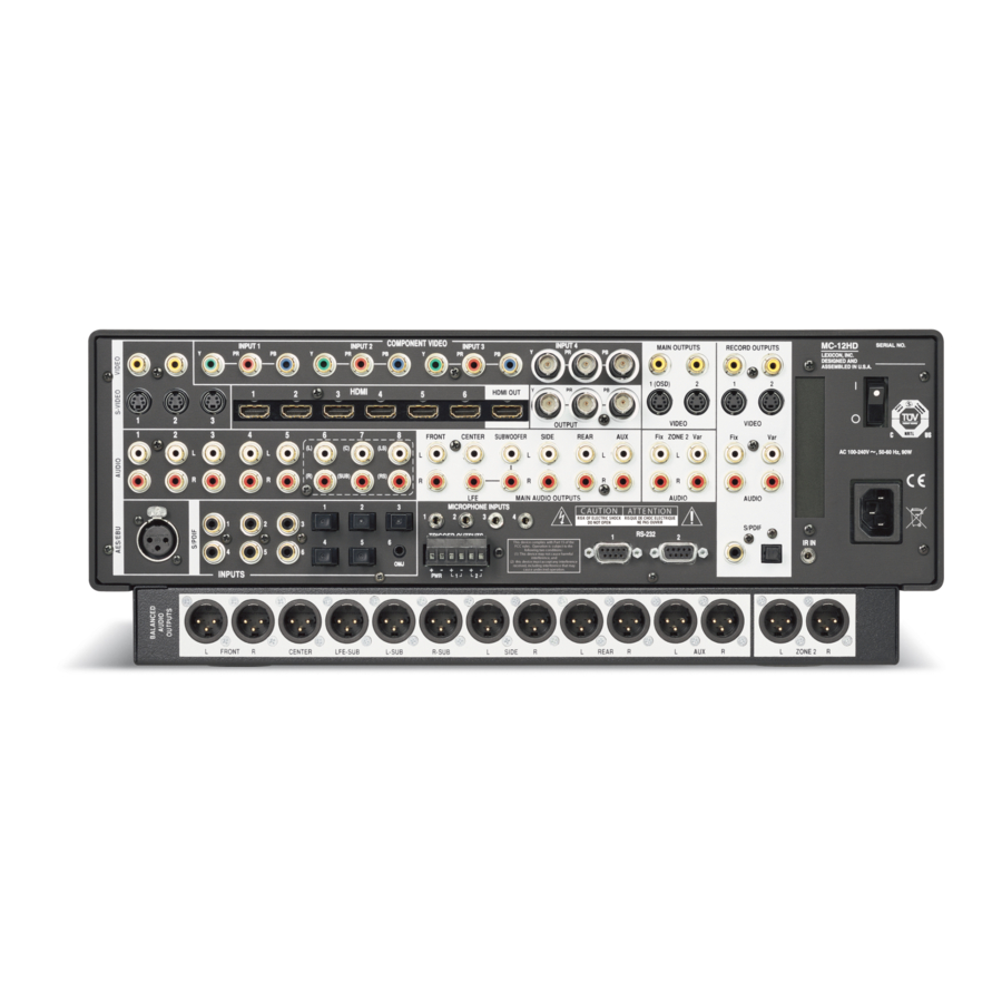
Page 18: Rear-Panel Overview
REAR-PANEL OVERVIEW The MC-12HD is shown below. The MC-12HD Balanced, shown on page 2-8, includes balanced audio output connectors for the Main Zone and Zone 2. Otherwise both models are identical. The numbers in the rear-panel illustrations correspond with the numbered items. -
Page 19: Hdmi Output Connector
Note: 16. Microphone Input Connectors A DVI (Digital Visual Interface) device can be connected to the MC-12HD through a DVI-to-HDMI cable or adaptor. DVI carries video 17. Trigger Output Connectors but no audio. 18. Balanced Audio Output Connectors (see page 2-8) 19. - Page 20 Basic Operation Lexicon REAR-PANEL OVERVIEW (continued) The MC-12HD is shown on page 2-6. The MC-12HD Balanced, shown below, includes balanced audio connectors for the Main Zone and Zone 2. Otherwise both models are identical. FRONT CENTER SUBWOOFER SIDE REAR ZONE 2 Caution! Never make or break connections to the MC-12HD unless the MC-12HD and all associated components are powered off.
-
Page 21: Zone 2 Audio Output Connectors
12 AC INPUT CONNECTOR Provide analog audio output in Zone 2. Two sets of stereo Provides power to the MC-12HD through the supplied power cord. connectors labeled Audio L/R are available. The connectors labeled Fix pass audio at fixed output levels. The connectors labeled Var... - Page 22 The PWR connector – the power trigger output connector – When a 5.1-channel analog audio source is present in the Main cannot be configured. It is activated when the MC-12HD is Zone, input signals are sent to the Main Zone audio output activated, and deactivated when the MC-12HD is deactivated.
-
Page 23: Remote Control Overview
IR receiver. • For optimal performance, position the remote control at a 30 degree angle no more than 17 feet (5m) from the MC-12HD. Placing the MC-12HD inside a smoked glass cabinet will reduce the remote control range. •... -
Page 24: Main Menu
The highlighted menu item is displayed on the MC-12HD front-panel. MENU ITEM SELECTION 2. - Page 25 Basic Operation MC-12HD MENU OPTIONS displayed beneath the parameter name in the on-screen and front-panel displays. Selecting a menu option opens another menu within the menu 2. When the desired setting appears beneath the parameter structure. For example, selecting SETUP from the MAIN MENU opens...
-
Page 26: Command Bank Activation
MC-12HD received a command. A “Z” appears to indicate Zone 2. An “R” appears to The command bank selection buttons themselves do not send indicate the Record Zone. -
Page 27: Command Matrix
Record Zone Shift Activates and deactivates standby mode when the MC-12HD rear panel power switch is in the on position. When standby mode is activated, pressing the standby button deactivates standby mode and activates the MC-12HD, including all zones that were activated during the previous operating session. - Page 28 Basic Operation Lexicon Button Main Zone Zone 2 Record Zone Shift Selects the SAT input for Selects the SAT input for Selects the SAT input for Sets the AUDIO the Main Zone. Zone 2. the Record Zone. CONTROLS menu LOUDNESS parameter to OFF.
- Page 29 Main Zone input source. connector labeled 1 connector labeled 2 MC-12HD is powered Scrolling occurs in the when the connector is when the connector is on with the rear panel order shown on the...
- Page 30 Basic Operation Lexicon Button Main Zone Zone 1 Record Zone Shift Displays the Main Zone Displays the Zone 2 Displays the Record Opens and closes the status menu for the line status for 2 line status for 2 Zone two line status current input source.
- Page 31 Basic Operation MC-12HD Button Main Zone Zone 1 Record Zone Shift Selects the THX mode Reserved for possible Reserved for possible Activates the 5.1 THX family for the current future expansion. future expansion. ULTRA2, 5.1 THX SurEX, input source. or 5.1 THX listening...
-
Page 32: About The Zones
The MC-12HD can process input sources in three 48kHz. When the source on the HDMI connector is copy- zones at the same time. For example, the MC-12HD can play a DVD protected DVD-Audio, no digital audio is output, but analog in the Main Zone, while playing a CD in Zone 2, while sending audio is still output. -
Page 33: Status Menus
Basic Operation MC-12HD ZONE 2 TWO-LINE STATUS STATUS MENUS Opens on the on-screen and front panel DVD1 The STATUS menu contains parameters that provide information displays whenever the Zone 2 status ZONE 2 -34dB about the current input source and listening mode. Status menus are changes. - Page 34 Basic Operation Lexicon 4. Press the STAT button to close the STATUS menu. In some cases, you must press STAT twice in succession to close the HDMI STATUS > S D STATUS D STATUS > S STATUS menu. HDMI CONNECTOR...
-
Page 35: Status Menu Level Meters
Basic Operation MC-12HD STATUS MENU LEVEL METERS STATUS MENU DESCRIPTIONS Most STATUS menus contain level meters that indicate fluctuating The table beneath each description lists the default and possible input levels in the front left (L), center (C), front right (R), surround left settings for each parameter. - Page 36 Basic Operation Lexicon 2CH STATUS D STATUS Provides information about 2-channel input sources. Features L and Provides information about Dolby Digital input sources. Features L, R level meters. C, R, SL, SR and LFE level meters. Parameter Possible Settings Parameter...
- Page 37 SAMPLE RATE 44.1kHz, 48kHz, 88.2kHz, 96kHz The only possible sample rate for 5.1 analog sources is 96kHz, as they are converted to 96kHz PCM at the MC-12HD input (when MAIN ADVANCED ANALOG BYPASS is set to OFF). See “Status Menu Parameter Descriptions” on page 2-28 for detailed information.
- Page 38 Basic Operation Lexicon 5.1a BYPASS STATUS 2CH BYPASS STATUS Provides information about 5.1-channel input sources when the Provides information about 2-channel analog input sources when MAIN ADV menu ANALOG BYPASS parameter is set to ON. the MAIN ADV menu ANALOG BYPASS parameter is set to ON.
- Page 39 Basic Operation MC-12HD DIGITAL STATUS LIVE! STATUS Provides information about digital input sources for which a sample Provides information about LIVE! input sources. Includes L and R rate is detected, but no audio is present in the input signal. level meters.
-
Page 40: Status Menu Parameter Descriptions
DIALOG OFFSET parameter AUDIO FMT DD, DTS, PCM, --- indicates the amount of adjustment the MC-12HD makes to Displays the type of audio present at the selected active digital normalize dialog to -27dBFS. - Page 41 Basic Operation MC-12HD 5.1-channel Dolby Digital source recorded without Dolby Digital MODE Surround EX encoding is detected. The MC-12HD cannot automat- Indicates the activated listening mode (e.g., L7 FILM). ically detect Dolby Digital Surround EX encoding in non-flagged input sources.
-
Page 43: Table Of Contents
Setup Setup ..................3-2 Input Setup ................3-4 Changing Input Names ................3-5 Assigning HDMI, Audio and Video Input Connectors ....... 3-7 Selecting Preferred Listening Modes ............3-14 Configuring Advanced Input Settings ............. 3-19 INPUT SELECT Parameter Settings ............3-21 ZONE2 & RECORD IN Parameter Settings ..........3-23 Speaker Setup ................3-26 Setting Crossover Points ................. -
Page 44: Setup
Setup Lexicon SETUP Selecting SETUP from the MAIN MENU opens the SETUP menu. REAR PANEL CONFIG SETUP REAR PANEL CONFIG MAIN MENU SETUP Opens the REAR PANEL CONFIG menu, to configure the analog audio input MODE ADJUST INPUTS connectors as eight stereo connectors or as five stereo and one 5.1-channel... - Page 45 Setup MC-12HD LOCK OPTIONS SETUP LOCK OPTIONS Opens the LOCK OPTIONS menu, to protect MODE ADJUST, AUDIO CONTROLS and SETUP menu branch settings from accidental changes. See “LOCK OPTIONS” on page 3-75 for more information. LIVE! CALIBRATION SETUP LIVE! CALIBRATION Opens the LIVE! CALIBRATION menu, to perform the necessary calibration before using the LIVE! modes.
-
Page 46: Input Setup
Setup Lexicon INPUT SETUP SETUP INPUTS (INPUT) INPUT SETUP Selecting the SETUP menu INPUTS option prompts the selection of a desired input (e.g., DVD1). Selecting an input opens the corresponding INPUT SETUP menu, which changes input names, assigns audio and video input connectors, selects preferred listening modes, and configures advanced Main Zone, Zone 2, and Record Zone settings. -
Page 47: Changing Input Names
Setup MC-12HD CHANGING INPUT NAMES Selecting the INPUT SETUP menu NAME parameter opens the INPUT NAME menu, to customize or restore the factory-default name of the selected input. Factory-default input names correspond to front-panel and remote control input selection button labels. - Page 48 Setup Lexicon CHANGING INPUT NAMES (continued) 4. Repeat step 3 to enter all characters in the new name. When the The custom input name appears in the on-screen and front-panel input name you want is displayed, press the arrow button to displays.
-
Page 49: Assigning Hdmi, Audio And Video Input Connectors
ASSIGNING HDMI, AUDIO AND VIDEO INPUT CONNECTORS The MC-12HD has 12 inputs to which any (depending on compatibility) of its 6 HDMI, 13 digital audio, 8 analog audio, 2 composite video, 3 S-video, or 4 component video input connectors can be assigned. The table below indicates the INPUT SETUP menu parameters that can be used to assign audio and video input connectors. - Page 50 Setup Lexicon ASSIGNING HDMI, AUDIO AND VIDEO INPUT CONNECTORS (continued) The following table shows the behavior of the MC-12HD relating to the HDMI inputs. Inputs Outputs HDMI Digital In HDMI Output Analog Audio Outputs HDMI-1 to 6 HDMI AUDIO HDMI video...
- Page 51 Setup MC-12HD DIGITAL IN When no analog audio input connector is assigned, the MC-12 HDMI AUDIO, COAX-1 TO 6, OPTICAL-1 TO 6, automatically sets the: AES/EBU, NONE • MAIN ADV menu INPUT SELECT parameter to DIGITAL DVD1 SETUP INPUTS DIGITAL IN •...
- Page 52 Lexicon ASSIGNING HDMI, AUDIO & VIDEO INPUT CONNECTORS (continued) ANALOG IN When no digital audio input connector is assigned, the ANALOG-1 TO 8, 5.1 ANLG (6-8), LIVE!, NONE MC-12HD automatically sets the: SETUP INPUTS DVD1 ANALOG IN • MAIN ADV menu INPUT SELECT parameter to ANALOG •...
- Page 53 ANALOG BYPASS parameter is set to OFF) analog audio input levels for the selected AUTO ON, OFF input. Analog audio sources have a wide range of levels. To compensate, the MC-12HD allows independent input level SETUP INPUTS DVD1 ANGL IN LVL AUTO adjustment of each stereo analog audio input connector.
- Page 54 MANUAL parameter. When the AUTO parameter is ON, the MC-12HD will not make adjustments that exceed the ANLG IN LVL menu MANUAL parameter When AUTO GAIN is set to OFF setting.
- Page 55 Setup MC-12HD ANLG IN LVL menu level meters indicate input levels for both analog Note: and digital audio sources. However, ANLG IN LVL menu input level • Composite video output connectors are available only when a adjustments only affect 2-channel (or 5.1-channel sources when the composite video source is present.
-
Page 56: Selecting Preferred Listening Modes
Selects a preferred listening mode for Dolby Digital sources The MC-12HD allows five preferred listening modes for each Main Selects a preferred listening mode for DTS(-ES) sources Zone input: one listening mode each for 2-channel, Dolby Digital, DTS(-ES), 5.1-multichannel, and MIC (LIVE!) sources. - Page 57 MC-12HD When a preferred listening mode is selected, that listening mode is the MC-12HD is configured for seven main output channels and automatically activated whenever a new input is selected or an source material with specific encoding is played. All Dynamic appropriate input source is present.
- Page 58 When a preferred listening mode is set When the MC-12HD is set to use a preferred listening mode for a and a dynamic listening mode (or mode that does not appear in the...
- Page 59 When the D parameter is set to USE LAST: the MC-12HD is set to standby. • The MC-12HD uses the listening mode that was activated the 2-CH last time a Dolby Digital source was present. SETUP INPUTS...
- Page 60 LIVE! source. The MC-12HD automatically activates the preferred listening mode when the ANALOG IN selection is LIVE! When the MIC parameter is set to USE LAST the MC-12HD uses the listening mode that was activated the last time a MIC source was present.
-
Page 61: Configuring Advanced Input Settings
RECORD IN DIGITAL ANLG DMIX RECORD ADVANCED MAIN ADVANCED The MC-12HD allows the assignment of one digital and one analog audio input connector for each input. The table below indicates the DVD1 MAIN ADVANCED SETUP INPUTS INPUT SETUP menu parameters that can be used to control the... - Page 62 S-video and AUTO settings. switcher, enabling compatible display devices to automatically switch between anamorphic and non-anamorphic display modes. ANALOG BYPASS ON, OFF When OFF, the MC-12HD prevents anamorphic video input signals SETUP INPUTS DVD1 MAIN ADVANCED ANALOG BYPASS...
-
Page 63: Input Select Parameter Settings
INPUT SELECT PARAMETER SETTINGS DIGITAL ANALOG AUTO The MC-12HD sends the digital audio from The MC-12HD sends the analog audio from The MC-12HD toggles between sending digital or the assigned input to the Main Zone audio the assigned input to the Main Zone audio analog audio input to the Main Zone audio output output connectors. - Page 64 • The S-VIDEO OSD (4:3) parameter is OFF. When set to NORMAL, the MC-12HD will not mute when silence is • An anamorphic video input signal is present. detected. This setting is appropriate for most sources.
-
Page 65: Zone2 & Record In Parameter Settings
DMIX (Downmix) The MC-12HD passes digital audio The MC-12HD passes analog audio The MC-12HD passes a downmixed version of Main Zone audio to the from the assigned input to the Zone 2 from the assigned input to the Zone 2 Zone 2 or Record Zone audio output connectors. - Page 66 Setup Lexicon CONFIGURING ADVANCED INPUT SETTINGS (continued) RECORD ADVANCED ANLG IN LVL -18 to +12dB SETUP INPUTS DVD1 RECORD ADVANCED SETUP INPUTS DVD1 RECORD ADVANCED ANLG IN LVL Opens the RECORD ADV menu, which configures advanced Record Allows adjustment of analog audio input levels for input signals sent to the Record Zone digital audio output connectors.
- Page 67 If the downmixed audio is coming from the HDMI input, and the Prevents recording device feedback loops. When BLOCKED is content is HDCP-encoded, the sample rate is limited to no more selected, the MC-12HD blocks the Record Zone audio output than 48kHz. connectors to prevent feedback loops. However, video input signals are still passed to the Record Zone video output connectors.
-
Page 68: Speaker Setup
Note: SETUP SPEAKERS The MC-12HD Balanced also includes 10 balanced Main Zone audio output connectors labeled Front L/R, Center, LFE, Subwoofer L/R, Side Selecting the SETUP menu SPEAKERS option opens the SPEAKER L/R, and Rear L/R. Two additional audio output connectors labeled Aux SETUP menu, which configures the Main Zone audio output L/R are provided for future expansion. - Page 69 Setup MC-12HD MAIN MENU SETUP SPEAKER SETUP CUSTOM SETUP CROSSOVER SETUP CUSTOM SETUP SETUP FRONT L/R 80 Hz INPUTS SET CROSSOVERS CUSTOM SETUP 40 Hz MODE ADJUST INPUTS CENTER 80 Hz SPEAKERS CHECK MICROPHONES THX SETUP 60 Hz AUDIO CONTROLS...
- Page 70 Setup Lexicon SETTING CROSSOVER POINTS (continued) High-pass Filter Low-pass Filter Low-pass filters attenuate high frequencies at 24dB per octave. The curves in the graph High-pass filters attenuate low frequencies at 24dB per octave. The curves in the graph above indicate the frequency response of each crossover setting. From left to right, the above indicate the frequency response of each crossover setting.
- Page 71 80Hz 80Hz 80Hz 80Hz 80Hz THX SPEAKER SETUPS When a THX speaker setup is selected, the MC-12HD applies a THX SETUP SPEAKERS SET CROSSOVERS THX SETUP 80Hz crossover point with a 12dB-per-octave filter to the Front L/R, Center, Side L/R, and Rear L/R output connectors. The MC-12HD...
- Page 72 Setup Lexicon SETTING CROSSOVER POINTS (continued) SPEAKER SETUP PARAMETERS SETUP SPEAKERS SET CROSSOVERS CUSTOM SETUP SETUP SPEAKERS SET CROSSOVERS THX SETUP The table below indicates the speaker setup parameters for config- one menu, the corresponding parameter setting is automatically uring all possible settings for speaker setup parameters in the adjusted on the other menu.
- Page 73 Setup MC-12HD CUSTOM SETUP SETUP CUSTOM SETUP CROSSOVER SETUP MAIN MENU SPEAKER SETUP FRONT L/R 40Hz INPUTS CUSTOM SETUP 40 Hz SET CROSSOVERS MODE ADJUST CENTER 60Hz SPEAKERS THX SETUP 60 Hz CHECK MICROPHONES AUDIO CONTROLS SIDE L/R 60Hz REAR PANEL CONFIG...
- Page 74 • Select FULL + SUB to send a full-range signal to the center speakers. The MC-12HD will redirect side channel signals to the speaker and duplicate bass frequencies to the SUB L/R outputs. Rear L/R output connectors. If the REAR L/R parameter is also...
- Page 75 • Select NONE when the speaker setup does not include rear speakers. The MC-12HD then redirects rear channel signals to the Side L/R output connectors. If the SIDE L/R parameter is also set to NONE, surround channel signals are sent to the Front L/R output connectors.
- Page 76 Select STEREO if the speaker setup includes two subwoofers. is applied to the SUBWOOFER L/R output connectors, and the The MC-12HD sends low frequency front left, center, and SUB L/R parameter cannot be adjusted. surround left channel signals to the SUBWOOFER L output...
- Page 77 Setup MC-12HD 5.1mc BYPASS listening mode is activated. In this instance, SETUP SPEAKERS SET CROSSOVERS THX SETUP configure the speaker setup with the associated DVD-A/SACD player to redirect low frequency signals. When a THX speaker setup is selected, the LFE information is redirected to the SUBWOOFER L/R output connectors, and the LFE parameter cannot be adjusted.
- Page 78 Setup Lexicon SETTING CROSSOVER POINTS (continued) THX ULTRA2 SUB Note: ON, OFF BGC compensates for increased bass energy that is caused by the SETUP SPEAKERS SET CROSSOVERS CUSTOM SETUP ULTRA2 SUB proximity of the speakers to the listening room walls.
- Page 79 Setup MC-12HD You can use the remote control 7/5 button to toggle between 7- and 5-channel playback. When you use the 7/5 button, the MC- 12HD automatically: • Activates ASA processing during 7-channel playback. • Deactivates ASA processing during 5-channel playback.
-
Page 80: Speaker Calibration Parameters
CALIBRATING SPEAKER DISTANCES & OUTPUT LEVELS The MC-12HD offers both automatic and manual calibration of speaker distances and output levels. Calibration helps to ensure accurate output signal arrival time and level at the primary listening position. However, it is not a substitute for proper speaker placement. - Page 81 Determines the unit of measurement in which speaker distances are calculated on ALL speaker distance menus. When FEET is selected, the MC-12HD calculates speaker distances in feet. When METERS is selected, the MC-12HD calculates speaker distances in meters. When the UNITS parameter setting is adjusted, the MC-12HD automatically adjusts speaker distances to the closest available value in the selected unit of measurement.
-
Page 82: Automatic Calibration
Setup Lexicon AUTOMATIC CALIBRATION The MC-12HD offers automatic calibration of speaker distances, output levels, or both. The table below indicates available automatic calibration options. A successful microphone check is required before automatic calibration can be performed. Automatic Options Details MICROPHONE CHECK •... - Page 83 • The microphone wires also require careful handling. Do not sharply bend the wires or place objects on them. 1. Make sure the MC-12HD is powered off OR in standby mode. • Never make or break microphone input connections unless 2.
- Page 84 Setup Lexicon AUTOMATIC CALIBRATION (continued) POSITIONING THE MICROPHONES FOR THE MICROPHONE CHECK Refer to the microphone placement examples that begin below to position the microphones for the microphone check. PROPER microphone positioning for the microphone check During the microphone check, position...
- Page 85 Setup MC-12HD IMPROPER microphone positioning for the microphone check During the microphone check, do not: 7 Separate the microphones 7 Scatter the microphones throughout the listening space 7 Obstruct the line-of-sight path between the micro- Rear phones and the speakers...
- Page 86 2. The first CHECK MICROPHONES screen opens in the on-screen display, indicating the importance of proper microphone • The MC-12HD outputs calibration noise signals between 55 placement to achieve accurate automatic calibration results. and 95dB, beginning with 55dB and increasing in 5dB incre- 3.
- Page 87 Setup MC-12HD check. To do this, the MC-12HD sends alternating calibration 4. Press the arrow buttons to highlight the desired noise signals to the front left and right speakers. microphone parameter. The MC-12HD refers to the micro- phones according to the input connector to which the The MC-12HD uses the calibration noise signal to eliminate microphone is connected.
- Page 88 The MC-12HD did not detect the micro- • Examine microphone input connections to ensure that the microphones are properly con- (MICROPHONE) nected to the MC-12HD and that microphone cable plugs are fully inserted for a solid connec- phone during the silence check. NOT DETECTED tion.
- Page 89 Microphone single listening position. The microphones are Center positioned as close together as possible in a single listening position, allowing the MC-12HD to calibrate Subwoofer optimal speaker distances and output levels for that Front Right position.
- Page 90 Each micro- Front Left phone is positioned in a single listening position within Microphone a single row, allowing the MC-12HD to calibrate Center optimal speaker distances and output levels for that row at the expense of a single listening position. Subwoofer...
- Page 91 Each Microphone microphone is positioned in a single listening position Center within rows, allowing the MC-12HD to calibrate optimal speaker distances and output levels for a Subwoofer larger listening area at the expense of a single listening position.
- Page 92 Front Right floor along the perimeter of the listening space, making it difficult for the MC-12HD to calibrate optimal speaker distances and output levels for the actual listening positions. To fine-tune individual speaker distances and output levels, refer to the MANUAL CALIBRATION section that begins on page 3-57. You should also configure the BASS PEAK LIMITERS param- eter settings.
- Page 93 Setup MC-12HD IMPROPER microphone positioning for automatic calibration During the automatic calibration, do not: 7 Arrange the microphones along the perimeter of the listening positions or space 7 Position the microphones at spots where the listeners’ heads will not be positioned...
-
Page 94: Performing Automatic Calibration
The following AUTO SPEAKER SETUP messages display on-screen before automatic calibration begins: • The !CAUTION! HIGH AUDIO LEVELS message indicates that the MC-12HD generates loud calibration noise signals during automatic calibration. • The TEST WILL BEGIN IN display notifies you that automatic calibration will begin in 10 seconds. The primary reason for the 10 second delay is to give you time to leave the listening space before automatic calibration begins. - Page 95 MC-12HD calculates a distance for the corresponding speaker. As it finishes each parameter, the MC-12HD enters the calibrated value or an ERROR message to the right of the parameter label.
- Page 96 6.0ft SIDE LEFT -4.5dB SIDE LEFT 4.5ft MONO SUB MONO SUB When the MC-12HD is finished calibrating SUB RIGHT SUB RIGHT speaker distances and output levels, the AUTO SPEAKER SETUP screen displays, indicating the results for each calibration procedure. If there was a DISTANCES calibration...
- Page 97 Setup MC-12HD STEP DISTANCES DISTANCES & LEVELS LEVELS SET DISTANCES AUTO DISTANCES AUTO SPEAKER SETUP AUTO DISTANCES* SET LEVELS AUTO LEVELS AUTO DISTANCES FRONT LEFT 12.0ft DISTANCES FRONT LEFT 12.0ft AUTO LEVELS FRONT LEFT -2.0dB ORIGINAL DISTANCES CENTER 10.5ft LEVELS...
- Page 98 3-42 to 3-46 to confirm that the microphones are appropriately positioned for automatic calibration. • Examine microphone input connections to ensure that the microphones are properly con- nected to the MC-12HD and that microphone cable plugs are fully inserted for a solid connec- tion. The microphones did not detect calibra- •...
-
Page 99: Manual Calibration
Setup MC-12HD MANUAL CALIBRATION SETUP SPEAKERS MANUAL Selecting the SPEAKER SETUP menu MANUAL option displays the MANUAL SPEAKER SETUP menu, to manually calibrate speaker distances and output levels. The table below indicates available manual calibration options. MAIN MENU SETUP SPEAKER SETUP... - Page 100 Setup Lexicon MANUAL CALIBRATION (continued) PERFORMING MANUAL SPEAKER DISTANCE CALIBRATION SETUP SPEAKERS MANUAL SPEAKER DISTANCES Selecting the MANUAL SPEAKER SETUP menu SPEAKER DISTANCES option displays the SPEAKER DISTANCES menu, to manually calibrate speaker distances. SETUP MAIN MENU SPEAKER SETUP MANUAL SPEAKER SETUP...
- Page 101 Setup MC-12HD PERFORMING MANUAL OUTPUT LEVEL CALIBRATION SETUP SPEAKERS MANUAL LEVELS CALIBRATION Selecting the MANUAL SPEAKER SETUP menu LEVELS CALIBRATION option displays the LEVELS CALIBRATION menu to manually calibrate output levels. Note the following: • You should use a Sound Pressure Level (SPL) meter to manually •...
- Page 102 During the internal noise test, the MC-12HD sends calibration noise next parameter, causing the MC-12HD to send the calibration signals to each speaker in the order shown on the SPEAKER LEVEL noise signal to both speakers.
- Page 103 Selecting the LEVELS CALIBRATION menu EXTERNAL NOISE TEST Note: option opens the SPEAKER LEVEL ADJUST menu shown on When the external noise test begins, the MC-12HD automatically sets page 3-59, which manually calibrates output levels. volume level to +0dB. Avoid adjusting the master volume level while the test is in progress to achieve THX reference levels.
- Page 104 Subwoofer L/R and LFE connectors. This menu also sets amplitude limits on low frequency signals redirected to other Main Zone audio output connectors. The MC-12HD is equipped with an internal limiter to prevent low frequency signals from exceeding a designated output level.
- Page 105 Setup MC-12HD CAL NOISE L/R LIMIT ADJ ON, OFF 75 to 120dB SETUP SPEAKERS MANUAL LEVELS CALIBRATION BASS PEAK LIMITERS SETUP SPEAKERS MANUAL LEVELS CALIBRATION BASS PEAK LIMITERS L/R LIMITER ADJ CAL NOISE Determines whether bass peak limiters are set with an internal or Specifies the output level restriction applied to the Subwoofer L/R external calibration source.
-
Page 106: Rear Panel Configuration
BASS PEAK LIMITERS 1. Select the LFE LIMIT ADJ parameter. LFE LIMITER ADJ The parameter initially sets to 75dB. Specifies the output level restriction the MC-12HD applies to the 2. Press the arrow button to change the parameter LFE output connector. - Page 107 Setup MC-12HD 5 STEREO & 5.1 ANLG SETUP REAR PANEL CONFIG 5 STEREO & 5.1 ANLG Select the 5 STEREO & 5.1 ANLG option to configure the analog audio input connectors as five stereo and one 5.1-channel connectors. When 5 STEREO & 5.1 ANLG is selected: •...
-
Page 108: Display Setup
A/V SYNC DELAY OFF, 1 to 60ms the custom unit name scrolls across the on-screen and front panel displays whenever the MC-12HD is activated. When OFF is selected, CUSTOM NAME ON, OFF the custom unit name does not scroll across the on-screen and... - Page 109 Opens the EDIT CUSTOM NAME drop-down menu shown above, 3. Use the following remote control commands to enter a unit which can be used to create a custom unit name. The factory name: default unit name is MC-12HD. • Press the arrow button to change the character above the cursor.
-
Page 110: On-Screen Display
Setup Lexicon ON-SCREEN DISPLAY SETUP DISPLAYS ON-SCREEN DISPLAY The ON-SCREEN DISPLAY option opens the ON-SCREEN DISPLAY menu, to customize the on-screen display. MAIN MENU SETUP DISPLAY SETUP ON-SCREEN DISPLAY ALWAYS ON 2 SECONDS INPUTS MODE ADJUST ON-SCREEN DISPLAY STATUS 2 SECONDS... - Page 111 The FORMAT parameter has no effect on the component video output Record Zone connector. Shift BACKGROUND ON, OFF * No letter appears when the MC-12HD receives a command from the Main Zone com- mand bank, even if the REMOTE STATE parameter is set to ON. SETUP DISPLAYS ON-SCREEN DISPLAY BACKGROUND Determines the on-screen display background.
-
Page 112: Front Panel Display
Setup Lexicon FRONT PANEL DISPLAY SETUP DISPLAYS FRONT PANEL DISPLAY Opens the FRONT PANEL DISPLAY menu, to customize the front panel display. MAIN MENU SETUP DISPLAY SETUP FRONT PANEL DISPLAY ALWAYS ON 2 SECONDS MODE ADJUST INPUTS ON-SCREEN DISPLAY STATUS... -
Page 113: Volume Control Setup
Zone 2 is activated. When LAST LVL is selected, ZONE PWR ON -30dB LAST LVL, -80 to +12dB the MC-12HD sets Zone 2 volume level to the last volume level that REC PWR ON -30dB LAST LVL, -80 to +12dB was selected in Zone 2 during the previous operating session. - Page 114 Sets the Record Zone volume level for the output connector labeled Var to the selected value when the Record Zone is activated. When LAST LVL is selected, the MC-12HD sets Record Zone volume level to the last volume level that was selected in the Record Zone during the previous operating session.
-
Page 115: Trigger Setup
PLII + The TRIGGERS option prompts you to select trigger output connector 1 or 2. The PLII MOVIE MC-12HD includes three 12V DC trigger output connectors labeled PWR (power), 1, and PLII MUSIC PL + 2. The PWR connector cannot be configured because its trigger output connector is... - Page 116 Setup Lexicon TRIGGER SETUP (continued) REMOTE ONLY Note the following: ON, OFF SETUP TRIGGER 2 REMOTE ONLY TRIGGERS TRIGGER 1 • Trigger output connectors can be associated with individual Main Zone inputs and listening modes. Configures the selected trigger output connector for remote operation.
-
Page 117: Lock Options
Setup MC-12HD LOCK OPTIONS SETUP LOCK OPTIONS Displays the LOCK OPTIONS menu, which protects MODE ADJUST, AUDIO CNTRL LOCKED, UNLOCKED AUDIO CONTROLS, and SETUP menu branch parameter settings SETUP LOCK OPTIONS AUDIO CNTRL from accidental changes. Protects AUDIO CONTROLS menu branch settings from accidental LOCK OPTIONS changes. -
Page 118: Live! Calibration
LIVE! requires 2 microphones, available in a kit from your authorized 1. Make sure the MC-12HD is powered off or in standby mode. Lexicon dealer. (If you already own the Lexicon 4-microphone kit, 2. - Page 119 Setup MC-12HD POSITIONING THE MICROPHONES FOR LIVE! Refer to the microphone placement examples below to position the microphones for LIVE! PROPER microphone positioning for LIVE! Position the microphones: 3 On or near opposite side walls 3 Approximately halfway between the front and...
- Page 120 Setup Lexicon LIVE! CALIBRATION (continued) IMPROPER microphone positioning for LIVE! When positioning the microphones, do not: 7 Place the microphones on the front or rear walls 7 Place the microphones near the floor or ceiling Rear Left 7 Obstruct the microphones with furniture or other...
- Page 121 The !CAUTION! HIGH AUDIO LEVELS message indicates that the • SIGNAL TOO LOW MC-12HD generates loud calibration noise signals during LIVE! cali- Indicates that the microphones failed to pick up sufficient cali- bration. Press the arrow button to begin calibration.
- Page 123 Audio Controls Audio Controls ................4-2...
- Page 124 Audio Controls Lexicon AUDIO CONTROLS Selecting the MAIN MENU AUDIO CONTROLS option opens the AUDIO CONTROLS menu, to customize the Main Zone, Zone 2, and Record Zone audio output connectors. MAIN MENU AUDIO CONTROLS BASS +0.0dB MODE ADJUST TREBLE +0.0dB...
- Page 125 Audio Controls MC-12 BASS -6.0dB to +6.0dB BASS AUDIO CONTROLS BASS Controls the amount of low-frequency boost or cut applied to the Main Zone audio output connectors labeled Front L/R, Center, LFE, and Subwoofer L/R. The graph to the right indicates the frequency response of all BASS parameter settings.
- Page 126 Audio Controls Lexicon TREBLE -6.0dB to +6.0dB TREBLE AUDIO CONTROLS TREBLE Controls the amount of boost or cut applied to the Main Zone audio output connectors labeled Front L/R and Center. The graph shown at the right indicates the frequency response of all TREBLE parameter settings.
- Page 127 Audio Controls MC-12 TILT EQ -3.0 to +3.0 TILT EQ AUDIO CONTROLS TILT EQ Controls the amount of tilt equalization applied to the Main Zone audio output connectors labeled Front L/R, Center, LFE, and Subwoofer L/R. This parameter setting affects the entire frequency spectrum with a hinge point at 1kHz.
- Page 128 Audio Controls Lexicon LOUDNESS ON, OFF LOUDNESS AUDIO CONTROLS LOUDNESS Controls the amount of low-frequency boost that is automatically applied to the Main Zone audio output connectors labeled Front L/R, Center, LFE, and Subwoofer L/R. When ON is selected, loudness compensation is automatically applied based on volume level.
- Page 129 Audio Controls MC-12 BALANCE ZONE2 BALANCE L< <|> >R L< <|> >R AUDIO CONTROLS BALANCE AUDIO CONTROLS ZONE2 BALANCE Controls the left-to-right balance of the Main Zone audio output Controls the left-to-right balance of the Zone 2 audio output connectors labeled Front L/R, SIDE L/R, and REAR L/R. connectors.
-
Page 131: Mode Adjust
Mode Adjust Mode Adjust ................5-2 Listening Mode Activation............5-2 Preferred Listening Mode Selection Parameters ........5-3 Mode Buttons ..................5-4 Mode Family Selection Buttons ..............5-4 Listening Modes Descriptions............5-5 Listening Mode Menu Option & Parameter Descriptions...5-37 Mode – Parameter Relationships ..........5-45... -
Page 132: Mode Adjust
2-CH SURROUND LISTENING MODE ACTIVATION 2-CHANNEL MONO LOGIC MONO SURROUND The MC-12HD allows listening mode activation in the Main Zone. MONO Listening modes are available for 2-channel, Dolby Digital, DTS(-ES), FILM analog, and microphone sources. In some cases, the MC-12HD... -
Page 133: Preferred Listening Mode Selection Parameters
Mode Adjust MC-12HD PREFERRED LISTENING MODE SELECTION DVD1 INPUT SETUP CD INPUT SETUP PARAMETERS NAME DVD1 NAME HDMI IN HDMI-1 DIGITAL IN COAX-2 DIGITAL IN HDMI AUDIO ANALOG IN NONE You can select five preferred listening modes for each Main Zone... -
Page 134: Mode Buttons
Mode Adjust Lexicon MODE BUTTONS MODE FAMILY SELECTION BUTTONS Use the front panel and remote control Mode buttons to audition The remote control mode family selection buttons select a listening listening modes with the current Main Zone input source. Press the mode within the corresponding mode family. -
Page 135: Listening Modes Descriptions
LISTENING MODES DESCRIPTIONS The MC-12HD offers an assortment of listening modes for 2-channel, Dolby Digital, DTS-ES, analog, and microphone sources. Listening mode descriptions begin below and continue in the order shown on the MODE ADJUST menu. The table included with each description indicates the corresponding listening mode menu parameters, as well as their factory default and possible parameter settings. - Page 136 2-channel stereo music sources recorded in real spaces and for playback of recordings that contain added reverb. It is recom- LOGIC 7 MUSIC is a proprietary Lexicon listening mode based on mended for classical music sources, which are often recorded in real the LOGIC 7 FILM listening mode, but specifically tailored for music spaces with added reverb to enhance the stereo mix.
- Page 137 Mode Adjust MC-12HD PLIIx + & PLII + PLIIx MOV & PLII MOVIE MODE ADJUST PLIIx + MODE ADJUST PLIIx MOV PLII MOVIE PLII + These listening modes are designed to playback 7.1 (PLIIx) or 5.1 (PLII) The Dolby PLIIx MOV (MOVIE) and Dolby PLII MOVIE listening modes discrete channels decoded from 2-channel Dolby Surround encoded are designed to playback 7.1 (PLIIx) or 5.1 (PLII) discrete channels...
- Page 138 Mode Adjust Lexicon PLIIx MUS & PLII MUSIC PL + MODE ADJUST PLIIx MUS PLII MUSIC MODE ADJUST PL + The Dolby PLIIx MUS (MUSIC) and Dolby PLII MUSIC listening modes This mode is designed for playback of Dolby Surround encoded are designed to playback 7.1 or 5.1 discrete channels decoded from...
- Page 139 Mode Adjust MC-12HD PRO LOGIC MODE ADJUST PRO LOGIC MODE ADJUST The Dolby PRO LOGIC mode is designed for playback of Dolby This mode is designed for playback of matrix encoded digital stereo Surround encoded sources. It decodes four channels from Dolby film sources.
- Page 140 ROLLOFF 9.0kHz 500Hz to 20.0kHz, OFF However, when the 2-CH parameter is set to USE LAST, the MC-12HD automatically activates the DTS Neo:6 CIN or MUSIC EFFECT LVL +3dB -12 to +6dB listening mode if the mode was active the last time a 2-channel...
- Page 141 The CONCERT HALL mode is a superior room simulation listening mode because it uses a proprietary reverb algorithm inherited from The CHURCH mode is a superior room simulation listening mode Lexicon professional products. because it uses a proprietary reverb algorithm inherited from Lexicon professional products.
- Page 142 The PANORAMA mode is designed for playback of stereo and uses a reverb algorithm to emphasize the rich, smooth, reverberant matrix encoded sources. PANORAMA uses proprietary Lexicon decay characteristic of large listening spaces with long reverber- algorithms to move the stereo image outward from the front ation time relative to their size, such as cathedrals.
- Page 143 Mode Adjust MC-12HD PANORAMA CALIBRATION MODE ADJUST PANORAMA CALIBRATION Select PANORAMA CALIBRATION to open PANORAMA CALIBRATION the PANORAMA CALIBRATION menu shown SOURCE LEFT & RIGHT to the left, to calibrate the PANORAMA SPEAKER ANGLE 30deg LISTENER POS listening mode. This listening mode must be...
- Page 144 • Select the AUTO SPEAKER SETUP menu DISTANCES option to set the SPEAKER ANGLE parameter so the sound is not heard in have the MC-12HD automatically calibrate speaker distances. the right ear. • Measure the distance between the primary listening posi- 7.
-
Page 145: Mono Logic
This mode, designed for playback of mono sources, uses proprietary channel to Front, Side, and Rear Left channels and the right channel Lexicon reverb algorithms to realistically expand mono sources to to Front, Side and Rear Right channels, and sums the Left and Right use all channels. - Page 146 MODE ADJUST FILM This mode, designed for playback of mono sources, sends the The 5.1 L7 FILM mode is a proprietary Lexicon listening mode mono source to all channels. designed for playback of 5.1-channel Dolby Digital encoded film sources, and provides remarkable improvement compared to other decoders.
- Page 147 MODE ADJUST MUSIC MODE ADJUST This proprietary Lexicon listening mode is designed for playback of This proprietary Lexicon listening mode is designed for playback of 5.1-channel Dolby Digital encoded music sources. Based on the 5.1 5.1-channel Dolby Digital encoded broadcast sources. Based on the L7 FILM listening mode, 5.1 L7 MUSIC derives seven channels from...
- Page 148 Mode Adjust Lexicon UL2Cin & SurEX MODE ADJUST UL2Cin SurEX These modes are designed for 7-channel playback of 5.1-channel SURROUND EX parameter is set to OFF or AUTO and a non-flagged 5.1-channel Dolby Digital source with or without Dolby Digital film sources. They apply THX re-equalization to THX Surround EX encoding is detected.
- Page 149 Mode Adjust MC-12HD surround channel increases the perceived width of the surround MUSIC field in home theaters. MODE ADJUST MUSIC • ASA processing is applied to signals sent to the rear speakers. Refer to the ASA parameter description on page 3-36 for more This listening mode is designed for playback of 5.1-channel Dolby...
- Page 150 Mode Adjust Lexicon 5.1 PLIIx MOV 5.1 PLIIx MUS MODE ADJUST 5.1 PLIIx MOV MODE ADJUST 5.1 PLIIx MUS The 5.1 PLIIx MUS (MUSIC) listening mode is designed to playback 7.1 The 5.1 PLIIx MOV (MOVIE) listening mode is designed to playback discrete channels decoded from 5.1-channel Dolby Digital music...
- Page 151 The mode name differs depending on the encoding present in the Note: input source, the EX DECODING parameter setting, and the The MC-12HD cannot detect Dolby Digital Surround EX encoding in speaker setup. non-flagged 5.1-channel Dolby Digital input sources because they do...
- Page 152 Mode Adjust Lexicon 5.1 2-CHANNEL DIGITAL & DIGITAL EX (continued) MODE ADJUST 5.1 2-CHANNEL MODE ADJUST DIGITAL DIGITAL EX This mode, recommended for recording purposes, is designed for Parameter Default Setting Possible Settings converting 5.1-channel Dolby Digital encoded input sources into...
- Page 153 Note that: CUSTOM Refer to page 5-35 • When a 1.0 Dolby Digital source is present, the MC-12HD See “Listening Mode Menu Option & Parameter Descriptions” on page 5-37 for detailed automatically activates the 5.1 MONO LOGIC listening mode. descriptions •...
- Page 154 Mode Adjust Lexicon DECODING The DTS and DTS-ES listening modes are designed for, at a • DTS-ES decoding is activated when both the side and rear speakers are present and the ES DECODING parameter is set to minimum, playback of 5.1-channel DTS, 5.1-channel matrix ON or AUTO and a 5.1-channel matrix encoded source is...
- Page 155 MODE ADJUST MUSIC MUSIC These proprietary Lexicon listening modes use an advanced matrix to These proprietary Lexicon listening modes, similar to the DTS(-ES) L7 decode seven channels from 5.1 and 6.1-channel film sources with FILM listening mode, use an advanced matrix to decode seven enhanced front steering.
- Page 156 Mode Adjust Lexicon & UL2Cin MODE ADJUST UL2Cin The DTS THX UL2Cin (ULTRA2 CINEMA) and DTS-ES THX listening When THX UL2Cin decoding is activated: modes allow 7-channel playback of 5.1-channel DTS sources. They are designed for playback of 5.1-channel DTS, 5.1-channel matrix •...
- Page 157 Mode Adjust MC-12HD Input Source 5.1-Channel 6.1-Channel Parameter Setting 5.1-Channel DTS matrix encoded DTS-ES Discrete-Encoded DTS-ES DTS THX UL2Cin DTS-ES THX DTS-ES THX, DTS-ES Discr ES DECODING: AUTO DTS-ES THX DTS-ES THX DTS-ES THX, DTS-ES Discr ES DECODING: ON DTS THX UL2Cin...
- Page 158 2-CHAN 2-CHAN MODE ADJUST The 5.1mc LOGIC 7 FILM listening mode is a proprietary Lexicon These modes, recommended for recording purposes, send listening mode that uses Logic 7 decoding to derive seven channels downmixed 5.1-channel or 6.1-channel DTS-ES input signals to the from 5.1-channel film sources with enhanced front steering.
- Page 159 Mode Adjust MC-12HD 5.1mc MUSIC 5.1mc , 5.1mc UL2Cin, & 5.1mc SurEX MODE ADJUST 5.1mc MUSIC MODE ADJUST 5.1mc 5.1mc UL2Cin 5.1mc SurEX The 5.1mc LOGIC 7 MUSIC listening mode is similar to the 5.1mc The 5.1mc THX, 5.1mc THX UL2Cin, and 5.1mc THX SurEX listening LOGIC 7 FILM listening mode, but specifically tailored for music modes are designed to convert 5.1-channel film sources that lack THX...
- Page 160 Mode Adjust Lexicon 5.1mc , 5.1mc UL2Cin, & 5.1mc SurEX (continued) MODE ADJUST 5.1mc 5.1mc UL2Cin 5.1mc SurEX The 5.1mc THX UL2Cin listening mode Parameter Default Setting Possible Settings The 5.1mc THX UL2Cin listening mode is available when both side...
- Page 161 Mode Adjust MC-12HD 5.1mc STANDARD 5.1mc MUSIC MODE ADJUST 5.1mc STANDARD MODE ADJUST 5.1mc MUSIC This mode allows 5.1-channel sources to use bass management, The 5.1mc THX MUSIC listening mode is designed for playback of speaker crossovers, speaker distance calibration, and audio controls 5.1-channel music sources.
- Page 162 Mode Adjust Lexicon 5.1mc 2-CHAN 5.1mc BYPASS MODE ADJUST 5.1mc 2-CHAN MODE ADJUST 5.1mc BYPASS This mode downmixes 5.1-channel input signals into 2-channel • Designed for playback of 5.1-channel sources, such as DVD-A or SACD players. Logic 7-encoded output signals. It sends these signals to the front speakers and the subwoofer.
- Page 163 LIVE! LARGE This listening mode sends 2-channel analog audio input signals to LIVE! (Lexicon Intelligent Variable Environment) is a proprietary the Main Zone audio output connectors labeled Front L/R with no mode designed to transform the way your listening room sounds. It internal processing.
- Page 164 Mode Adjust Lexicon LIVE! SMALL, LIVE! MED & LIVE! LARGE LIVE! MED ADVANCED parameter settings: (continued) MODE ADJUST LIVE! SMALL LIVE! MED LIVE! LARGE Parameter Default Setting Possible Settings SHAPE 0 to 4 LIVE! SMALL ADVANCED parameter settings: SPREAD 0% to 100%...
- Page 165 Mode Adjust MC-12HD OUTPUT LEVELS CUSTOM Listening Mode OUTPUT LEVELS MODE ADJUST CUSTOM MODE ADJUST Listening Mode Opens the CUSTOM menu shown below, which can be used to Opens the OUTPUT LEVELS menu, which is OUTPUT LEVELS compare custom and factory default versions of the selected listening...
- Page 166 Mode Adjust Lexicon CUSTOM To restore the factory default version of the selected listening mode: (continued) 1. Follow the RESET MODE menu path to select the RESET MODE option. The PRESS RIGHT V TO RESTORE MODE message appears on the on-screen display.
- Page 167 Select the STEREO setting for sources recorded ON, OFF with stereo bass. Available in PANORAMA mode. Simulates 7-channel playback in 5-channel speaker configurations. When set to ON, the MC-12HD provides an increased sense of BASS ENHANCE ON, OFF spaciousness and envelopment through the surround speakers. This...
- Page 168 Mode Adjust Lexicon LISTENING MODE MENU OPTION & PARAMETER DESCRIPTIONS (continued) CENTER Dolby Digital input sources that are listened to at lower volume levels, OFF, -30 to +12dB especially for nighttime viewing to avoid disturbing others. Available in Controls the output level of the audio output connector labeled Center.
- Page 169 Note: engaged. DTS listening modes are available when DTS-ES decoding is The MC-12HD cannot automatically detect Dolby Digital Surround EX not engaged. Refer to the DTS-ES Decoding section that begins on encoding in non-flagged 5.1-channel Dolby Digital sources. A non-flagged page 5-24 for more information.
- Page 170 Mode Adjust Lexicon LISTENING MODE MENU OPTION & PARAMETER DESCRIPTIONS (continued) Note the following: OFF, -30.0 to +012dB Controls the output level of the Main Zone audio output connector • Dolby Digital Surround EX decoding cannot be engaged unless both side and rear speakers are present.
- Page 171 Mode Adjust MC-12HD Note: OUTPUT LEVELS The LISTENER POS parameter range might extend past the location of the Opens the OUTPUT LEVELS menu, which is used to adjust output front left and right speakers. levels for the Main Zone audio output connectors labeled Center, Subwoofer L/R, LFE, Side L/R, and Rear L/R.
- Page 172 Simulates high frequency rolloffs that occur in movie theaters. Controls the amount of added reverb. Available in all LIVE! modes. When set to ON, the MC-12HD applies a high frequency filter. When set to OFF, the MC-12HD does not apply a high frequency ROLLOFF 500Hz to 20.0kHz, OFF filter.
- Page 173 Side L/R and Rear L/R. This filter is only applied to primary listening position. Select the setting closest to the angle output signals generated by the MC-12HD. Available in all Logic 7 between the front left and right speakers and the primary listening modes.
- Page 174 Note: or 5.1mc THX listening mode. Subsequent presses toggle the SURROUND EX parameter between the ON and OFF settings. The MC-12HD cannot automatically detect THX Surround EX encoding in non-flagged 5.1-channel Dolby Digital sources. A non-flagged input source SURROUND MIX...
-
Page 175: Mode – Parameter Relationships
Mode Adjust MC-12HD TREB CUT RT and consequently can actually shorten the reverb time. Available in 500Hz to 20kHz all LIVE! modes. Sets the frequency above which high frequencies are rolled off in the reverberated signal, causing reverberated signals to grow VOCAL ENHANCE +6.0dB, +3.0dB, +0.0dB... - Page 176 Mode Adjust Lexicon The parameter... Is used in these modes CENTER DEPTH NIGHTCLUB, CONCERT HALL, CHURCH, CATHEDRAL CENTER MIX 5.1 2-CHANNEL, DTS(-ES) 2-CHAN, 5.1mc 2-CHAN CNTR DLY SAMPLES 5.1 2-CHANNEL, DTS(-ES) 2-CHAN, 5.1mc 2-CHAN COMPRESSION All Dolby Digital modes CTR WIDTH...
- Page 177 Mode Adjust MC-12HD The parameter... Is used in these modes LIVENESS NIGHTCLUB, CONCERT HALL LOW FREQ WIDTH PANORAMA MASTER LEVEL 5.1 2-CHANNEL, DTS(-ES) 2-CHAN, 5.1mc 2-CHANNEL MID RT CHURCH, CATHEDRAL, and all LIVE! modes OUTPUT LEVELS All except 2-CHANNEL, MONO, 5.1 2-CHANNEL, 5.1 MONO, DTS(-ES) 2-CHAN, 5.1mc 2-CHAN, 2CH BYPASS,...
- Page 178 Mode Adjust Lexicon The parameter... Is used in these modes SOURCE PANORAMA CALIBRATION SPEAKER ANGLE PANORAMA CALIBRATION SPEECH DETECT NIGHTCLUB, CONCERT HALL, CHURCH, and CATHEDRAL SPREAD All LIVE! modes SUB L/R & SUB L/R LVL All except LIVE! modes SURR ROLLOFF...
- Page 179 Troubleshooting & Maintenance Troubleshooting................6-2 Routine Maintenance ..............6-4 Restoring Factory default Settings ..........6-5...
-
Page 180: Troubleshooting
TROUBLESHOOTING 2. Make sure all associated power amplifiers are powered on. 3. Make sure the MC-12HD is receiving an audio signal. To do this, follow the instructions that begin on page 2-21 to open The MC-12HD does not power on. - Page 181 RF interference is present in the audio or video. electrical circuit as the MC-12HD. 1. Make sure the MC-12HD is not positioned near unshielded TV or FM antennas, cable TV decoders, and other devices that The MC-12HD is powered on, but there is no video.
-
Page 182: Routine Maintenance
Do not use a cloth made with steel wool or metal polish. If the MC-12HD is exposed to a dusty worksheet that begins on page A-21. Then, follow the instruc- environment, a low-pressure blower can be used to remove tions on the next page to restore factory default settings. -
Page 183: Restoring Factory Default Settings
• Record the settings you have defined on the installation worksheet that begins on page A-21. 2. If the MC-12HD is not in standby mode, press the Standby Button. 3. When standby mode is activated, press the Standby Button again, then quickly press and hold the Mute button until the FACTORY SETTINGS menu shown above opens on the on-screen and front panel displays. - Page 185 Appendix Specifications ................A-2 Declaration of Conformity............A-4 Menu Tree ................. A-5 Installation Worksheet ............. A-20...
-
Page 186: Specifications
A/D Conversion DTS-ES discrete data formats Zone only) • 24-bit, 44.1 to 192kHz, multi-bit ΔΣ architecture Main Zone Audio • 12 unbalanced (RCA) and 12 balanced (XLR, MC-12HD D/A Conversion Outputs Balanced only) connectors for Front L/R, Center, LFE, Frequency Response •... - Page 187 • Optional brackets are available for installation in a stan- Signal-to-Noise Ratio • >70dB dard 19" equipment rack (2 rack units required for MC-12HD; 3 rack units required for MC-12HD Balanced.) Frequency Response • 10Hz to 8MHz + 0.2dB/-0.3dB Environment •...
-
Page 188: Declaration Of Conformity
3 Oak Park Bedford, MA 01730-1413 USA The equipment identified here conforms to the Directive(s) and Standard(s) specified above. Type of Equipment: Digital Controller Model: Lexicon MC-12HD Date: October 2005 Harman Specialty Group Vice President of Engineering 3 Oak Park... -
Page 189: Menu Tree
BEFORE CALIBRATING 5.1 2-CHANNEL ALWAYS OFF POSITION continued on page A-9 5.1 MONO LOGIC EDIT CUSTOM NAME FORMAT NTSC MC-12HD BACKGROUND CENTER OFF, 1 to 60ms REMOTE STATE BOTTOM BUTTONS TO EDIT UP TO 20 CHARACTERS SECAM BUTTON TO ADVANCE... - Page 190 Appendix Lexicon MENU TREE (continued) Selecting SETUP INPUTS prompts the selection of the MAIN MENU SETUP INPUT SETUP INPUT SETUP desired input (for example, DVD1). Selecting an input MODE ADJUST INPUTS DVD1 opens the corresponding INPUT SETUP menu shown AUDIO CONTROLS...
- Page 191 Appendix MC-12 DVD1 INPUT SETUP MAIN MENU SETUP INPUT SETUP Selecting an INPUT SETUP menu item opens the NAME DVD1 DVD1 MODE ADJUST INPUTS corresponding menu shown below. These menus HDMI IN HDMI-1 SPEAKERS DVD2 AUDIO CONTROLS are identical regardless of which input is selected. DIGITAL IN HDMI AUDIO REAR PANEL CONFIG SETUP...
- Page 192 Appendix Lexicon MENU TREE (continued) The MAIN ADV menus indicate factory-default INPUT SETUP DVD1 INPUT SETUP MAIN MENU SETUP parameter settings for each input. NAME DVD1 MODE ADJUST INPUTS DVD1 HDMI IN HDMI-1 AUDIO CONTROLS SPEAKERS DVD2 DIGITAL IN HDMI AUDIO...
- Page 193 Appendix MC-12 DVD1 INPUT SETUP The RECORD ADV menus indicate factory-default MAIN MENU SETUP INPUT SETUP parameter settings for each input. DVD1 NAME DVD1 MODE ADJUST INPUTS HDMI IN HDMI-1 SPEAKERS DVD2 AUDIO CONTROLS DIGITAL IN HDMI AUDIO REAR PANEL CONFIG SETUP ANALOG IN NONE...
- Page 194 Appendix Lexicon MENU TREE (continued) MAIN MENU SETUP SPEAKER SETUP CUSTOM SETUP CROSSOVER SETUP MODE ADJUST INPUTS SET CROSSOVERS CUSTOM SETUP 40 Hz AUDIO CONTROLS SPEAKERS CHECK MICROPHONES THX SETUP 60 Hz SETUP REAR PANEL CONFIG AUTOMATIC 60 Hz DISPLAYS...
- Page 195 Appendix MC-12 CHECK MICROPHONES CHECK MICROPHONES CHECK MICROPHONES MAIN MENU SETUP SPEAKER SETUP GROUP MICROPHONES CHECKING FOR SILENCE CHECKING MICROPHONES INPUTS SET CROSSOVERS MODE ADJUST INTO A BUNDLE IN THE SPEAKERS CHECK MICROPHONES AUDIO CONTROLS MIDDLE OF THE ROOM PLEASE WAIT PLEASE WAIT REAR PANEL CONFIG AUTOMATIC...
- Page 196 BEFORE CALIBRATING POSITIONS LIVE! CALIBRATION PRESS APART TO BEGIN MIC CHECK REQUIRED COUNTDOWN FOR AUTO CALIBRATION When the MC-12HD is finished calibrating speaker CUSTOM SETUP SETTING DISTANCES CUSTOM SETUP SETTING LEVELS CUSTOM SETUP AUTO SPEAKER SETUP CUSTOM SETUP AUTO SPEAKER SETUP...
- Page 197 Appendix MC-12 MAIN MENU SETUP SPEAKER SETUP AUTO SPEAKER SETUP CUSTOM SETUP AUTO SPEAKER SETUP AUTO SPEAKER SETUP INPUTS SET CROSSOVERS MODE ADJUST DISTANCES & LEVELS !CAUTION! 40 Hz TEST WILL BEGIN IN SPEAKERS CHECK MICROPHONES AUDIO CONTROLS DISTANCES HIGH AUDIO LEVELS 60 Hz SETUP REAR PANEL CONFIG...
- Page 198 Appendix Lexicon MENU TREE (continued) MAIN MENU SETUP SPEAKER SETUP MANUAL SPEAKER SETUP LEVELS CALIBRATION SET CROSSOVERS SPEAKER DISTANCES MODE ADJUST INPUTS INTERNAL NOISE TEST CHECK MICROPHONES LEVELS CALIBRATION AUDIO CONTROLS SPEAKERS EXTERNAL NOISE TEST REAR PANEL CONFIG AUTOMATIC BASS PEAK LIMITER...
- Page 199 Appendix MC-12 LIVE! CALIBRATION LIVE! CALIBRATION LIVE! CALIBRATION MAIN MENU SETUP LIVE! CALIBRATION !CAUTION! MODE ADJUST INPUTS TEST WILL BEGIN IN IN PROGRESS CALIBRATION DONE SPEAKERS AUDIO CONTROLS HIGH AUDIO LEVELS REAR PANEL CONFIG SETUP DISPLAYS PRESS TO SKIP YOU WILL HAVE 10 SEC VOLUME CONTROLS COUNTDOWN PLEASE WAIT...
- Page 200 Appendix Lexicon MENU TREE (continued) MODE ADJUST MAIN MENU FILM PLIIx + CATHEDRAL FILM MODE ADJUST RE-EQUALIZER AUTO AZIMUTH RE-EQUALIZER CENTER DEPTH AUDIO CONTROLS OUTPUT LEVELS VOCAL ENHANCE +0.0dB OUTPUT LEVELS SPEECH DETECT MUSIC SETUP CUSTOM RE-EQUALIZER CUSTOM SIZE MUSIC SURR...
- Page 201 Appendix MC-12 5.1 MONO LOGIC MUSIC EFFECT LVL -9dB LIVE! SMALL FILM LFE MIX +0.0dB ACADEMY FILTER 5.1mc MID RT 597ms VOCAL ENHANCE +0.0dB RE-EQUALIZER OUTPUT LEVELS SURR ROLLOFF 3.1kHz SURROUND EX AUTO BASS RT 597ms RE-EQUALIZER RE-EQUALIZER CUSTOM OUTPUT LEVELS COMPRESSION ROLLOFF 3.1kHz...
- Page 202 Appendix Lexicon MENU TREE (continued) Selecting the listening mode menu CALIBRATION, OUTPUT LEVELS, or CUSTOM option opens the corresponding menu path shown below. The CALIBRATION option is available for the PANORAMA listening mode. The OUTPUT LEVELS and CUSTOM options are available for most listening modes. These menus are identical regardless of which listening mode is selected.
- Page 203 Appendix MC-12 INPUT BALANCE MASTER LEVEL REAR DLY OFFSET SIZE SPEECH DETECT SURROUND DLY -5 to +5dB OFF, 1 to 30ms 4 to 20 or 30ms 0 to 15ms L< <l> >R LFE MIX MID RT REAR L/R SOUND STAGE SUB L/R SURROUND EX OFF, -30 to 12dB...
- Page 204 Appendix Lexicon MENU TREE (continued) Refer to the Restoring Factory-Default Settings section that begins on page 6-5 for more information. FACTORY SETTINGS FACTORY SETTINGS EXIT HAVE BEEN RESTORED RESTORE DEFAULTS PRESS ANY KEY TO RESTART Refer to the Status Menus section that begins on page 2-21 for more information.
-
Page 205: Installation Worksheet
Appendix MC-12 INSTALLATION WORKSHEET INPUT SETUP DVD1 DVD2 GAME TAPE TUNER NAME HDMI IN DIGITAL IN ANALOG IN ANLG IN LVL VIDEO IN COMPONENT IN 2-CH 5.1mc MAIN ADVANCED INPUT SELECT ANALOG BYPASS VIDEO 16:9 VIDEO 4:3 OSD COMPONENT OSD ZONE2 IN RECORD IN RECORD ADVANCED... - Page 206 Appendix Lexicon INSTALLATION WORKSHEET (continued) REAR PANEL CONFIG SPEAKER SETUP Circle one. CUSTOM SETUP THX SETUP 8 STEREO INPUTS 5 STEREO & 5.1 ANLG FRONT LEFT/RIGHT THX 80Hz VOLUME CONTROL SETUP CENTER THX 80Hz MAIN PWR ON SIDE LEFT/RIGHT THX 80Hz...
- Page 207 Appendix MC-12 DISPLAY SETUP TRIGGER 1 SETUP TRIGGER 2 SETUP Circle all parameters set to ON. Circle all parameters set to ON. SCREEN DISPLAY STATUS REMOTE ONLY REMOTE ONLY 2-CH SURROUND CH SURROUND DVD1 DVD1 2-CHANNEL CHANNEL POSITION DVD2 DVD2 MONO LOGIC MONO LOGIC MONO SURROUND...
- Page 209 Index Numerics in panorama mode (BASS CONTENT), 5-12, 5-37 limiting L/R bass output, 3-62–3-63 2.0 ENCODING parameter, 2-28 A/V SYNC DELAY parameter, 3-66 limiting LFE bass output, 3-62–3-64 AC input connector, 2-9 low-frequency boost (LOUDNESS), 4-2, 4-6 2CH button, 2-18 ACADEMY FILTER parameter, 5-37 PANORAMA low-frequency correction (LOW 2CH BYPASS listening mode, 5-33...
- Page 210 CTR WIDTH parameter, 5-38 DTS 2-CHAN listening mode, 5-28 MC-12HD, 2-2 CUSTOM menu, 5-35, 5-38 DTS listening mode, 5-27 MC-12HD Balanced, 2-4 CUSTOM NAME parameter, 3-66 DTS Neo:6 CIN listening mode, 5-4, 5-10 mode scroll buttons, 2-4 CUSTOM VS PRESET option, 5-35, 5-38...
- Page 211 MANUAL SPEAKER SETUP menu, 3-57 mode buttons, 5-4 MASTER LEVEL parameter, 5-41 parameter descriptions, 5-37 MAX VOLUME parameter, 3-72 Off buttons, 2-5 preferred, 3-14 MC-12HD on-screen display preferred modes, 5-3 about, 1-2 BACKGROUND parameter, 3-22 selecting a listening mode (MODE ADJUST), 5-2 balanced, 2-4...
- Page 212 CONFIG menu, 3-2 subwoofer restoring factory-default settings, 6-5 MC-12HD, 2-6 LFE parameter, 3-34 REVERB LVL parameter, 5-42 MC-12HD Balanced, 2-8 output level control, 5-43 ROLLOFF parameter, 5-11, 5-42 overview, 2-6–2-10 SUB L/R LVL parameter, 5-43 routine maintenance, 6-4 REAR RIGHT speaker distance parameter, 3-39...
- Page 213 Index MC-12 THX boundary gain compensation, 3-36 video output connectors, 2-7, 2-9 SURR ROLLOFF parameter, 5-43 VOCAL ENHANCE parameter, 5-45 SURROUND DLY parameter, 5-44 volume control SURROUND EX parameter, 5-44 knob, 2-3 SURROUND MIX parameter, 5-44 SETUP menu, 3-2 S-VIDEO 16:9 parameter, 3-20 WORD LENGTH parameter, 2-29 5.1mc THX listening mode, 5-4, 5-29–5-30 5.1mc THX MUSIC listening mode, 5-31...
Need help?
Do you have a question about the MC-12HD and is the answer not in the manual?
Questions and answers