Table of Contents
Advertisement
Quick Links
Advertisement
Chapters
Table of Contents
Troubleshooting

Related Manuals for Lexicon MC-12 - REV 4


Summary of Contents for Lexicon MC-12 - REV 4
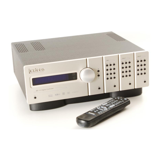
- Page 1 MC-12 Digital Controller User Guide...
- Page 2 IMPORTANT SAFETY INSTRUCTIONS 12. Use only with the cart, stand, tripod, bracket, or mum ambient operating temperature listed in Read these instructions. table specified by the manufacturer, or sold with the the product specification. Keep these instructions. apparatus. When a cart is used, use caution when •...
- Page 3 Telephone: 781-280-0300 Sales Fax: 781-280-0495 Lexicon, Logic 7 and the L7 logo are registered trademarks of Harman International Industries, Inc. U.S. Patent Nos. D454,553; D454,860; 5,796,844; 5,870,480 and other worldwide patents issued and pending. Service Fax: 781-280-0499 © 2005 Harman International Industries, Incorporated. All rights reserved.
-
Page 4: Documentation Conventions
Introduction Lexicon DOCUMENTATION CONVENTIONS This document contains general safety, installation and operation instructions for the MC-12 and MC-12 Balanced Digital Controllers. It is important to read this user guide before attempting to use the product. Pay particular attention to safety instructions. -
Page 5: Table Of Contents
Introduction MC-12 Table of Contents Documentation Conventions............ii Menu Item Selection ............2-11 Important Safety Instructions............v Command Bank Activation ..........2-13 Wichtige Sicherheitshinweise............v Command Matrix ............... 2-14 Instrucciones De Seguridad Importantes........vi About the Zones ..............2-19 Instructions Importantes Relatives À La Sécurité......vi Two-line Status ............... - Page 6 Introduction Lexicon Audio Controls Troubleshooting & Maintenance Audio Controls ................4-2 Troubleshooting ................6-2 Routine Maintenance ..............6-3 Restoring Factory-default Settings..........6-4 Mode Adjust Mode Adjust................5-2 Appendix Listening Mode Activation ............5-2 Preferred Listening Mode Selection Parameters ...... 5-3 Specifications ................A-2 Mode Buttons ............... 5-4 Declaration of Conformity ............A-4...
-
Page 7: Important Safety Instructions
Introduction MC-12 ENGLISH DEUTSCH IMPORTANT SAFETY INSTRUCTIONS WICHTIGE SICHERHEITSHINWEISE Save these instructions for later use. Bewahren Sie diese Anleitungen zur späteren Benutzung auf. Follow all instructions and warnings marked on the unit. Befolgen Sie alle Anleitungen und alle Warnhinweise auf dem Gerät Follow all instructions and warnings marked on the unit. -
Page 8: Instrucciones De Seguridad Importantes
Introduction Lexicon ESPAÑOL FRANÇAIS INSTRUCCIONES DE SEGURIDAD IMPORTANTES INSTRUCTIONS IMPORTANTES RELATIVES À LA SÉCURITÉ Guarde estas instrucciones para futuras referencias. Conservez ces instructions pour pouvoir vous y référer ultérieurement. Siga todas las instrucciones y tenga en cuenta las advertencias que aparecen en la unidad y en las instrucciones de funcionamiento. -
Page 9: Importanti Norme Di Sicurezza
Introduction MC-12 ITALIANO PORTUGUESE IMPORTANTI NORME DI SICUREZZA INSTRUÇÕES IMPORTANTES DE SEGURANÇA Conservare le presenti norme per l’utilizzo futuro. Guarde essas instruções para uso posterior. Seguire sempre tutte le istruzioni e gli avvertimenti segnati sull’unità e nelle istruz- Siga todas as instruções e fique atento aos avisos marcados na unidade e nas ioni operative. -
Page 10: Vigtig Information Om Sikkerhed
Introduction Lexicon DANSK SUOMI VIGTIG INFORMATION OM SIKKERHED TÄRKEITÄ TURVALLISUUSOHJEITA Gem denne vejledning til senere brug. Säilytä nämä ohjeet tulevaa käyttöä varten. Følg alle anvisninger og advarsler på apparatet. Seuraa kaikkia yksikköön merkittyjä ohjeita ja varoituksia. Apparatet skal altid tilsluttes den korrekte spænding. Der henvises til brugsanvis- Käytä... -
Page 11: Viktig Informasjon Om Sikkerhet
Introduction MC-12 NORSK SVENSKA VIKTIG INFORMASJON OM SIKKERHET VIKTIGA SÄKERHETSFÖRESKRIFTER Ta vare på denne veiledningen for senere bruk. Spara dessa föreskrifter för framtida bruk. Følg alle anvisningene og advarslene som er angitt på apparatet. Följ alla anvisningar och varningar som anges på enheten. Apparatet skal alltid anvendes med korrekt spenning. -
Page 12: Unpacking And Inspection
Introduction Lexicon Unpacking and Inspection Contenu de L’emballage et Inspection After unpacking the unit, save all packing materials in case the unit Après avoir ouvert l’emballage, conservez-le pour tout retour. ever needs to be shipped. Thoroughly inspect the modules and Inspectez avec soin les modules et les matériaux d’emballage pour... -
Page 13: Getting Started
Getting Started About The MC-12 ..............1-2 Highlights ....................1-4 Product Registration ..............1-5 Installation Considerations............1-5 Remote Control Battery Installation ..........1-6... -
Page 14: About The Mc-12
More than just an audio and video control center, the MC-12 Logic 7 decoding, bass enhancement, dialog enhancement, auto features the latest version of Lexicon’s critically acclaimed Logic 7 azimuth, 5-speaker enhancement, bass management, high- decoding, which derives 7.1-channel output from stereo, 5.1-, and precision digital crossovers, and tone controls. - Page 15 An unparalleled processor, the MC-12 conveys the best in music Lexicon’s proprietary auto azimuth technology corrects timing and and cinema with awesome power and leading-edge technological level imbalances in stereo sources, ensuring exceptionally accurate sophistication.
-
Page 16: Highlights
Getting Started Lexicon HIGHLIGHTS • 12 channels • 4 component video input connectors with • THX Ultra2 and THX Surround EX full HDTV compatibility decoding • 12 configurable inputs • BNC component video input and output • THX Ultra2 Certification •... -
Page 17: Product Registration
Please register the MC-12 Digital Controller within 15 days of OT place the MC-12 on a windowsill or any location exposed purchase. Register online at www.lexicon.com or complete and to direct sunlight. return the product registration card attached to the back cover of this user guide. -
Page 18: Remote Control Battery Installation
Getting Started Lexicon REMOTE CONTROL BATTERY INSTALLATION The remote control requires two AA batteries. The batteries should be replaced as needed. Alkaline batteries, which last longer without leaking, are recommended. When battery power is low, the remote control enters a low-voltage condition, preventing it from operating the MC-12. -
Page 19: Basic Operation
Basic Operation Front-Panel Overview ..............2-2 Rear-Panel Overview ..............2-6 Remote Control Overview ............2-10 Operation Considerations ............... 2-10 Main Menu .................... 2-11 Menu Navigation ................... 2-11 Menu Item Selection ................2-11 Command Bank Activation ..............2-13 Command Matrix .................. 2-14 About the Zones .............. -
Page 20: Front-Panel Overview
Basic Operation Lexicon FRONT-PANEL OVERVIEW The MC-12 is shown below. The MC-12 Balanced is shown on page 2-4. The front panels are identical, but the MC-12 Balanced has a larger chassis. 1. Standby Button 7. Main Zone Input Selection Buttons 2. - Page 21 Basic Operation MC-12 1 STANDBY BUTTON 4 VOLUME KNOB Use the Standby button to activate or deactivate standby mode. Use the Volume knob to adjust volume level in all zones. The Standby button performs no function when the MC-12 rear Note: panel power switch is powered off.
- Page 22 Basic Operation Lexicon FRONT-PANEL OVERVIEW (continued) The MC-12 Balanced, shown below, has a larger chassis than the MC-12, shown on page 2-2. Otherwise, they are identical. 5 MUTE BUTTON Press the Mute button to mute the MC-12 Main Zone volume;...
- Page 23 Basic Operation MC-12 Mute can be activated automatically or manually. For example, the Zones remain deactivated until a Main or Record Zone input is MC-12 briefly activates mute when changing input sources or selected. listening modes. The amber LED in the Mute button lights whenever mute is activated.
-
Page 24: Rear-Panel Overview
Otherwise both models are identical. The numbers in the rear-panel illustrations correspond with the numbered items. INPUTS MC-12 COMPONENT VIDEO SERIAL NO. MAIN OUTPUTS RECORD OUTPUTS INPUT 1 INPUT 2 INPUT 3 LEXICON, INC. DESIGNED AND ASSEMBLED IN U.S.A. 1 (OSD) INPUT 4 OUTPUT VIDEO VIDEO FRONT CENTER... - Page 25 Basic Operation MC-12 Caution! When a 5.1-channel analog audio source is present in the Main Zone, input signals are sent to the Main Zone audio output connectors as Never make or break connections to the MC-12 unless the indicated in the table below. When a 5.1-channel analog source is MC-12 and all associated components are powered off.
- Page 26 The MC-12 is shown on page 2-4. The MC-12 Balanced, shown below, includes balanced audio connectors for the Main Zone and Zone 2. Otherwise both models are identical. INPUTS MC-12 COMPONENT VIDEO SERIAL NO. MAIN OUTPUTS RECORD OUTPUTS INPUT 1 INPUT 2 INPUT 3 LEXICON, INC. DESIGNED AND ASSEMBLED IN U.S.A. 1 (OSD) INPUT 4 OUTPUT VIDEO VIDEO ZONE 2 FRONT CENTER...
- Page 27 Basic Operation MC-12 7 RECORD ZONE AUDIO OUTPUT CONNECTORS 10 MAIN VIDEO OUTPUT CONNECTORS Provide analog and digital audio output in the Record Zone. Two Provide video output in the Main Zone. Two composite video stereo connectors labeled Audio L/R are available for analog audio connectors, two S-video connectors, and one component video output.
-
Page 28: Remote Control Overview
Basic Operation Lexicon REAR-PANEL OVERVIEW (continued) 13 TRIGGER OUTPUT CONNECTORS REMOTE CONTROL OVERVIEW Provide 12V DC output to control connected components. Three The MC-12 remote control provides full operation of the MC-12, trigger output connectors are available on a removable terminal block. -
Page 29: Main Menu
Basic Operation MC-12 MAIN MENU MENU NAVIGATION The MAIN MENU represents the beginning of Use the remote control Menu and arrow buttons to navigate the MAIN MENU the menu structure. Use the MAIN MENU to extensive menu structure shown in the Appendix. The table below MODE ADJUST open the three main menu branches: MODE AUDIO CONTROLS... - Page 30 Basic Operation Lexicon MENU OPTIONS displayed beneath the parameter name in the on-screen and front-panel displays. Selecting a menu option opens another menu within the menu 2. When the desired setting appears beneath the parameter structure. For example, selecting SETUP from the MAIN MENU opens...
-
Page 31: Command Bank Activation
Basic Operation MC-12 COMMAND BANK ACTIVATION Remote control buttons perform different commands depending on The MAIN MENU SETUP DISPLAYS ON-SCREEN DISPLAY whether the Main Zone, Zone 2, Record Zone, or Shift command menu REMOTE STATE parameter controls the remote control bank is activated. -
Page 32: Command Matrix
Basic Operation Lexicon COMMAND MATRIX The command matrix describes the commands remote control buttons perform when each command bank is active. Button Main Zone Zone 2 Record Zone Shift Activates and deactivates standby mode when the MC-12 rear panel power switch is in the on position. - Page 33 Basic Operation MC-12 Button Main Zone Zone 2 Record Zone Shift Selects the SAT input for Selects the SAT input for Selects the SAT input for Sets the AUDIO the Main Zone. Zone 2. the Record Zone. CONTROLS menu LOUDNESS parameter to OFF.
- Page 34 Basic Operation Lexicon Button Main Zone Zone 2 Record Zone Shift Toggles the FRONT Sets Zone 2 volume Sets Record Zone Sets Main Zone volume PANEL DISPLAY menu level to -15dB volume level to -15dB level to -15dB. STATUS parameter between ALWAYS OFF and the current setting.
- Page 35 Basic Operation MC-12 Button Main Zone Zone 1 Record Zone Shift Displays the Main Zone Displays the Zone 2 Displays the Record Opens and closes the status menu for the line status for 2 line status for 2 Zone two line status current input source.
- Page 36 Basic Operation Lexicon Button Main Zone Zone 1 Record Zone Shift Selects the THX mode Reserved for possible Reserved for possible Activates the 5.1 THX family for the current future expansion. future expansion. ULTRA2, 5.1 THX SurEX, input source. or 5.1 THX listening...
-
Page 37: About The Zones
Basic Operation MC-12 ABOUT THE ZONES The MC-12 features three zones of operation: the Main Zone, Zone 3. When the MAIN MENU SETUP INPUTS INPUT SETUP menu 2, and the Record Zone. The Main Zone controls audio and video ZONE2 IN or RECORD IN parameter is set to ANLG, the Zone 2 or sources in the primary listening space. -
Page 38: Status Menus
Basic Operation Lexicon RECORD ZONE TWO-LINE STATUS To open and navigate the STATUS menu for the current input source: Opens on the on-screen and front panel DVD1 1. Press and release the remote control SHIFT button. displays whenever the MC-12 detects a... -
Page 39: Status Menu Descriptions
Basic Operation MC-12 STATUS MENU DESCRIPTIONS D STATUS The table beneath each description lists the default and possible Provides information about Dolby Digital input sources. Features L, settings for each parameter. C, R, SL, SR and SUB level meters. 2CH STATUS Parameter Possible Settings Provides information about 2-channel input sources. - Page 40 Basic Operation Lexicon STATUS 5.1 ANALOG STATUS Provides information about DTS-ES input sources. Includes L, C, R, Provides information about 5.1-channel analog sources. Includes L, SL, SR, SB and LFE level meters. C, R, SL, and LFE level meters. Parameter...
- Page 41 Basic Operation MC-12 5.1a BYPASS STATUS 2CH BYPASS STATUS Provides information about 5.1-channel analog input sources when Provides information about 2-channel analog input sources when the MAIN ADV menu ANALOG BYPASS parameter is set to ON. the MAIN ADV menu ANALOG BYPASS parameter is set to ON. Parameter Possible Settings Parameter...
- Page 42 Basic Operation Lexicon DIGITAL STATUS LIVE! STATUS Provides information about digital input sources for which a sample Provides information about LIVE! input sources. rate is detected, but no audio is present in the input signal. Parameter Possible Settings Parameter Possible Settings...
-
Page 43: Status Menu Parameter Descriptions
Basic Operation MC-12 STATUS MENU PARAMETER DESCRIPTIONS Possible settings for Dolby Digital input sources include 3/2.1, 3/2, 3/1, 2/2, 2/1, 2/0 and 1/0. Current settings for DTS-ES input sources include 3/3.1 and 3/2.1. 2.0 ENCODING MATRIX, NONE DIALOG OFFSET -27 to +4dB Indicates whether or not a matrix-encoded source is detected. -
Page 44: Status Menu Level Meters
Basic Operation Lexicon INPUT STATUS MENU LEVEL METERS Indicates the selected input (for example, DVD1). Most STATUS menus contain level meters that indicate fluctuating input levels in the front left (L), center (C), front right (R), surround left INPUT TYPE... -
Page 45: Setup
Setup Setup ..................3-2 Input Setup ................3-4 Changing Input Names ................3-5 Assigning Audio & Video Input Connectors ..........3-7 Selecting Preferred Listening Modes ............3-12 Configuring Advanced Input Settings ............. 3-15 INPUT SELECT Parameter Settings ............3-17 ZONE2 & RECORD IN Parameter Settings ..........3-19 Speaker Setup ................3-22 Setting Crossover Points ................. -
Page 46: Setup
Setup Lexicon SETUP Selecting SETUP from the MAIN MENU opens the SETUP menu. REAR PANEL CONFIG SETUP REAR PANEL CONFIG MAIN MENU SETUP Opens the REAR PANEL CONFIG menu, to configure the analog audio input MODE ADJUST INPUTS connectors as eight stereo connectors or as five stereo and one 5.1-channel... - Page 47 Setup MC-12 LOCK OPTIONS LIVE! CALIBRATION SETUP LOCK OPTIONS SETUP LIVE! CALIBRATION Opens the LOCK OPTIONS menu, to protect MODE ADJUST, Opens the LIVE! CALIBRATION menu, to perform the necessary AUDIO CONTROLS and SETUP menu branch settings from calibration before using the LIVE! modes. See “LIVE! Calibration” on accidental changes.
-
Page 48: Input Setup
Setup Lexicon INPUT SETUP SETUP INPUTS (INPUT) INPUT SETUP Selecting the SETUP menu INPUTS option prompts the selection of a desired input (e.g., DVD1). Selecting an input opens the corresponding INPUT SETUP menu, which changes input names, assigns audio and video input connectors, selects preferred listening modes, and configures advanced Main Zone, Zone 2, and Record Zone settings. -
Page 49: Changing Input Names
Setup MC-12 CHANGING INPUT NAMES Selecting the INPUT SETUP menu NAME parameter opens the INPUT NAME menu, to customize or restore the factory-default name of the selected input. Factory-default input names correspond to front-panel and remote control input selection button labels. DVD1 INPUT SETUP SETUP INPUT SETUP... - Page 50 Setup Lexicon CHANGING INPUT NAMES (continued) Note: The custom input name appears in the on-screen and front-panel displays. Both the custom and factory-default input names appear Pressing the arrow button closes the menu and returns to the INPUT in the INPUT SETUP menu. The custom input name appears against NAME menu.
-
Page 51: Assigning Audio & Video Input Connectors
Setup MC-12 ASSIGNING AUDIO & VIDEO INPUT CONNECTORS The MC-12 has 12 inputs, each of which can be assigned to any (depending on compatibility) of its 13 digital audio, 8 analog audio, 5 composite video, 8 S-video, or 4 component video input connectors. MAIN MENU SETUP INPUT SETUP... - Page 52 Setup Lexicon ASSIGNING AUDIO & VIDEO INPUT CONNECTORS (continued) ANALOG IN ANALOG-1 TO 8, 5.1 ANLG (6-8), LIVE!, NONE SETUP INPUTS DVD1 ANALOG IN Opens the ANALOG IN menu, to assign an analog audio input When no digital audio input connector is assigned, the MC-12 connector for the selected input.
- Page 53 Setup MC-12 ANLG IN LVL AUTO, -18 to +12 dB Note: SETUP INPUTS DVD1 ANGL IN LVL Adjustments made on the ANLG IN LVL menu are applied to the stereo Opens the ANLG IN LVL menu, to adjust the 2-channel (and analog audio input connector assigned for the selected input.
- Page 54 Setup Lexicon ASSIGNING AUDIO & VIDEO INPUT CONNECTORS (continued) MANUAL When the AUTO parameter is OFF, the AUTO GAIN parameter -18 to +12 dB indicates the amount of input level adjustment as set by the SETUP INPUTS DVD1 ANGL IN LVL MANUAL MANUAL parameter.
- Page 55 Setup MC-12 VIDEO IN COMPONENT IN COMPOSITE-1 TO 5, S-VIDEO-1 TO 8, NONE COMPONENT 1 to 4 SETUP INPUTS DVD1 VIDEO IN DVD1 COMPONENT IN SETUP INPUTS Opens the VIDEO IN menu, to assign a composite or S-video input Opens the COMPONENT IN menu, to assign a component video connector for the selected input.
-
Page 56: Selecting Preferred Listening Modes
Setup Lexicon SELECTING PREFERRED LISTENING MODES The MC-12 allows the selection of five preferred listening modes for When a preferred listening mode is selected, it is activated each Main Zone input: one listening mode each for 2-channel, whenever a new input is selected or an appropriate input source is Dolby Digital, DTS(-ES), 5.1-channel analog, and MIC (LIVE!) - Page 57 Setup MC-12 2-CH DVD1 DVD1 SETUP INPUTS SETUP INPUTS 2-CH Opens the 2-CH MODE menu, which selects a preferred listening Opens the Dolby DIGITAL MODE menu, to select a preferred mode for 2-channel input sources. The MC-12 activates the listening mode for Dolby Digital input sources. The MC-12 preferred listening mode whenever a new input is selected or a new automatically activates the preferred listening mode whenever a 2-channel source is present.
- Page 58 Setup Lexicon SELECTING PREFERRED LISTENING MODES (continued) 5.1a DVD1 SETUP INPUTS 5.1a DVD1 SETUP INPUTS Opens the 5.1a MODE menu, which selects a preferred listening Opens the DTS(-ES) MODE menu, which selects a preferred mode for 5.1-channel analog input sources. The MC-12 automati- listening mode for DTS(-ES) input sources.
-
Page 59: Configuring Advanced Input Settings
Setup MC-12 CONFIGURING ADVANCED INPUT SETTINGS SETUP MAIN MENU INPUT SETUP DVD1 INPUT SETUP DVD1 MAIN ADV DIGITAL ANALOG INPUTS MODE ADJUST DVD1 NAME DVD1 INPUT SELECT DIGITAL AUTO SPEAKERS DVD2 AUDIO CONTROLS DIGITAL IN COAX-1 ANALOG BYPASS REAR PANEL CONFIG SETUP ANALOG IN NONE... - Page 60 Setup Lexicon CONFIGURING ADVANCED ZONE SETTINGS (continued) INPUT SELECT • When LIVE! is the selected analog input, the MAIN DIGITAL, ANALOG, AUTO ADVANCED INPUT SELECT parameter is forced to ANALOG SETUP INPUTS DVD1 MAIN ADVANCED INPUT SELECT and ANALOG BYPASS is disabled.
-
Page 61: Input Select Parameter Settings
Setup MC-12 INPUT SELECT PARAMETER SETTINGS DIGITAL ANALOG AUTO The MC-12 sends the digital audio from the The MC-12 sends the analog audio from the The MC-12 toggles between sending digital or assigned input to the Main Zone audio assigned input to the Main Zone audio output analog audio input to the Main Zone audio output output connectors. - Page 62 Setup Lexicon CONFIGURING ADVANCED ZONE SETTINGS (continued) S-VIDEO OSD 4:3 COMPONENT OSD ON, OFF ON, OFF DVD1 S-VIDEO OSD 4:3 SETUP INPUTS MAIN ADVANCED SETUP INPUTS DVD1 MAIN ADVANCED COMPONENT OSD Controls the on-screen display aspect ratio when the display device Controls the appearance of the on-screen display when the display is connected to a Main Zone S-Video output connector.
-
Page 63: Zone2 & Record In Parameter Settings
Setup MC-12 ZONE2 & RECORD IN PARAMETER SETTINGS DIGITAL ANLG (Analog) DMIX (Downmix) The MC-12 passes digital audio The MC-12 passes analog audio from The MC-12 passes a downmixed version of Main Zone audio to the Zone 2 or Record Zone audio output connectors. Zones cannot be from the the assigned input to the the assigned input to the Zone 2 the Zone 2 or Record Zone audio... - Page 64 Setup Lexicon CONFIGURING ADVANCED ZONE SETTINGS (continued) RECORD ADVANCED ANLG IN LVL -18 to +12dB SETUP INPUTS DVD1 RECORD ADVANCED SETUP INPUTS DVD1 RECORD ADVANCED ANLG IN LVL Opens the RECORD ADV menu, which configures advanced Record Allows adjustment of analog audio input levels for input signals sent to the Record Zone digital audio output connectors.
- Page 65 Setup MC-12 DIG OUT RATE RECORD INPUT, 44.1kHz, 48kHz, 88.2kHz, 96kHz BLOCKED, ENABLED SETUP INPUTS DVD1 RECORD ADVANCED DIG OUT RATE SETUP INPUTS DVD1 RECORD ADVANCED RECORD Controls the sample rate of digital and analog input signals sent to Prevents recording device feedback loops. When BLOCKED is the Record Zone digital audio output connectors.
-
Page 66: Speaker Setup
Setup Lexicon SPEAKER SETUP Note: SETUP SPEAKERS The MC-12 Balanced also includes 10 balanced Main Zone audio output connectors labeled Front L/R, Center, LFE, Subwoofer L/R, Side Selecting the SETUP menu SPEAKERS option opens the SPEAKER L/R, and Rear L/R. Two additional audio output connectors labeled Aux SETUP menu, which configures the Main Zone audio output L/R are provided for future expansion. - Page 67 Setup MC-12 MAIN MENU SETUP SPEAKER SETUP CUSTOM SETUP CROSSOVER SETUP CUSTOM SETUP SETUP FRONT L/R 80 Hz INPUTS SET CROSSOVERS CUSTOM SETUP 40 Hz MODE ADJUST INPUTS CENTER 80 Hz SPEAKERS CHECK MICROPHONES THX SETUP 60 Hz AUDIO CONTROLS SPEAKERS SIDE L/R 80 Hz...
- Page 68 Setup Lexicon SETTING CROSSOVER POINTS (continued) High-pass Filter Low-pass Filter High-pass filters attenuate low frequencies at 24dB per octave. The curves in the graph Low-pass filters attenuate high frequencies at 24dB per octave. The curves in the graph above indicate the frequency response of each crossover setting. From left to right, the above indicate the frequency response of each crossover setting.
- Page 69 Setup MC-12 CUSTOM SETUP CROSSOVER SETUP SETUP SPEAKER SETUP CUSTOM SETUP CROSSOVER SETUP THX SPEAKER SETUP THX SETUP CUSTOM SETUP 40 Hz INPUTS CUSTOM SETUP 40 Hz !CAUTION! FRONT L/R THX 80Hz SET CROSSOVERS THX SETUP 60 Hz SPEAKERS THX SETUP 60 Hz CENTER THX 80Hz...
- Page 70 Setup Lexicon SPEAKER SETUP PARAMETERS SETUP SPEAKERS SET CROSSOVERS CUSTOM SETUP SETUP SPEAKERS SET CROSSOVERS THX SETUP The table below indicates the speaker setup parameters for config- Speaker setup parameters perform the same function regardless of uring the Main Zone audio output connectors for the desired the selected speaker setup.
- Page 71 Setup MC-12 CUSTOM SETUP SETUP CUSTOM SETUP CROSSOVER SETUP MAIN MENU SPEAKER SETUP FRONT L/R 40Hz INPUTS CUSTOM SETUP 40 Hz SET CROSSOVERS MODE ADJUST CENTER 60Hz SPEAKERS THX SETUP 60 Hz CHECK MICROPHONES AUDIO CONTROLS SIDE L/R 60Hz REAR PANEL CONFIG 60 Hz AUTOMATIC SETUP...
- Page 72 Setup Lexicon SETTING CROSSOVER POINTS SIDE L/R FULL, FULL + SUB, 30Hz to 120Hz, THX 80Hz, NONE (continued) SETUP SPEAKERS SET CROSSOVERS THX SETUP SETUP SPEAKERS SET CROSSOVERS CUSTOM SETUP SIDE L/R When a THX speaker setup is selected, a THX 80Hz crossover point...
- Page 73 Setup MC-12 SETUP MAIN MENU SPEAKER SETUP CUSTOM SETUP CROSSOVER SETUP THX SPEAKER SETUP THX SETUP FRONT L/R THX 80Hz INPUTS SET CROSSOVERS CUSTOM SETUP 40 Hz !CAUTION! MODE ADJUST CENTER THX 80Hz SPEAKERS CHECK MICROPHONES THX SETUP 60 Hz AUDIO CONTROLS PRESSING THE SIDE L/R...
- Page 74 Setup Lexicon SETTING CROSSOVER POINTS (continued) SUB L/R SUB XOVER MONO, STEREO, NONE FULL, 30 to 120Hz, THX 80Hz, NONE SETUP SPEAKERS SET CROSSOVERS CUSTOM SETUP SUB XOVER SETUP SPEAKERS SET CROSSOVERS CUSTOM SETUP SUB L/R Assigns a crossover point for the Main Zone audio output...
- Page 75 Setup MC-12 THX ULTRA2 SUB ON, OFF SETUP SPEAKERS SET CROSSOVERS THX SETUP SETUP SPEAKERS SET CROSSOVERS CUSTOM SETUP ULTRA2 SUB When a THX speaker setup is selected, the LFE information is redirected to SETUP SPEAKERS SET CROSSOVERS THX SETUP ULTRA2 SUB the SUBWOOFER L/R output connectors, and the LFE parameter cannot be adjusted.
- Page 76 Setup Lexicon BGC (BOUNDARY GAIN COMPENSATION) To maximize the effectiveness of ASA processing, configure a ON, OFF 7.1-channel speaker setup so the rear speakers are placed close SETUP SPEAKERS SET CROSSOVERS CUSTOM SETUP together facing the center of the listening space.
-
Page 77: Calibrating Speaker Distances & Output Levels
Setup MC-12 CALIBRATING SPEAKER DISTANCES & OUTPUT LEVELS The MC-12 offers both automatic and manual calibration of speaker distances and output levels. Calibration helps to ensure accurate output signal arrival time and level at the primary listening position. However, it is not a substitute for proper speaker placement. Before calibrating speaker distances and output levels: SPEAKER CALIBRATION PARAMETERS The table on the next page indicates the speaker calibration param-... - Page 78 Setup Lexicon UNITS FEET, METERS SETUP SPEAKERS MANUAL SPEAKER DISTANCES UNITS Determines the unit of measurement in which speaker distances are calculated on ALL speaker distance menus. When FEET is selected, the MC-12 calculates speaker distances in feet. When METERS is selected, the MC-12 calculates speaker distances in meters. When the UNITS parameter setting is adjusted, the MC-12 automatically adjusts speaker distances to the closest available value in the selected unit of measurement.
-
Page 79: Automatic Calibration
Setup MC-12 AUTOMATIC CALIBRATION The MC-12 offers automatic calibration of speaker distances, output levels, or both. The table below indicates available automatic calibration options. A successful microphone check is required before automatic calibration can be performed. Automatic Options Details MICROPHONE CHECK •... - Page 80 OR standby mode is activated with the front panel or remote control standby button. 1. Make sure the MC-12 is powered off OR in standby mode. 2. Connect the microphones included in the Lexicon Microphone Note the following: Kit to the microphone input connectors on the MC-12 rear panel as shown above.
- Page 81 Setup MC-12 POSITIONING THE MICROPHONES FOR THE MICROPHONE CHECK Refer to the microphone placement examples that begin below to position the microphones for the microphone check. PROPER microphone positioning for the microphone check During the microphone check, position the microphones: 3 As close together as possible 3 Relatively centered between and equidistant from the front left and right speakers...
- Page 82 Setup Lexicon IMPROPER microphone positioning for the microphone check During the microphone check, do not: 7 Separate the microphones 7 Scatter the microphones throughout the listening space 7 Obstruct the line-of-sight path between the micro- phones and the speakers Rear...
- Page 83 Setup MC-12 CHECKING THE MICROPHONES SETUP SPEAKER SETUP CUSTOM SETUP CHECK MICROPHONES MAIN MENU INPUTS SET CROSSOVERS MODE ADJUST GROUP MICROPHONES 40 Hz SPEAKERS CHECK MICROPHONES INTO A BUNDLE IN THE 60 Hz AUDIO CONTROLS AUTOMATIC SETUP REAR PANEL CONFIG MIDDLE OF THE ROOM 60 Hz MANUAL...
- Page 84 Setup Lexicon CHECKING THE MICROPHONES (continued) level. If the signal becomes too loud, press the arrow button 4. Press the arrow buttons to highlight the desired to cancel the microphone check. microphone parameter. The MC-12 refers to the microphones according to the input connector to which the microphone is The MC-12 uses the calibration noise signal to eliminate micro- connected.
- Page 85 MC-12 and that microphone cable plugs are fully inserted for a solid connection. phone during the silence check. NOT DETECTED • The microphone might be damaged. Contact an authorized Lexicon dealer for assistance. The MC-12 detected the microphone • Examine microphone input connections to ensure that the microphones are properly con- (MICROPHONE) nected to the MC-12 and that microphone cable plugs are fully inserted for a solid connection.
- Page 86 Setup Lexicon POSITIONING THE MICROPHONES FOR AUTOMATIC CALIBRATION (continued) PROPER microphone placement to achieve the best results for a single listening position When calibrating for a single listening position, place the microphones: 3 As close together as possible in a single listening position (the primary listening position) 3 At the approximate spot where the listener’s...
- Page 87 Setup MC-12 PROPER microphone placement to achieve the best results for multiple listening positions in a single row When calibrating for multiple listening positions in a single row, position the microphones: 3 At the approximate spot where the listener’s head will be during listening 3 In a clear line-of-sight path with the speakers Rear Left...
- Page 88 Setup Lexicon POSITIONING THE MICROPHONES FOR AUTOMATIC CALIBRATION (continued) PROPER microphone placement to achieve the best results for multiple listening positions in multiple rows When calibrating for multiple listening positions in multiple rows, position the microphones: 3 At the approximate spot where the listener’s...
- Page 89 Setup MC-12 IMPROPER microphone positioning for automatic calibration During the automatic calibration, do not: 7 Arrange the microphones along the perimeter of the listening positions or space 7 Position the microphones in spots where the listeners’ heads will not be during listening Rear Left 7 Obstruct the line-of-sight path between the...
- Page 90 Setup Lexicon POSITIONING THE MICROPHONES FOR AUTOMATIC CALIBRATION (continued) IMPROPER microphone positioning for automatic calibration During the automatic calibration, do not: 7 Arrange the microphones along the perimeter of the listening positions or space 7 Position the microphones at spots where the listeners’...
- Page 91 Setup MC-12 PERFORMING AUTOMATIC CALIBRATION MAIN MENU SETUP SPEAKER SETUP CUSTOM SETUP AUTO SPEAKER SETUP CUSTOM SETUP AUTO SPEAKER SETUP AUTO SPEAKER SETUP INPUTS SET CROSSOVERS MODE ADJUST DISTANCES & LEVELS 40 Hz !CAUTION! 40 Hz TEST WILL BEGIN IN SPEAKERS CHECK MICROPHONES AUDIO CONTROLS...
- Page 92 Setup Lexicon PERFORMING AUTOMATIC CALIBRATION (continued) SETTING DISTANCES SETTING DISTANCES SETTING LEVELS SETTING LEVELS CUSTOM SETUP CUSTOM SETUP CUSTOM SETUP CUSTOM SETUP FRONT LEFT 0.0ft FRONT LEFT 12.0ft FRONT LEFT 0.0dB FRONT LEFT -2.0dB CENTER 0.0ft CENTER 10.5ft CENTER 0.0dB...
- Page 93 Setup MC-12 STEP DISTANCES & LEVELS LEVELS DISTANCES AUTO LEVELS AUTO DISTANCES AUTO SPEAKER SETUP FRONT LEFT FRONT LEFT DISTANCES FRONT LEFT -2.0dB FRONT LEFT 12.0ft LEVELS ERROR CENTER ERROR CENTER 10.5ft Refer to the table on page Refer to the table on page FRONT RIGHT -2.0dB FRONT RIGHT...
- Page 94 Setup Lexicon PERFORMING AUTOMATIC CALIBRATION (continued) STEP DISTANCES DISTANCES & LEVELS LEVELS SET DISTANCES AUTO DISTANCES AUTO SPEAKER SETUP AUTO DISTANCES* SET LEVELS AUTO LEVELS AUTO DISTANCES FRONT LEFT 12.0ft DISTANCES FRONT LEFT 12.0ft AUTO LEVELS FRONT LEFT -2.0dB ORIGINAL DISTANCES CENTER 10.5ft...
- Page 95 Setup MC-12 Message Description Troubleshooting The MC-12 successfully calibrated the value • (SPEAKER) for the selected speaker without error. The selected speaker is not present in the • Set the corresponding CUSTOM or THX SETUP menu parameter to include the selected (SPEAKER) speaker in the speaker setup.
-
Page 96: Manual Calibration
Setup Lexicon MANUAL CALIBRATION SETUP SPEAKERS MANUAL Selecting the SPEAKER SETUP menu MANUAL option displays the MANUAL SPEAKER SETUP menu, to manually calibrate speaker distances and output levels. The table below indicates available manual calibration options. MAIN MENU SETUP SPEAKER SETUP... - Page 97 Setup MC-12 PERFORMING MANUAL SPEAKER DISTANCE CALIBRATION SETUP SPEAKERS MANUAL SPEAKER DISTANCES Selecting the MANUAL SPEAKER SETUP menu SPEAKER DISTANCES option displays the SPEAKER DISTANCES menu, to manually calibrate speaker distances. SETUP MAIN MENU SPEAKER SETUP MANUAL SPEAKER SETUP CUSTOM SETUP SPEAKER DISTANCES INPUTS SET CROSSOVERS...
- Page 98 Setup Lexicon PERFORMING MANUAL OUTPUT LEVEL CALIBRATION SETUP SPEAKERS MANUAL LEVELS CALIBRATION Selecting the MANUAL SPEAKER SETUP menu LEVELS CALIBRATION option displays the LEVELS CALIBRATION menu to manually calibrate output levels. Note the following: • You should use a Sound Pressure Level (SPL) meter to manually •...
- Page 99 Setup MC-12 INTERNAL NOISE TEST INTERNAL NOISE TEST SETUP SPEAKERS MANUAL LEVELS CALIBRATION To manually calibrate output levels during the internal noise test: Opens the INTERNAL NOISE message shown on the previous page, which indicates that the internal noise test generates loud 1.
- Page 100 Setup Lexicon EXTERNAL NOISE TEST EXTERNAL NOISE TEST SETUP SPEAKERS MANUAL LEVELS CALIBRATION Selecting the LEVELS CALIBRATION menu EXTERNAL NOISE TEST Note: option opens the SPEAKER LEVEL ADJUST menu shown on page When the external noise test begins, the MC-12 automatically sets 3-54, which manually calibrates output levels.
- Page 101 Setup MC-12 SETTING BASS PEAK LIMITERS BASS PEAK LIMITERS SETUP SPEAKERS MANUAL LEVELS CALIBRATION The BASS PEAK LIMITERS option displays the BASS PEAK LIMITERS menu to set amplitude limits on low frequency signals sent to the Main Zone audio output Subwoofer L/R and LFE connectors. This menu also sets amplitude limits on low frequency signals redirected to other Main Zone audio output connectors.
- Page 102 Setup Lexicon CAL NOISE L/R LIMIT ADJ ON, OFF 75 to 120dB SETUP SPEAKERS MANUAL LEVELS CALIBRATION BASS PEAK LIMITERS SETUP SPEAKERS MANUAL LEVELS CALIBRATION BASS PEAK LIMITERS L/R LIMITER ADJ CAL NOISE Determines whether bass peak limiters are set with an internal or Specifies the output level restriction applied to the Subwoofer L/R external calibration source.
-
Page 103: Rear-Panel Configuration
Setup MC-12 LFE LIMITER ADJ To set the LFE LIMIT ADJ parameter: 75 to 120dB SETUP SPEAKERS MANUAL LEVELS CALIBRATION BASS PEAK LIMITERS 1. Select the LFE LIMIT ADJ parameter. LFE LIMITER ADJ The parameter initally sets to 75dB. Specifies the output level restriction the MC-12 applies to the LFE 2. - Page 104 Setup Lexicon 5 STEREO & 5.1 ANLG SETUP REAR PANEL CONFIG 5 STEREO & 5.1 ANLG Select the 5 STEREO & 5.1 ANLG option to configure the analog audio • The 5.1-channel input is sent to the Main Zone audio output connectors as indicated in the table below.
-
Page 105: Display Setup
Setup MC-12 DISPLAY SETUP SETUP DISPLAYS The DISPLAYS option displays the DISPLAY SETUP menu, to customize the on-screen and front-panel displays, restore audio/video synchroni- zation, and create and activate a custom unit name. SETUP MAIN MENU DISPLAY SETUP OFF, 1 to 60ms INPUTS ON-SCREEN DISPLAY MODE ADJUST... - Page 106 Setup Lexicon DISPLAY SETUP (continued) MAIN MENU SETUP DISPLAY SETUP EDIT CUSTOM NAME MC-12 MODE ADJUST INPUTS ON-SCREEN DISPLAY AUDIO CONTROLS SPEAKERS FRONT PANEL DISPLAY SETUP REAR PANEL CONFIG A/V SYNC DELAY BUTTONS TO EDIT DISPLAYS CUSTOM NAME UP TO 20 CHARACTERS...
-
Page 107: On-Screen Display
Setup MC-12 ON-SCREEN DISPLAY SETUP DISPLAYS ON-SCREEN DISPLAY The ON-SCREEN DISPLAY option opens the ON-SCREEN DISPLAY menu, to customize the on-screen display. SETUP MAIN MENU DISPLAY SETUP ON-SCREEN DISPLAY ALWAYS ON 2 SECONDS INPUTS MODE ADJUST ON-SCREEN DISPLAY STATUS 2 SECONDS ALWAYS OFF SPEAKERS AUDIO CONTROLS... - Page 108 Setup Lexicon the two-line status appears centered on the display device screen. Note: When BOTTOM is selected, the two-line status appears near the When the BACKGROUND parameter is set to OFF, the on-screen bottom of the display device screen. display automatically deactivates when the display device is connected to the Main Zone component video output connector.
-
Page 109: Front-Panel Display
Setup MC-12 FRONT-PANEL DISPLAY SETUP DISPLAYS FRONT PANEL DISPLAY Opens the FRONT PANEL DISPLAY menu, to customize the front panel display. MAIN MENU SETUP DISPLAY SETUP FRONT PANEL DISPLAY ALWAYS ON 2 SECONDS MODE ADJUST INPUTS ON-SCREEN DISPLAY STATUS ALWAYS ON ALWAYS OFF AUDIO CONTROLS SPEAKERS... -
Page 110: Volume-Control Setup
Setup Lexicon VOLUME-CONTROL SETUP SETUP VOLUME CONTROLS Opens the VOLUME CONTROL SETUP menu, to configure the Main level to the selected value when the Main Zone is activated. When Zone, Zone 2, and Record Zone volume levels. LAST LVL is selected, the MC-12 sets Main Zone volume level to the last volume level that was selected in the Main Zone during the previous operating session. - Page 111 Setup MC-12 volume level to the last volume level that was selected in the Record Zone during the previous operating session. MAX VOLUME -80 to +12dB SETUP VOLUME CONTROLS MAX VOLUME Selects the maximum volume level for the Main Zone. When a value is selected, the MC-12 automatically sets Main Zone volume level to the selected value.
-
Page 112: Trigger Setup
Setup Lexicon TRIGGER SETUP TRIGGER SETUP TRIGGER SETUP REMOTE ONLY 5.1 MONO SURR SETUP TRIGGERS DVD1 5.1 MONO DVD2 FILM MUSIC MUSIC SETUP TRIGGER SETUP MAIN MENU INPUTS TRIGGER 1 REMOTE 2-CHAN MODE ADJUST 5.1a FILM SPEAKERS TRIGGER 2 REMOTE... - Page 113 Setup MC-12 TRIGGER SETUP continued REMOTE ONLY Note the following: ON, OFF SETUP TRIGGER 2 REMOTE ONLY TRIGGERS TRIGGER 1 • Connectors can be associated with individual Main Zone inputs and listening modes, as well as the Zone 2 and Record Zone Configures the selected trigger output connector for remote inputs.
-
Page 114: Lock Options
Setup Lexicon LOCK OPTIONS SETUP LOCK OPTIONS Displays the LOCK OPTIONS menu, which protects MODE ADJUST, AUDIO CNTRL LOCKED, UNLOCKED AUDIO CONTROLS, and SETUP menu branch parameter settings SETUP LOCK OPTIONS AUDIO CNTRL from accidental changes. Protects AUDIO CONTROLS menu branch settings from accidental LOCK OPTIONS changes. -
Page 115: Live! Calibration
LIVE! requires 2 microphones, available in a kit from your authorized Lexicon dealer. (If you already own the Lexicon 4-microphone kit, 2. Connect the Lexicon microphones to the microphone input 1 and there is no need to purchase the 2-microphone kit) These microphones 2 connectors on the MC-12 rear panel shown above. - Page 116 Setup Lexicon POSITIONING THE MICROPHONES FOR LIVE! Refer to the microphone placement examples below to position the microphones for LIVE! PROPER microphone positioning for LIVE! Position the microphones: 3 On or near opposite side walls 3 Approximately halfway between the front and...
- Page 117 Setup MC-12 IMPROPER microphone positioning for LIVE! When positioning the microphones, do not: 7 Place the microphones on the front or rear walls 7 Place the microphones near the floor or ceiling Rear Left 7 Obstruct the microphones with furniture or other fixtures Side Left...
- Page 118 Setup Lexicon PERFORMING LIVE! CALIBRATION SETUP CUSTOM SETUP LIVE! CALIRATION LIVE! CALIBRATION LIVE! CALIBRATION MAIN MENU INPUTS MODE ADJUST !CAUTION! 40 Hz TEST WILL BEGIN IN IN PROGRESS LIVE! CALIBRATION SPEAKERS AUDIO CONTROLS HIGH AUDIO LEVELS 60 Hz SETUP REAR PANEL CONFIG...
-
Page 119: Audio Controls
Audio Controls Audio Controls ................4-2... - Page 120 Audio Controls Lexicon AUDIO CONTROLS Selecting the MAIN MENU AUDIO CONTROLS option opens the AUDIO CONTROLS menu, to customize the Main Zone, Zone 2, and Record Zone audio output connectors. MAIN MENU AUDIO CONTROLS BASS +0.0dB MODE ADJUST TREBLE +0.0dB...
- Page 121 Audio Controls MC-12 BASS -6.0dB to +6.0dB BASS AUDIO CONTROLS BASS Controls the amount of low-frequency boost or cut applied to the Main Zone audio output connectors labeled Front L/R, Center, LFE, and Subwoofer L/R. The graph to the right indicates the frequency response of all BASS parameter settings.
- Page 122 Audio Controls Lexicon TREBLE -6.0dB to +6.0dB TREBLE AUDIO CONTROLS TREBLE Controls the amount of boost or cut applied to the Main Zone audio output connectors labeled Front L/R and Center. The graph shown at the right indicates the frequency response of all TREBLE parameter settings.
- Page 123 Audio Controls MC-12 TILT EQ -3.0 to +3.0 TILT EQ AUDIO CONTROLS TILT EQ Controls the amount of tilt equalization applied to the Main Zone audio output connectors labeled Front L/R, Center, LFE, and Subwoofer L/R. This parameter setting affects the entire frequency spectrum with a hinge point at 1kHz.
- Page 124 Audio Controls Lexicon LOUDNESS ON, OFF LOUDNESS AUDIO CONTROLS LOUDNESS Controls the amount of low-frequency boost that is automatically applied to the Main Zone audio output connectors labeled Front L/R, Center, LFE, and Subwoofer L/R. When ON is selected, loudness compensation is automatically applied based on volume level.
- Page 125 Audio Controls MC-12 BALANCE ZONE2 BALANCE L< <|> >R L< <|> >R AUDIO CONTROLS BALANCE AUDIO CONTROLS ZONE2 BALANCE Controls the left-to-right balance of the Main Zone audio output Controls the left-to-right balance of the Zone 2 audio output connectors labeled Front L/R. connectors.
-
Page 127: Mode Adjust
Mode Adjust Mode Adjust ................5-2 Listening Mode Activation............5-2 Preferred Listening Mode Selection Parameters ........5-3 Mode Buttons ..................5-4 Mode Family Selection Buttons ..............5-4 Listening Mode Descriptions ............5-5 Listening Mode Menu Option & Parameter Descriptions...5-37 Mode – Parameter Relationships ..........5-45... -
Page 128: Listening Mode Activation
Mode Adjust Lexicon MODE ADJUST MAIN MENU MODE ADJUST MODE ADJUST MODE ADJUST FILM 5.1a FILM AUDIO CONTROLS Selecting MAIN MENU MODE ADJUST displays the MODE ADJUST 5.1a MUSIC SETUP MUSIC 5.1a menu, to select a listening mode. Selecting a listening mode opens the MUSIC SURR 5.1a... -
Page 129: Preferred Listening Mode Selection Parameters
Mode Adjust MC-12 PREFERRED LISTENING MODE SELECTION DVD1 INPUT SETUP CD INPUT SETUP PARAMETERS NAME DVD1 NAME DIGITAL IN COAX-1 DIGITAL IN COAX-4 ANALOG IN NONE ANALOG IN NONE You can select five preferred listening modes for each Main Zone ANLG IN LVL AUTO ANLG IN LVL... -
Page 130: Mode Buttons
Mode Adjust Lexicon MODE BUTTONS MODE FAMILY SELECTION BUTTONS Use the front panel and remote control Mode buttons to audition The remote control mode family selection buttons select a listening listening modes with the current Main Zone input source. Press the mode within the corresponding mode family. -
Page 131: Listening Mode Descriptions
LOGIC 7 FILM is a proprietary Lexicon listening mode that derives LOGIC 7 TV is a proprietary Lexicon listening mode based on the seven channels from 2-channel input sources. Logic 7 also derives LOGIC 7 FILM listening mode, but specifically tailored for broadcast full-frequency stereo surround channels that realistically increase sources. - Page 132 It is recommended for LOGIC 7 MUSIC is a proprietary Lexicon listening mode based on classical music sources, which are often recorded in real spaces with the LOGIC 7 FILM listening mode, but specifically tailored for music added reverb to enhance the stereo mix.
- Page 133 Mode Adjust MC-12 PLIIx + & PLII + PLIIx MOV & PLII MOVIE MODE ADJUST PLIIx + MODE ADJUST PLII + MODE ADJUST PLIIx MOV MODE ADJUST PLII MOVIE The Dolby PLIIx + THX and Dolby PLII + THX listening modes are The Dolby PLIIx MOV (MOVIE) and Dolby PLII MOVIE listening modes designed to playback 7.1 or 5.1 discrete channels decoded from are designed to playback 7.1 or 5.1 discrete channels decoded from...
- Page 134 Mode Adjust Lexicon PLIIx MUS & PLII MUSIC PL + MODE ADJUST PLIIx MUS MODE ADJUST PLII MUSIC MODE ADJUST PL + The Dolby PLIIx MUS (MUSIC) and Dolby PLII MUSIC listening modes This mode is designed for playback of Dolby Surround-encoded are designed to playback 7.1 or 5.1 discrete channels decoded from...
- Page 135 Mode Adjust MC-12 PRO LOGIC MODE ADJUST PRO LOGIC MODE ADJUST The Dolby PRO LOGIC mode is designed for playback of Dolby This mode is designed for playback of matrix-encoded digital stereo Surround-encoded sources. It decodes four channels from Dolby film sources.
- Page 136 The LFE channel is generated through bass management in listening spaces. the MC-12. The NIGHTCLUB mode is a superior room simulation listening mode because it uses a proprietary reverb algorithm inherited from Parameter Lexicon professional products. OUTPUT LEVELS Refer to page 5-35 CUSTOM Refer to page 5-35 Parameter...
- Page 137 The CONCERT HALL mode is a superior room simulation listening mode because it uses a proprietary reverb algorithm inherited from The CHURCH mode is a superior room simulation listening mode Lexicon professional products. because it uses a proprietary reverb algorithm inherited from Lexicon professional products.
- Page 138 The PANORAMA mode is designed for playback of stereo and uses a reverb algorithm to emphasize the rich, smooth, reverberant matrix-encoded sources. PANORAMA uses proprietary Lexicon decay characteristic of large listening spaces with long reverber- algorithms to move the stereo image outward from the front ation time relative to their size, such as cathedrals.
- Page 139 Mode Adjust MC-12 PANORAMA CALIBRATION MODE ADJUST PANORAMA CALIBRATION Select PANORAMA CALIBRATION to open An external calibration source is required to calibrate the PANORAMA CALIBRATION the PANORAMA CALIBRATION menu shown PANORAMA listening mode. You should select a familiar stereo SOURCE LEFT &...
- Page 140 Mode Adjust Lexicon To calibrate the PANORAMA listening mode: buttons. Each increment within the –127 to +127 parameter range represents about one-third of an inch. Illustration A 1. Remove all obstructions between the speakers and the primary shows the left of center position. Illustration C shows the right listening position.
- Page 141 This mode, designed for playback of mono sources, uses proprietary channel to Front, Side, and Rear Left channels and the right channel Lexicon reverb algorithms to realistically expand mono sources to to Front, Side and Rear Right channels, and sums the Left and Right use all channels.
- Page 142 MODE ADJUST FILM This mode, designed for playback of mono sources, sends the The 5.1 L7 FILM mode is a proprietary Lexicon listening mode mono source to all channels. designed for playback of 5.1-channel Dolby Digital-encoded film sources, and provides remarkable improvement compared to other decoders.
- Page 143 MODE ADJUST MUSIC MODE ADJUST This proprietary Lexicon listening mode is designed for playback of This proprietary Lexicon listening mode is designed for playback of 5.1-channel Dolby Digital-encoded music sources. Based on the 5.1 5.1-channel Dolby Digital-encoded broadcast sources. Based on the L7 FILM listening mode, 5.1 L7 MUSIC derives seven channels from...
- Page 144 Mode Adjust Lexicon UL2Cin & SurEX MODE ADJUST UL2Cin SurEX These modes are designed for 7-channel playback of 5.1-channel non-flagged 5.1-channel Dolby Digital source with or without THX Surround EX encoding is detected. Dolby Digital film sources that do not have THX Surround EX e n c o d i n g .
- Page 145 Mode Adjust MC-12 • ASA processing is applied to signals sent to the rear speakers. MUSIC Refer to the ASA parameter description on page 3-32 for more MODE ADJUST MUSIC information. This listening mode is designed for playback of 5.1-channel Dolby When THX Surround EX decoding is active: Digital music sources, and cannot be activated unless side and rear speakers are present.
- Page 146 Mode Adjust Lexicon 5.1 PLIIx MOV 5.1 PLIIx MUS MODE ADJUST 5.1 PLIIx MOV MODE ADJUST 5.1 PLIIx MUS The 5.1 PLIIx MUS (MUSIC) listening mode is designed to playback 7.1 The 5.1 PLIIx MOV (MOVIE) listening mode is designed to playback discrete channels decoded from 5.1-channel Dolby Digital music...
- Page 147 Mode Adjust MC-12 5.1-channel Dolby Digital source recorded with Dolby Digital DIGITAL & DIGITAL EX Surround EX encoding is detected. MODE ADJUST DIGITAL DIGITAL EX • Dolby Digital Surround EX decoding is not activated when the EX DECODING parameter is set to OFF or AUTO and a These listening modes are designed to decode and playback 5.1 non-flagged 5.1-channel Dolby Digital source recorded with or discrete channels from 5.1-channel Dolby Digital sources.
- Page 148 Mode Adjust Lexicon 5.1 2-CHANNEL DIGITAL & DIGITAL EX (continued) MODE ADJUST 5.1 2-CHANNEL MODE ADJUST DIGITAL DIGITAL EX This mode, recommended for recording purposes, is designed for Parameter Default Setting Possible Settings converting 5.1-channel Dolby Digital-encoded input sources into...
- Page 149 T h i s l i s t e n i n g m o d e , d e s i g n e d f o r p l a y b a c k o f D o l b y Digital-encoded mono sources, uses proprietary Lexicon reverb Digital-encoded mono sources, sends mono signals to all channels.
- Page 150 Mode Adjust Lexicon DECODING The DTS and DTS-ES listening modes are designed for, at a • DTS-ES decoding is activated when both the side and rear speakers are present and the ES DECODING parameter is set to minimum, playback of 5.1-channel DTS, 5.1-channel matrix ON or AUTO and a 5.1-channel matrix-encoded or a...
- Page 151 MODE ADJUST MUSIC MUSIC These proprietary Lexicon listening modes use an advanced matrix to These proprietary Lexicon listening modes, similar to the DTS-ES L7 decode seven channels from 5.1 and 6.1-channel film sources with FILM listening mode, use an advanced matrix to decode seven enhanced front steering.
- Page 152 Mode Adjust Lexicon & UL2Cin MODE ADJUST UL2Cin The DTS THX UL2Cin (ULTRA2 CINEMA) and DTS-ES THX listening When THX UL2Cin decoding is activated: modes allow 7-channel playback of 5.1-channel DTS sources that • Adaptive de-correlation is applied to increase the perceived lack DTS-ES encoding.
- Page 153 Mode Adjust MC-12 Input Source 5.1-Channel 6.1-Channel Parameter Setting 5.1-Channel DTS Matrix-Encoded DTS-ES Discrete-Encoded DTS-ES DTS THX UL2Cin DTS-ES THX DTS-ES THX ES DECODING: AUTO DTS-ES THX DTS-ES THX DTS-ES THX ES DECODING: ON DTS THX UL2Cin DTS THX UL2Cin DTS THX UL2Cin ES DECODING: OFF MUSIC...
- Page 154 2-CHAN MODE ADJUST FILM The 5.1a LOGIC 7 FILM listening mode is a proprietary Lexicon These modes, recommended for recording purposes, send listening mode that uses Logic 7 decoding to derive seven channels downmixed 5.1-channel or 6.1-channel DTS-ES input signals to the from of 5.1-channel analog film sources with enhanced front...
- Page 155 Mode Adjust MC-12 5.1a MUSIC 5.1a UL2Cin, 5.1a SurEX, & 5.1a MODE ADJUST 5.1a MUSIC MODE ADJUST 5.1a UL2Cin 5.1a SurEX 5.1a The 5.1a LOGIC 7 MUSIC listening mode is similiar to the 5.1a The 5.1a THX UL2Cin, 5.1a THX SurEX, and 5.1a THX listening LOGIC 7 FILM listening mode, but specifically tailored for music modes are designed to convert 5.1-channel analog film sources that sources.
- Page 156 Mode Adjust Lexicon 5.1a UL2Cin, 5.1a SurEX, & 5.1a (continued) MODE ADJUST 5.1a UL2Cin 5.1a SurEX 5.1a Input Source 5.1-Channel THX Surround EX 5.1-Channel THX Surround EX Parameter Setting 5.1-Channel Analog Analog (Flagged) Analog (Non-Flagged) 5.1a THX SurEX 5.1a THX SurEX 5.1a THX SurEX...
- Page 157 Mode Adjust MC-12 5.1a STANDARD 5.1a MUSIC MODE ADJUST 5.1a STANDARD MODE ADJUST 5.1a MUSIC This mode allows 5.1-channel analog sources to use bass The 5.1a THX MUSIC listening mode is designed for playback of management, speaker crossovers, speaker distance calibration, and 5.1-channel analog music sources.
- Page 158 Mode Adjust Lexicon 5.1a 2-CHANNEL 5.1a BYPASS MODE ADJUST 5.1a 2-CHANNEL MODE ADJUST 5.1a BYPASS This mode downmixes 5.1-channel analog input signals into • Designed for playback of 5.1-channel analog sources, such as DVD-A or SACD players. 2-channel Logic 7-encoded output signals. It sends these signals to the front speakers and the subwoofer.
- Page 159 LIVE! LARGE This listening mode sends 2-channel analog audio input signals to LIVE! (Lexicon Intelligent Variable Environment) is a proprietary the Main Zone audio output connectors labeled Front L/R with no mode designed to transform the way your listening room sounds.
- Page 160 Mode Adjust Lexicon LIVE! SMALL, LIVE! MED & LIVE! LARGE LIVE! MED ADVANCED parameter settings: (continued) MODE ADJUST LIVE! SMALL LIVE! MED LIVE! LARGE Parameter Default Setting Possible Settings SHAPE 0 to 4 LIVE! SMALL ADVANCED parameter settings: SPREAD 0% to 100%...
- Page 161 Mode Adjust MC-12 OUTPUT LEVELS CUSTOM Listening Mode OUTPUT LEVELS MODE ADJUST CUSTOM MODE ADJUST Listening Mode Opens the CUSTOM menu shown below, which can be used to Opens the OUTPUT LEVELS menu, which is OUTPUT LEVELS compare custom and factory-default versions of the selected listening used to adjust output levels for the Main CENTER +0dB...
- Page 162 Mode Adjust Lexicon 2. When the CUSTOM VS PRESET option drop-down menu is open, press the remote control arrow buttons to toggle between the PRESET (factory-default) and CUSTOM versions of the selected listening mode. 3. When finished, press the arrow button to close the CUSTOM VS PRESET drop down menu.
-
Page 163: Listening Mode Menu Option & Parameter Descriptions
Mode Adjust MC-12 LISTENING MODE MENU OPTION & PARAMETER DESCRIPTIONS 5 SPKR ENHANCE dummy head microphones. Select the MONO setting for sources ON, OFF recorded with mono bass. Select the STEREO setting for sources Simulates 7-channel playback in 5-channel speaker configurations. recorded with stereo bass. - Page 164 Mode Adjust Lexicon LISTENING MODE MENU OPTION & PARAMETER DESCRIPTIONS (continued) CENTER Dolby Digital input sources that are listened to at lower volume levels, OFF, -30 to +12dB especially for nighttime viewing to avoid disturbing others. Available in Controls the output level of the audio output connector labeled Center.
- Page 165 Mode Adjust MC-12 EARLY RFLX LVL source is present or when the ES DECODING parameter is set -80dB to +12dB, OFF to AUTO and a 5.1-channel matrix-encoded or 6.1-channel Controls the amount of additional early reflections. Available in all discrete-encoded DTS-ES source is present. LIVE! modes.
- Page 166 Mode Adjust Lexicon LISTENING MODE MENU OPTION & PARAMETER DESCRIPTIONS (continued) Note the following: OFF, -30.0 to +012dB Controls the output level of the Main Zone audio output connector • Dolby Digital Surround EX decoding cannot be engaged unless both side and rear speakers are present.
- Page 167 Mode Adjust MC-12 Note: OUTPUT LEVELS The LISTENER POS parameter range might extend past the location of the Opens the OUTPUT LEVELS menu, which is used to adjust output front left and right speakers. levels for the Main Zone audio output connectors labeled Center, Subwoofer L/R, LFE, Side L/R, and Rear L/R.
- Page 168 Mode Adjust Lexicon LISTENING MODE MENU OPTION & PARAMETER DESCRIPTIONS (continued) RE-EQUALIZER REVERB LVL ON, OFF -80 to +0dB, OFF Simulates high-frequency rolloffs that occur in movie theaters. Controls the amount of added reverb. Available in all LIVE! modes. When set to ON, the MC-12 applies a high-frequency filter. When set to OFF, the MC-12 does not apply a high-frequency filter.
- Page 169 Mode Adjust MC-12 SOUND STAGE SPEECH DETECT FRONT, NEUTRAL, REAR ON, OFF Dynamically controls the relative balance of the audio output Distinguishes monaural speech from other input sources. When set to ON, effects are lowered to minimize interference and unnatural echo connectors.
- Page 170 Mode Adjust Lexicon LISTENING MODE MENU OPTION & PARAMETER DESCRIPTIONS (continued) SURROUND DLY page 5-26, or the 5.1a THX ULTRA2, 5.1a THX SurEX, & 5.1a THX 0 to 15ms listening mode descriptions that begin on page 5-29 for more Increases the perceived depth of the listening space by delaying the information.
-
Page 171: Mode - Parameter Relationships
Mode Adjust MC-12 TREB CUT RT and consequently can actually shorten the reverb time. Available in 500Hz to 20kHz all LIVE! modes. Sets the frequency above which high frequencies are rolled off in the reverberated signal, causing reverberated signals to grow VOCAL ENHANCE +6.0dB, +3.0dB, +0.0dB progressively darker. - Page 172 Mode Adjust Lexicon The parameter... Is used in these modes CENTER DEPTH NIGHTCLUB, CONCERT HALL, CHURCH, CATHEDRAL CENTER MIX 5.1 2-CHANNEL, DTS (ES) 2-CHAN, 5.1a 2-CHANNEL CNTR DLY SAMPLES 5.1 2-CHANNEL, DTS (ES) 2-CHAN, 5.1a 2-CHANNEL COMPRESSION All Dolby Digital modes...
- Page 173 Mode Adjust MC-12 The parameter... Is used in these modes LIVENESS NIGHTCLUB, CONCERT HALL LOW FREQ WIDTH PANORAMA MASTER LEVEL 5.1 2-CHANNEL, DTS (ES) 2-CHAN, 5.1a 2-CHANNEL MID RT CHURCH, CATHEDRAL, and all LIVE! modes OUTPUT LEVELS All except 2-CHANNEL, MONO, 5.1 2-CHANNEL, 5.1 MONO, DTS (ES) 2-CHAN, 5.1a 2-CHANNEL, 2CH BYPASS, and LIVE! modes PANORAMA DPLII MUSIC and DPLIIx MUSIC...
- Page 174 Mode Adjust Lexicon The parameter... Is used in these modes SOURCE PANORAMA CALIBRATION SPEAKER ANGLE PANORAMA CALIBRATION SPEECH DETECT NIGHTCLUB, CONCERT HALL, CHURCH, and CATHEDRAL SPREAD All LIVE! modes SUB L/R & SUB L/R LVL All except LIVE! modes SURR ROLLOFF...
-
Page 175: Troubleshooting & Maintenance
Troubleshooting & Maintenance Troubleshooting................6-2 Routine Maintenance ..............6-3 Restoring Factory-default Settings ..........6-4... -
Page 176: Troubleshooting
Troubleshooting & Maintenance Lexicon TROUBLESHOOTING 2. Make sure volume level is audible. Volume level can be increased with the front panel volume knob or the remote con- trol VOL + and – buttons. The MC-12 does not power on. 3. Make sure audio has not been muted. The message “MUTE ON”... -
Page 177: Routine Maintenance
2. Check the INPUT SETUP menu VIDEO IN and COMPONENT IN parameters to ensure the appropriate video connector is 3. Contact an authorized Lexicon dealer. assigned to the selected input. 4. Contact Lexicon customer service at 781-280-0300 or www.lexicon.com. RF interference is present in the audio or video. Note: 1. -
Page 178: Restoring Factory-Default Settings
• Use the Configuration Tool to download current MC-12 set- tings to a personal computer (PC). The configuration tool is available at www.lexicon.com/mc12/downloads. asp. • Record user-defined settings on the installation worksheet that begins on page A-20. -
Page 179: Appendix
Appendix Specifications ................A-2 Declaration of Conformity............A-4 Menu Tree ................. A-5 Installation Worksheet ............. A-20... -
Page 180: Specifications
Appendix Lexicon SPECIFICATIONS Main Zone Audio Performance Audio Input & Output Connectors Output Level • 150mVrms typical, 6Vrms maximum (RCA connectors) Analog Audio Inputs • 8 stereo (RCA) or 5 stereo and one 5.1-channel connectors • 300mVrms typical, 12Vrms maximum (XLR connectors, Digital Audio Inputs •... - Page 181 Appendix MC-12 Video Input & Output Connectors Microphone Input Connectors Video Inputs • 5 composite (RCA), 8 S-video, and 4 component video (3 Inputs • 4 3.5 miniature phone jacks RCA and 1 BNC)) Input Sensitivity • 10mVrms (400mV maximum input level) Video Outputs •...
-
Page 182: Declaration Of Conformity
3 Oak Park Bedford, MA 01730-1413 USA The equipment identified here conforms to the Directive(s) and Standard(s) specified above. Type of Equipment: Digital Controller Model: Lexicon MC-12 Date: June 2001 Harman Specialty Group Vice President of Engineering 3 Oak Park... -
Page 183: Menu Tree
Appendix MC-12 MENU TREE TRIGGER SETUP TRIGGER SETUP Selecting SETUP TRIGGERS prompts the MAIN MENU SETUP REMOTE ONLY 5.1 MONO SURR selection of a trigger output connector. DVD1 5.1 MONO MODE ADJUST INPUTS DVD2 FILM Selecting a connector opens the TRIGGER AUDIO CONTROLS SPEAKERS MUSIC... - Page 184 Appendix Lexicon MENU TREE (continued) Selecting SETUP INPUTS prompts the selection of the MAIN MENU SETUP INPUT SETUP INPUT SETUP desired input (for example, DVD1). Selecting an input MODE ADJUST INPUTS DVD1 opens the corresponding INPUT SETUP menu shown AUDIO CONTROLS...
- Page 185 Appendix MC-12 MAIN MENU SETUP INPUT SETUP DVD1 INPUT SETUP Selecting an INPUT SETUP menu item opens the DVD1 MODE ADJUST INPUTS NAME DVD1 corresponding menu shown below. These menus SPEAKERS DVD2 AUDIO CONTROLS DIGITAL IN COAX-1 are identical regardless of which input is selected. REAR PANEL CONFIG SETUP ANALOG IN...
- Page 186 Appendix Lexicon MENU TREE (continued) The MAIN ADV and RECORD ADV menus indicate INPUT SETUP MAIN MENU SETUP CD INPUT SETUP factory-default parameter settings for each input. MODE ADJUST INPUTS DVD1 NAME AUDIO CONTROLS SPEAKERS DVD2 DIGITAL IN COAX-4 SETUP...
- Page 187 Appendix MC-12 MAIN MENU SETUP SPEAKER SETUP CUSTOM SETUP CROSSOVER SETUP MODE ADJUST INPUTS SET CROSSOVERS CUSTOM SETUP 40 Hz AUDIO CONTROLS SPEAKERS CHECK MICROPHONES THX SETUP 60 Hz SETUP REAR PANEL CONFIG AUTOMATIC 60 Hz DISPLAYS MANUAL 60 Hz VOLUME CONTROLS 40 Hz R SR...
- Page 188 Appendix Lexicon MENU TREE (continued) CHECK MICROPHONES CHECK MICROPHONES CHECK MICROPHONES MAIN MENU SETUP SPEAKER SETUP CHECKING FOR SILENCE CHECKING MICROPHONES GROUP MICROPHONES INPUTS SET CROSSOVERS MODE ADJUST INTO A BUNDLE IN THE AUDIO CONTROLS SPEAKERS CHECK MICROPHONES MIDDLE OF THE ROOM...
- Page 189 Appendix MC-12 MAIN MENU SETUP SPEAKER SETUP AUTO SPEAKER SETUP CUSTOM SETUP AUTO SPEAKER SETUP AUTO SPEAKER SETUP INPUTS SET CROSSOVERS MODE ADJUST DISTANCES & LEVELS !CAUTION! 40 Hz TEST WILL BEGIN IN SPEAKERS CHECK MICROPHONES AUDIO CONTROLS DISTANCES HIGH AUDIO LEVELS 60 Hz REAR PANEL CONFIG AUTOMATIC...
- Page 190 Appendix Lexicon MENU TREE (continued) MAIN MENU SETUP SPEAKER SETUP AUTO SPEAKER SETUP CUSTOM SETUP AUTO SPEAKER SETUP AUTO SPEAKER SETUP MODE ADJUST INPUTS SET CROSSOVERS DISTANCES & LEVELS !CAUTION! 40 Hz TEST WILL BEGIN IN AUDIO CONTROLS SPEAKERS CHECK MICROPHONES...
- Page 191 Appendix MC-12 SPEAKER SETUP MANUAL SPEAKER SETUP LEVELS CALIBRATION MAIN MENU SETUP INPUTS SET CROSSOVERS SPEAKER DISTANCES INTERNAL NOISE TEST MODE ADJUST AUDIO CONTROLS SPEAKERS CHECK MICROPHONES LEVELS CALIBRATION EXTERNAL NOISE TEST SETUP REAR PANEL CONFIG AUTOMATIC BASS PEAK LIMITER MANUAL DISPLAYS VOLUME CONTROLS...
- Page 192 Appendix Lexicon MENU TREE (continued) LIVE! CALIBRATION LIVE! CALIBRATION LIVE! CALIBRATION MAIN MENU SETUP LIVE! CALIBRATION INPUTS !CAUTION! MODE ADJUST TEST WILL BEGIN IN IN PROGRESS CALIBRATION DONE SPEAKERS AUDIO CONTROLS HIGH AUDIO LEVELS REAR PANEL CONFIG SETUP DISPLAYS PRESS...
- Page 193 Appendix MC-12 MODE ADJUST MAIN MENU FILM PLIIx + CATHEDRAL FILM MODE ADJUST RE-EQUALIZER AUTO AZIMUTH RE-EQUALIZER CENTER DEPTH AUDIO CONTROLS OUTPUT LEVELS VOCAL ENHANCE +0.0dB OUTPUT LEVELS SPEECH DETECT MUSIC CUSTOM SETUP RE-EQUALIZER CUSTOM SIZE MUSIC SURR SOUND STAGE REAR MID RT 3.72s...
- Page 194 Appendix Lexicon MENU TREE (continued) 5.1 MONO LOGIC MUSIC LIVE! SMALL FILM 5.1a EFFECT LVL -9dB LFE MIX +0.0dB VOCAL ENHANCE +0.0dB RE-EQUALIZER MID RT 597ms ACADEMY FILTER RE-EQUALIZER OUTPUT LEVELS BASS RT 597ms FRONT STEERING FILM SURROUND EX AUTO SURR ROLLOFF 3.1kHz...
- Page 195 Appendix MC-12 Selecting the listening mode menu CALIBRATION, OUTPUT LEVELS, or CUSTOM option opens the corresponding menu path shown below. The CALIBRATION option is available for the PANORAMA listening mode. The OUTPUT LEVELS and CUSTOM options are available for most listening modes. These menus are identical regardless of which listening mode is selected.
- Page 196 Appendix Lexicon MENU TREE (continued) Refer to the Restoring Factory-Default Settings section that begins on page 6-4 for more information. FACTORY SETTINGS FACTORY SETTINGS EXIT HAVE BEEN RESTORED RESTORE DEFAULTS PRESS ANY KEY TO RESTART Refer to the Status Menus section that begins on page 2-21 for more information.
- Page 197 Appendix MC-12 INPUT BALANCE MASTER LEVEL REAR DLY OFFSET SIZE SPEECH DETECT SURROUND DLY 4 to 20 or 30ms 0 to 15ms -5 to +5dB OFF, 1 to 30ms L< <l> >R LFE MIX MID RT REAR L/R SOUND STAGE SUB L/R SURROUND EX OFF, -30 to 12dB...
-
Page 198: Installation Worksheet
Appendix Lexicon INSTALLATION WORKSHEET INPUT SETUP DVD1 DVD2 GAME TAPE TUNER NAME DIGITAL IN ANALOG IN ANLG IN LVL VIDEO IN COMPONENT IN 2-CH 5.1a MAIN ADVANCED INPUT SELECT ANALOG BYPASS S-VIDEO 16:9 S-VIDEO 4:3 OSD COMPONENT OSD ZONE2 IN... - Page 199 Appendix MC-12 SPEAKER SETUP CUSTOM SETUP THX SETUP SPEAKER DISTANCES LEVELS CALIBRATIONS FRONT LEFT/RIGHT THX 80Hz CENTER THX 80Hz SIDE LEFT/RIGHT THX 80Hz REAR LEFT/RIGHT SUB LEFT/RIGHT MONO SUB XOVER THX 80Hz ULTRA2SUB UNITS BASS PEAK LIMITERS CAL NOISE L/R LIMITER L/R LIMIT ADJ LFE LIMITER LFE LIMIT ADJ...
- Page 200 Appendix Lexicon INSTALLATION WORKSHEET (continued) DISPLAY SETUP TRIGGER 1 SETUP TRIGGER 2 SETUP Circle all parameters set to ON. Circle all parameters set to ON. SCREEN DISPLAY STATUS REMOTE ONLY REMOTE ONLY 2-CH SURROUND CH SURROUND DVD1 DVD1 2-CHANNEL CHANNEL...
- Page 201 Index Numerics 2.0 ENCODING parameter, 2-25 A/V SYNC DELAY parameter, 3-61, A-22 BACKGROUND parameter, 3-18, 3-63 –3-64, A-22 about the MC-12, 1-2 BALANCE parameter, 4-2, 4-7, A-22 status menu, 2-21 AC input connector, 2-7 balanced audio output connectors, 2-9 2CH button, 2-17 ACADEMY FILTER parameter, 5-15, 5-23, 5-37 BASS CONTENT parameter, 5-12, 5-37 2CH BYPASS...
- Page 202 Index Lexicon Dolby Digital status menu, 2-21 FORMAT parameter, 3-63 –3-64, A-22 (continued) DOLBY PLII + THX listening mode, 5-4, 5-7 –5-8 FP button. See remote control, 2-16 CENTER parameter, 3-26, 3-28, 3-34, 5-35, 5-38 DOLBY PLII MOVIE listening mode, 5-4, 5-7 FRONT L/R parameter, 3-26 –3-28, 3-30, 3-34...
- Page 203 Index MC-12 LOW FREQ WIDTH parameter, 5-12, 5-41 MONO SUB parameter, 3-34 (continued) low-pass filter, 3-23 MONO SURROUND listening mode, 5-16 installation worksheet, A-20 Music button, 2-18, 5-4 Internal Noise Test, 3-52 Mute button, 2-4, 2-16 IR input connector, 2-10 MUTE LEVEL parameter, 3-66, A-21 IR receiver, 2-3 MUTE ON message, 2-4...
- Page 204 Index Lexicon light button, 2-14 SPEECH DETECT parameter, 5-10 –5-11, 5-43 (continued) Main Zone, 2-14 SPREAD parameter, 5-43 PLIIx MOV listening mode, 5-20 menu button, 2-11 standby button, 2-3 PLIIx MUS listening mode, 5-20 operation considerations, 2-10 STAT button, 2-17...
- Page 205 Index MC-12 (continued) Record Zone, 2-20 Zone 2, 2-19 UNITS parameter, 3-34 USE LAST setting, 3-13 VIDEO IN menu, 3-11 video input connectors component BNC, 2-9 component RCA, 2-9 composite, 2-9 S-video, 2-9 video output connectors, 2-9 component, 2-9 composite, 2-9 record zone, 2-9 S-video, 2-9 VOCAL ENHANCE parameter, 5-5 –5-6, 5-16 –5-17, 5-...
- Page 207 Inside Back Cover.fm Page 1 Monday, May 9, 2005 11:21 AM PRODUCT REGISTRATION Please register this product within 15 days of purchase. To do so, complete and return this card or register online at www.lexicon.com. Retain the sales receipt for proof of coverage. LIMITED WARRANTY Mrs.
- Page 208 A Harman International Company Part No. 070-14773 | Rev 4 | 05/05...
Need help?
Do you have a question about the MC-12 - REV 4 and is the answer not in the manual?
Questions and answers