Table of Contents
Advertisement
Advertisement
Table of Contents

Related Manuals for Leica M50


Summarization of Contents
General Instructions
Safety Concept
Brochure containing additional information about handling and care of the instrument.
Use in Clean Rooms
The Leica M series can be used in clean rooms without any problems.
Cleaning Procedures
Instructions on proper cleaning agents and techniques to avoid damage.
Servicing and Repairs
Repairs must be carried out by trained technicians using original spare parts.
User Responsibilities
Ensures the stereomicroscope is operated, maintained, and repaired by authorized personnel.
Important Safety Notes
User Manual Overview
Describes individual modules, safety, maintenance, and accessories.
Safety Concept Details
Contains additional safety info regarding service, handling, and general safety instructions.
Symbols Used
Danger Warning Symbol
Indicates important information that must be read and complied with for safety.
Hot Surface Warning
Warns against touching hot surfaces such as light bulbs to prevent burns.
Important Information Symbol
Indicates additional information or explanations to provide clarity.
Electrical Voltage Hazard
Indicates mandatory information regarding hazardous electrical voltage for user safety.
Explanatory Notes Symbol
Symbol within text for additional information and explanations.
Figure Reference
Numbers in parentheses relate to figures and items within those figures.
Safety Regulations
Description of Modules
Individual modules fulfill high requirements for observation and documentation.
Designated Use Guidelines
Refer to the 'Safety Concept' booklet for designated use instructions.
Non-Intended Use
Refer to the 'Safety Concept' booklet for non-intended use guidelines.
Warranty Voidance
Unauthorized alterations or noncompliant use will void warranty claims.
Place of Use Conditions
Instructions for setting up electrical components and avoiding environmental hazards.
Instrument Custodian Duties
Ensure authorized personnel operate, maintain, and repair instruments.
Safety Regulations (Continued)
Repairs and Service Work
Only original spare parts and trained technicians are permitted for repairs.
Transport Precautions
Use original packaging for transport and disassemble moving parts to prevent damage.
Third-Party Product Integration
Refer to the 'Safety Concept' booklet for installation in third-party products.
Disposal Guidelines
Refer to the 'Safety Concept' booklet for proper disposal procedures.
Legal Requirements
Refer to the 'Safety Concept' booklet for applicable legal requirements.
EC Declaration of Conformity
Refer to the 'Safety Concept' booklet for the EC Declaration of Conformity.
Health Risks and Ergonomics
Addresses eye strain, musculoskeletal issues, and infection risks from eyepiece contact.
Safety Regulations (Continued)
Light Source Safety
Protective measures for UV rays, including screens and filters to protect eyes.
UV Radiation Warning
UV radiation can damage eyes; avoid direct exposure without protection.
Supply Unit Safety
Instructions for unplugging the supply unit during installation, disassembly, and maintenance.
Safety Regulations (Continued)
Lamp Housing Safety
Safety precautions for the lamp housing, including not opening when on or hot.
Mercury Lamp Handling
Follow manufacturer guidelines for mercury lamps, including handling breaks and replacement.
Congratulations!
Introduction to Leica M Series
Introduction to the M50, M60, M80 stereomicroscopes and their features.
Magnification Features
Details on the M50's reproducible magnification levels and M60/M80's zoom capabilities.
The Modular Design
Flexibility and Compatibility
Highlights the modular configuration and long-term compatibility of Leica M series components.
Custom Solutions
Information on contacting Leica for custom solutions not met by standard parts.
Maximum Compatibility
Objective Compatibility
New generation objectives are compatible with previous MZ generation objectives.
Tube Compatibility
Existing tubes fit new M series; new tubes offer wider field of view (FN 23).
Eyepiece Design
New M-series eyepieces feature audible/tangible feedback for adjustment.
Getting Started
Skip Installation
Option to skip installation and go directly to the Quick Start Guide if pre-assembled.
Proceed to Assembly
Instruction to proceed to the 'Assembly' chapter if self-assembling the microscope.
Base and Focusing Column Assembly
Required Tools
Hex socket screwdriver, 3 mm.
Column Adapter Installation
Steps for connecting the focusing column to the base using screws.
Microscope Carrier Installation
Tools for Carrier
Allen screwdriver provided.
Carrier Fastening
How to fasten the microscope carrier to the column using the provided screw.
Alternative Carrier Positions
Options for installing the carrier in standard or upside-down positions.
Optics Carrier Assembly
Tools for Optics Carrier
None.
Mounting the Optics Carrier
Steps for assembling the optics carrier into its holder.
Tube Assembly
Tools for Tube
No tools required.
Tube Preparation
Instructions to unscrew the positioning screw and remove the protective cover.
Inserting and Securing Tube
Steps for inserting and securing the tube into the dovetail ring.
Eyepiece Installation
Tools for Eyepieces
No tools required.
Eyepiece Magnification Range
Available magnification ranges using 10x, 16x, 25x, and 40x eyepieces.
Eyepiece Preparation
Steps for inserting graticules and removing plastic tube guards.
Inserting and Tightening Eyepieces
Procedure for inserting eyepieces and securely tightening clamping screws.
Objective Attachment
Tools for Objective
No tools required.
Objective Preparation
Remove the protective cap on the optics carrier.
Attaching the Objective
Instructions for firmly holding and screwing the objective into the optics carrier.
Leica LED5000 CXI Installation
Connecting LED5000 CXI
Steps for connecting the LED5000 CXI to the focusing column or via CTL2 connection.
Alternative LED5000 Connection
Connecting the external power supply unit to the Leica LED5000 CXI.
Leica LED5000 CXI Operations
Mounting LED5000 CXI
Procedure for placing and securing the LED5000 CXI on the optics carrier.
Tube Insertion and Adjustment
Steps for inserting and securing the tube into the dovetail ring.
Positioning Screw Tightening
Carefully tightening the positioning screw to bring the tube to the correct position.
Leica LED3000 NVI™ Installation
LED3000 NVI™ Specs
Compatibility with objectives (58mm diameter) and supported working distance (50-150mm).
Connecting LED3000 NVI™
Connecting the LED3000 NVI to the focusing column via CTL2 connection.
Alternative LED3000 Connection
Connecting the external power supply unit to the Leica LED3000 NVI™.
Leica LED3000 NVI™ Alignment
Image Shading Prevention
Ensure locking screws are aligned to prevent image shading.
Using Your Microscope
Manual Guidance
Manual provides practical information to make daily use of the microscope easier.
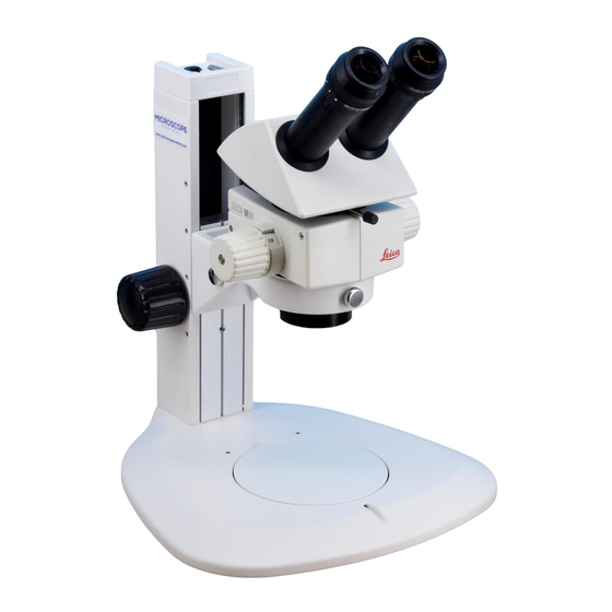
M Series Microscope Overview
Eyepieces and Eyecups
Identification of eyepieces for spectacle wearers with dioptric correction and eyecups.
Eyepiece Fastening Screws
Identifies the screws used for securing the eyepieces.
Ergo Tube Component
Identification of the Ergo tube component.
Optics Carrier Component
Identification of the optics carrier component.
Magnification Changer (Zoom)
Identification of the magnification changer (zoom) component.
Interchangeable Objective
Identification of the interchangeable objective component.
Incident-Light Base
Identification of the incident-light base component.
Column Component
Identification of the column component.
Cable Duct with Cover
Identification of the cable duct with cover component.
Coarse/Fine Focusing Mechanism
Identification of the coarse/fine focusing mechanism.
Setting Interpupillary Distance
Adjusting Interpupillary Distance
Steps to adjust interpupillary distance for a single, circular image field.
Using the Eyepieces
Eyepiece Use (No Glasses)
Instructions for using eyepieces and adjusting eyecups when not wearing glasses.
Eyepiece Use (With Glasses)
Instructions for using eyepieces and adjusting eyecups when wearing glasses.
Dioptric Correction Feature
Information on built-in dioptric correction for eyeglass wearers.
Focusing Operation
Focusing Drive Mechanism
How the focusing drive raises or lowers the microscope for sharp focus.
Focus Adjustment Load Capacity
The coarse/fine adjustment carries a load of up to 15 kg.
Focus Adjustment Resolution
The resolution of the coarse/fine adjustment is 1 µm.
Adjusting Focus Drive Resistance
Focus Resistance Adjustment
Grip outer knobs and turn towards each other to adjust focus movement resistance.
Changing Magnification (Zoom)
Zooming Procedure
Steps to look into eyepieces, focus, and rotate the magnification changer.
Ratchet Steps and Magnification
Controlling Ratchet Steps
Instructions on how to enable or disable ratchet steps for the zoom button.
Magnification and Field of View Info
Information on magnifications and fields of view, referencing page 62 for formulas.
Eyepiece Magnification Factors
Available Eyepiece Specifications
Details on available eyepieces, including magnification, diopter correction, and order numbers.
Health and Safety Notes
Infection Transmission Risks
Discusses infection risks from eyepiece contact and prevention methods.
Dioptric Correction
Performing Dioptric Correction
Step-by-step guide for setting dioptric correction to achieve sharp images.
Dioptric Correction and Parfocality
Preparation for Adjustment
Prepare by setting video/phototube and opening diaphragm.
Adjustment Procedure
Steps for setting dioptric correction and parfocality for clear vision at different magnifications.
Graticules
Graticule Usage
Graticules facilitate length measurements and counting, especially without digital camera/software.
Installing Graticules
Procedure for screwing off the insert, clamping the graticule, and replacing the eyepiece.
ErgoTube 10° to 50°
ErgoTube Features
Adjustable viewing angle for ergonomic posture, ESD construction.
ErgoTube Assembly
Assembly is the same as for any other tube (see Page 20).
ErgoTube Handling
Grasp tubes with both hands and adjust the desired tilt.
Photography and Video Capabilities
Digital Documentation Importance
Importance of digital documentation for presenting results and measurements.
Camera Adapters
Adapters for using third-party cameras with trinocular tubes.
Leica DFC Cameras
Leica DFC cameras offer control, measurement, and evaluation for photography.
Leica Application Suite (LAS)
LAS suite controls microscope, illuminator, stages, cameras for digital extension.
Photo Tubes and C-Mounts
C-Mount Camera Application
C-mount interface for connecting cameras ensures optimum image rendering.
C-Mount Adapter Magnification
Matching adapter magnification to sensor format for optimal field of vision.
Shading Correction Feature
Unwanted corner shading can be corrected using camera software's 'Shading function'.
Third-Party Camera Connection
Connecting third-party cameras using T2 bayonet adapters.
Video and Phototubes HD F & HD V
Optimized for Digital Cameras
Optimized for adapting digital cameras for image acquisition.
HD V Separation Ratios
HD V offers three separation ratios for stereoscopic observation and recording.
HD F Features
HD F has fixed 50% separation for 3D observation and live monitor projection.
Types of Objectives
Achromatic Objectives
Achromatic objectives suited for high-contrast structures; variants available.
Planachromatic Objective 1x
Recommended for overall image quality, providing sharp, contrast-rich fields.
Long Focal Length Objectives
Available for special applications requiring long working distances.
Leica LED3000 NVI™ Illumination
Intensity Adjustment
Illuminator intensity can be adjusted in 10 increments.
Control Options
Can be controlled via Leica Application Suite (LAS) or Leica SmartTouch.
Safe Illumination Use
Switch on illuminator before looking through eyepieces due to brightness.
Adjusting Brightness
Briefly press the + or - buttons to adjust brightness.
Switching Off Illuminator
Briefly press the power button to switch off the illuminator.
Leica LED5000 CXI Illumination
Intensity Adjustment
Illuminator intensity can be adjusted in 10 increments.
Control Options
Can be controlled via Leica Application Suite (LAS) or Leica SmartTouch.
Magnification Increase
Using the LED5000 CXI results in an increased magnification level of 1.5x.
Vignetting at Low Magnification
Vignetting may occur at low magnification; it is normal and not a malfunction.
Safe Illumination Use
Switch on illuminator before looking through eyepieces due to brightness.
Adjusting Brightness
Briefly press the + or - buttons to adjust brightness.
Switching Off Illuminator
Briefly press the power button to switch off the illuminator.
Leica M50 Dimensions
M50 with Small Incident-Light Base
Dimensional drawing of Leica M50 with small incident-light base and 45° binocular tube.
Leica M50 Dimensions
M50 with Large Incident-Light Base
Dimensional drawing of Leica M50 with large incident-light base and ErgoTube® 45°.
Leica M50 Dimensions
M50 with Swinging-Arm Stand
Dimensional drawing of Leica M50 with small swinging-arm stand and 45° binocular tube.
Leica M60 Dimensions
M60 with Large Incident Light Base
Dimensional drawing of Leica M60 with large incident light base and 45° binocular tube.
Leica M80 Dimensions
M80 with Large Incident-Light Base
Dimensional drawing of Leica M80 with large incident-light base and 45° binocular tube.
Leica M80 Dimensions
M80 with Transmitted-Light Base
Dimensional drawing of Leica M80 with transmitted-light base and ErgoTube®.
Leica M80 Dimensions
M80 with Swinging-Arm Stand
Dimensional drawing of Leica M80 with standard swinging-arm stand and 45° binocular tube.
Leica M80 Dimensions
M80 with LED2500
Dimensional drawing of Leica M80 with LED2500 and binocular ErgoTube®.
Leica M80 Dimensions
M80 with Universal Stand & XL Extension
Dimensional drawing of Leica M80 with universal stand, XL extension and binocular ErgoTube™.
Calculating Magnification and Field of View
Magnification Calculation Parameters
Defines parameters for calculating total magnification: MO, ME, Z, q, r, NFOV.
Magnification Calculation Example
Provides an example calculation for total magnification in a binocular tube.
Field of View Calculation Example
Provides an example calculation for field of view diameter in the specimen.
Care, Maintenance, and Contact
Warranty Benefits
Details warranty coverage for faults in materials and manufacture.
Contact Information
Provides contact information for service, representation, and email support.
Essential Care Instructions
Protects microscope from moisture, fumes, acids, and oils; prohibits disassembly.
Care, Maintenance, and Contact (Continued)
Protection from Dirt
Tips for protecting the microscope and accessories from dust and dirt.
Cleaning Polymer Components
Advice on cleaning polymer components safely to avoid damage.
Permitted Cleaning Measures
Methods for cleaning the microscope using water, alcohol, or rubber bulbs.
Need help?
Do you have a question about the M50 and is the answer not in the manual?
Questions and answers