Sign In
Upload
Download
Table of Contents
Contents
Add to my manuals
Delete from my manuals
Share
URL of this page:
HTML Link:
Bookmark this page
Add
Manual will be automatically added to "My Manuals"
Print this page
×
Bookmark added
×
Added to my manuals
Manuals
Brands
Supermicro Manuals
Motherboard
X9QR7-TF+
User manual
Supermicro X9QR7-TF+ User Manual
Hide thumbs
1
2
3
4
5
Table Of Contents
6
7
8
9
10
11
12
13
14
15
16
17
18
19
20
21
22
23
24
25
26
27
28
29
30
31
32
33
34
35
36
37
38
39
40
41
42
43
44
45
46
47
48
49
50
51
52
53
54
55
56
57
58
59
60
61
62
63
64
65
66
67
68
69
70
71
72
73
74
75
76
77
78
79
80
81
82
83
84
85
86
87
88
89
90
91
92
93
94
95
96
97
98
99
100
101
102
103
104
105
106
107
108
109
110
111
page
of
111
Go
/
111
Contents
Table of Contents
Troubleshooting
Bookmarks
Table of Contents
About this Motherboard
Conventions Used in the Manual
Contacting Supermicro
Table of Contents
Chapter 1 Overview
Motherboard Layout
Motherboard Features
Peripheral Devices
System Block Diagram
Processor and Chipset Overview
Special Features
PC Health Monitoring
ACPI Features
Power Supply
Super I/O
Advanced Power Management
Intel ® Intelligent Power Node Manager (IPNM)
Management Engine (ME)
Overview of the Nuvoton WPCM450 Controller
WPCM450R DDR2 Memory Interface
WPCM450R PCI System Interface
Other Features Supported by the WPCM BMC Controller
Chapter 2 Installation
Standardized Warning Statements
Product Disposal
Static-Sensitive Devices
Processor and Heatsink Installation
Installing a Passive Cpu Heatsink
Removing the Heatsink
Installing and Removing the Memory Modules
Installing & Removing Dimms
Removing Memory Modules
Motherboard Installation
Tools Needed
Location of Mounting Holes
Installing the Motherboard
Control Panel Connectors and I/O Ports
Back Panel Connectors and I/O Ports
Back Panel I/O Port Locations and Definitions
Serial Ports
Video Connection
Universal Serial Bus (USB)
Ethernet Ports
Unit Identifier Switch
Front Control Panel
Front Control Panel Pin Definitions
NMI Button
Power LED
Hdd Led
NIC1/NIC2 LED Indicators
Overheat (Oh)/Fan Fail/Pwr Fail/Uid LED
Power Fail LED
Reset Button
Power Button
Connecting Cables
Power Connectors
Fan Headers
Chassis Intrusion
Internal Speaker
Power Led/Speaker
Overheat Led/Fan Fail
DOM Power Connector
Power SMB (I 2 C) Connector
IPMB Header
T-SGPIO1/2 Headers
Jumper Settings
Explanation of Jumpers
LAN Ports Enable/Disable
CMOS Clear
Watch Dog Enable/Disable
VGA Enable
BMC Enable
Management Engine (ME) Recovery
Manufacturer Mode Select
SAS Enable
BMC Reset Enable
Onboard LED Indicators
GLAN Leds
IPMI Dedicated LAN Leds
BMC Heartbeat LED
Unit Identification Switch/Led
2-10 Serial ATA Connections
Serial ATA Ports
SAS2 Ports
Chapter 3 Troubleshooting
Troubleshooting Procedures
System Boot Failure
Memory Errors
When the System Becomes Unstable
Technical Support Procedures
Battery Removal and Installation
Frequently Asked Questions
Returning Merchandise for Service
Chapter 4 BIOS
Introduction
Main Setup
Advanced Setup Configurations
Power Configuration
Cpu Configuration
Cpu Power Management Configuration
Chipset Configuration
North Bridge
Integrated Io Configuration
Qpi Configuration
DIMM Configuration
South Bridge Configuration
Sata Configuration
Super Io Configuration
Serial Port 1 Configuration
Serial Port 2 Configuration
Serial Port Console Redirection
Console Redirection Settings
Console Redirection Settings (for Ems)
Acpi Settings
Event Logs
Ipmi
Bmc Network Configuration
Boot
Security
Save & Exit
Appendix A BIOS Error Beep Codes
BIOS Error Beep Codes
Appendix B Software Installation Instructions
B-1 Installing Software Programs
Configuring Superdoctor® 5
B-2 Configuring Superdoctor® 5
Advertisement
Quick Links
1
About this Motherboard
2
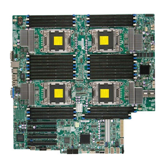
Motherboard Layout
3
Processor and Chipset Overview
4
Installing and Removing the Memory Modules
Download this manual
X9QR7-TF+
X9QRi-F+
USER'S MANUAL
Revision 1.1a
Table of
Contents
Previous
Page
Next
Page
1
2
3
4
5
Advertisement
Table of Contents
Need help?
Do you have a question about the X9QR7-TF+ and is the answer not in the manual?
Ask a question
Questions and answers
Related Manuals for Supermicro X9QR7-TF+
Motherboard Supermicro X9QRi-F+ User Manual
(111 pages)
Motherboard Supermicro Supero X9SRi User Manual
(109 pages)
Motherboard Supermicro Supero X9SRH-7TF User Manual
(115 pages)
Motherboard Supermicro Supero X9DRi-LN4F+ User Manual
Revision 1.1a (113 pages)
Motherboard Supermicro X9DRD-LF User Manual
X9drd-if/lf motherboard (115 pages)
Motherboard Supermicro X9DRW-3F User Manual
(113 pages)
Motherboard Supermicro X9DRW-3F User Manual
(109 pages)
Motherboard Supermicro X9SRW-F User Manual
X9srw series (104 pages)
Motherboard Supermicro Supero X9SPU-F User Manual
(107 pages)
Motherboard Supermicro Supero X9SCA User Manual
Super micro - x9sca server motherboard (107 pages)
Motherboard Supermicro X9SCA Quick Manual
Workstation/server mainboard (38 pages)
Motherboard Supermicro Supero X9SCM-F User Manual
Super micro - x9scl-f desktop motherboard (105 pages)
Motherboard Supermicro Supero X9SCL-F User Manual
Super micro - x9scl-f desktop motherboard (105 pages)
Motherboard Supermicro X9SCM User Manual
Super micro - x9scl-f desktop motherboard (105 pages)
Motherboard Supermicro X9DRG-OF-CPU User Manual
X9drg-of platform (119 pages)
Motherboard Supermicro X9DRW-CF31 User Manual
(111 pages)
This manual is also suitable for:
X9qri-f+
Table of Contents
Print
Rename the bookmark
Delete bookmark?
Delete from my manuals?
Login
Sign In
OR
Sign in with Facebook
Sign in with Google
Upload manual
Upload from disk
Upload from URL


Need help?
Do you have a question about the X9QR7-TF+ and is the answer not in the manual?
Questions and answers