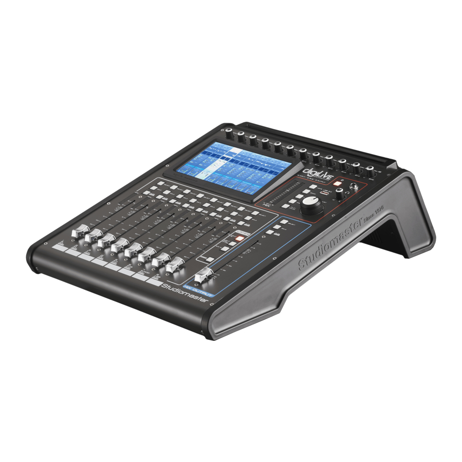
Studiomaster digiLiVE, digiLiVE 16 Manual
- Quick start manual (36 pages) ,
- Quick start manual (36 pages)
Advertisement
Introduction
This Quick Start Guide is intended to help you do just that —to get going with your digiLiVE as quickly as possible. The Guide will show you how to connect your microphones, instruments or other audio sources to the console, how to connect speakers in various ways and how to create a basic mix. It goes on to show you how to enhance your mix by adding gating, compression and reverb, and explains how your digiLiVE can be used as a monitor mixer. Finally, it shows you what to do to control your digiLiVE remotely from a compatible iOS device.

This Quick Start Guide is not intended as an alternative or replacement for the full digiLiVE User Guide, which will either be in the box with the console, or available to you as a free download. As you work through the simple operating examples in the Quick Start Guide, you'll almost certainly notice that the console includes a great many features and possibilities that are not covered here. Once you've mastered the basic principles of operation explained in the Quick Start Guide, you should refer to the User Guide for full details of how to use all the additional facilities.
Unpacking your digiLiVE
Unpacking the digiLiVE you'll find the following (in addition to this Quick Start Guide):
digiLiVE console
Console PSU
IEC power cable
Wi-Fi dongle
User Guide*
* may alternatively be available as a download from www.studiomaster.com
Powering your digiLiVE
Your digiLiVE is powered from the 12 V DC power supply (PSU) packed separately in the carton. Never use any other PSU: your warranty will be invalidated if you do. Connect the PSU to the AC mains supply with the cable supplied; it can operate on mains voltages from 100 V to 240 V. When the PSU is connected to AC mains, a blue LED on the PSU lights. The DC output cable should be plugged in to the 12V/DC INPUT socket on digiLiVE's rear panel.

Once connected, digiLiVE starts its boot-up sequence as soon as you turn the AC mains on; this takes approximately 30 seconds. The Power button  has several functions:

A short press (less than 3 seconds) when the console is ON places it in SAFE mode. The screen and all other displays turn off and the controls become inoperative, but audio will continue to be passed with all console settings retained; A short press when the console is in SAFE mode returns it to its normal operating state; A long press (more than 3 seconds) when the console is ON turns it off; A long press (more than 3 seconds) when the console is OFF switches it back on. Whenever digiLiVE powers down, all current console settings are saved. Next time you power up, digiLiVE will have exactly the same settings you last used.
Connecting speakers
Connect powered speakers to the two rear panel XLR sockets MIX OUTPUT L & R using suitable cables. All the main outputs on digiLiVE are at standard line level and are electronically balanced. If you're using passive speakers with one or more separate amplifiers, connect digiLiVE's outputs to the amplifier inputs.
Connection to passive speakers

Connection to active speakers

NOTE: It is always good practice to turn on interconnected audio devices in sequence. In this case, turn digiLiVE on first, then turn on your powered speakers or power amplifier(s). When powering down, turn the speakers or amplifier off first, then turn digiLiVE off. Observing this sequence will avoid nasty loud bangs or thumps from the speakers.
ADJUST, MUTE and SOLO
In the Application Examples in this Quick Start Guide, you'll need to navigate around digiLiVE's touch-sensitive screens, make selections and adjust various parameters. Most digiLiVE adjustments —apart from fader movements, mutes, etc. - can be made using the large rotary ADJUST knob. The parameter being adjusted will be indicated on-screen by a yellow border around its control; to select a parameter for adjustment, touch its control on the screen. In the example below, the ADJUST knob will pan the signal in Channel 1 between the left and right stereo channels.

Press a channel MUTE button to mute the channel and again to unmute. You can plug headphones into the socket marked  and use the SOLO buttons to listen to one or more input channels while setting up the mix. Pressing SOLO does not alter the main output mix.
Application Examples
The examples shown here use digiLiVE's basic "out of the box" factory default settings. All of the situations described can be expanded upon in various ways by using digiLiVE's many additional features; please consult the User Guide for more detailed descriptions.
Always start setting up your live sound application with digiLiVE's faders fully closed (at their bottom position) and all the rotary GAIN controls (at the top of the mixer) fully anticlockwise. This should ensure that no bangs or thumps will be heard from your system while you're setting everything up.
Application Example 1 —solo performer
This simple application would be suitable for a solo performer, e.g., a singer/instrumentalist. It would also be appropriate for an AV situation such as in a school classroom, or anywhere a presenter is using a laptop or similar audio source as part of his/her presentation.

Connecting up
Connect your speakers or power amplifier to the MIX OUTPUT L & R sockets as described previously.
Plug the vocal microphone into MIC 1 input. Note Inputs MIC 1 to MIC 4 are "Combo" type sockets which can accept either a male XLR connector or a jack plug (TRS or T R). Microphones intended for live use will usually be the dynamic type, but in some AV situations condenser mics may be in use; in this case, phantom power will need to be turned on for this input channel (see below).
Use Input MIC 2 for the instrument. Acoustic instruments such as acoustic guitars will need to be mic'd up. An electroacoustic guitar can either be connected directly using a standard guitar lead if it has sufficient output level, or via a Dl box. For amplified instruments, place a mic in front of the amplifier or use a Dl box between the instrument and amplifier to obtain a mic level signal; alternatively, the amplifier may have a "Line Out" socket which can be plugged into the mixer input directly.
If you need to use a stereo source such as a laptop, tablet or similar audio device, it is most easily connected to STEREO input 2, which is available both in the form of a 3.5 mm jack socket and separate left and right 1/4"jack sockets.
Making a mix
digiLiVE's default configuration allows you to create a stereo mix simply by setting input channel gain and then opening the channel and main faders. On switching on, INPUT 1-8 is selected in the Layer section (note the button is lit), so the input channel faders, MUTE, SOLO and SELECT buttons control Inputs 1 to 8, and the screen display shows Channels 1 to 8.

If you are using a condenser mic, press the SELECT button for Channel 1, and then tap the Input Stage area of the highlighted channel (the topmost area, labelled Mic IN).

Touch the 48V button to enable phantom power for Channel 1. Touch the red cross (top right-hand corner of the screen) to return to the Channels 1 to 8 page.

The 48V indicator at the top of the on-screen channel strip turns to red to remind you that phantom power is on.
Only turn phantom power on when condenser mics are in use. Do not turn it on for any other type of source (however, phantom-powered active Dl boxes are an exception to this rule).
Adjust the GAIN control for Channel 1 while speaking into the mic. You will see an indication on Channel 1 's input meter, which is duplicated by a smaller on-screen meter. A good setting is when the meter just turns yellow on loud passages.

Set Channel I's fader to about the zero mark and move the MIX OUTPUT fader upwards. You should hear the vocal mic when speaking into it, and see a level indication on the MD( meters. These meters monitor the console's output, which is feeding the speakers. Repeat the above procedure for Channel 2, which is receiving the signal from the instrument. If you are using the STEREO 2 input for an audio source as described in "Connecting up" above, press the LAYER button marked INPUT 9-12 ST-USB.

The input channel faders, MUTE, SOLO and SELECT buttons now control the remaining input channels and the screen follows the selection. STEREO 2 is controlled by Fader 6: note that the panel is marked ST2 adjacent to the fader.

Set the input gain and open the channel fader in the same way as described for Channels 1 and 2. Channels on different layers are completely independent; you merely have to switch between layers to access the controls for each.
Application Example 2 —small band
Creating a stereo mix for a small band is simply an extension of Application Example 1. This example would also be suitable for applications such as Houses of Worship. digiLiVE has 12 mono channels to which microphones or line level sources can be connected using XLR connectors: the first four of these can also accept 1/4"jack plugs. In addition to these 12, there are also two stereo channels (accessed via Layer 2). Connecting up Amplifying a band will typically involve microphones, Dl boxes and line level sources. Connect the various sources to the rear panel XLR/Combi inputs: bear in mind that Channels 1 to 8 are on the first fader layer while Channels 9 to 12 and the stereo channels are on the second, so it may be convenient for mixing to have critical audio sources on the same layer. Stereo line sources (such as synths or DJ decks) may be connected to the rear panel inputs STEREO 1 or STEREO 2.

Enable phantom power as necessary for any condenser mics or phantom-powered active Dl boxes as described in Application Example 1.
Making a mix
The factory default settings of digiLiVE let you mix directly to the stereo output, so it is only necessary to adjust the GAIN controls for each input in use and open the input and MIX OUTPUT faders.

White bars indicate fader positions (0 dB in this example)

ST1 and ST2 faders are also set to 0 dB.
Application Example 3 —adding a monitor mix
A small band may require one or more monitor mixes in order that band members can hear themselves and other players as they wish. digiLiVE lets you create up to six additional mono monitor mixes.
Connecting Up
Using the small band setup in Application Example 2, connect powered "wedge" monitors (or the radio transmitters of an in-ear monitoring system) to any of the XLR OUTPUTS 1 to 6. For simplicity, we have just added a single monitor mix (using OUTPUT 1) for the lead singer in the example shown: additional monitors may be added in exactly the same way using further outputs.

OUTPUTS 1 to 6 are electrically identical (balanced, same level) to the two MIX OUTPUTS.
Making a monitor mix
The main PA speakers use digiLiVE's L & R mix busses, which with the console's default routing, are connected directly to the MIX OUTPUTS. To create a separate monitor mix, one of digiLiVE's further eight mix busses is also used.
With the main screen for Channels 1 to 8 displayed, press the SELECT button for the lead singer's mic (we assume this is Ch. 1).
Touch the blank area above the CH 1 ident strip.

This opens the Bus Send sub-page for Channel 1.

Touch (switch on) the Bus 1 button: this sends the mic signal to the bus. Drag the on-screen Bus 1 fader to zero.

Note the PreFader button; this means that the level sent to the monitor will be independent of the channel fader setting. You can continue to adjust your FOH mix without altering the monitor mix. Close the Bus Send sub-page. You have now set a "send" level from the input channel. Next you have to turn up the Bus Master level to set the level that actually leaves the console. Press the BUS 1-8 LAYER button.

Note that the Bus 1 channel strip now shows that it is receiving a send from Channel 1: the small blue bar indicates the level set in Step 4. Raise the fader (which now controls Bus 1 's output level); you should be able to hear the vocal mic in the monitor.
Press the INPUT 1-8 LAYER button to return to the Input Channels Page. Note that Channel 1 now also has a small blue bar indicating the level that is being sent to Bus 1.

If the lead singer needs to hear other performers in his/her monitor mix, repeat Steps 1 to 4 above for each of the other vocalists or instruments needed. For example, if the singer needs to hear the electroacoustic guitar in the example, select Input Channel 4 in Step 1, and send some of its signal to Bus 1 in exactly the same way. You can build up a monitor mix like this with as many instruments as required. The overall level being fed to the monitor is controlled by Fader 1 in the Bus 1-8 layer: the individual contributions to the monitor mix are controlled by the Bus 1 Send levels on the Routing pages for each input channel.
Application Example 4 —using digiLiVE as a dedicated monitor console
digiLiVE may also be used as a dedicated monitor console if the band has a separate FOH mixer or is using the house PA system.
Connecting up
In this situation, all eight outputs (OUTPUTS 1 to 6 and MIX OUTPUTS L & R) are available for use as monitor feeds. Therefore you can create up eight mono or four stereo monitor mixes, or a combination of the two.

In the example shown, we are using four powered wedge monitors are at the front of the stage, plus two side fills; the lead vocalist is using an in-ear monitoring (IEM) system. Connect the wedge monitors to OUTPUTS 1 to 4, the IEM transmitter to OUTPUTS 5 and 6 and the side fills to MD(OUTPUTS L and R.
Making the mix
digiLiVE's faders have a fourth "layer" or mode - SENDS, which works in a different manner to the other layers, but is ideal for this application. To select Send mode you must first select an input channel by pressing its SELECT button. Selecting SENDS only affects the faders and MUTE buttons; the screen display remains unchanged.
When Send mode is selected, the faders become the Bus send level controls for the selected input channel: Fader 1 controls the level sent to Bus 1, Fader 2 controls the level sent to Bus 2 and so on. In this layer only, the MUTE buttons become "ON" buttons: press Bus 1's MUTE button to turn the output on. Once on, a small blue "Bus 1 " bar appears in the send section of the channel indicating the send level.

Touching this section opens up the bus send display for channel 1, providing increased detail for all the channel's bus sends.

It is now easy to set how much of the instrument or vocal in the input channel should go to each of the busses, and thus to each output. You can "scroll through" Channels 1 to 8 by pressing the SELECT buttons in turn; Then by selecting the second layer (INPUT 9-12 ST-USB) the remaining input channels.

Application Example 5 —Enhancing the mix
Adding EQ
You will probably want to adjust the equalisation (EQ) on one or more inputs to optimise sound quality.
Each digiLiVE input channel has a 4-band parametric EQ section. Until you make an adjustment, channels have a "flat" frequency response. To access the EQ controls for any channel, touch the EQ area of its channel strip: the EQ sub-page opens.

Each of the four bands — High, High Mid, Low Mid and Low - can be adjusted for cut or boost (Gain), centre frequency (Freq) and bandwidth (Q). You can adjust the EQ in several ways: Tap the Gain, Freq or Q on-screen control and use the ADJUST knob; Tap the Gain, Freq or Q control and move a finger around the on-screen rotary control in a "dialling" action; Tap one of the circled numbers on the EQ curve to select a band and use your finger to drag the curve: vertically for cut or boost, horizontally for centre frequency. Note you can't adjust bandwidth using this method. You can cancel an EQ curve by tapping the Flat button; tapping the Bypass button has the same audible effect, but a second tap will reinstate the EQ settings. Note that a miniature version of the EQ curve for each input is displayed on the main channel page.

Compressing vocals
Each digiLiVE input channel has a two-section dynamics processor: a noise gate and a compressor. Adding compression to a vocal mic will aid audibility, maintain a good level and help with poor mic technique. (You can of course add compression to any audio source you like, but a vocal mic is a common application.)
To access the dynamics controls for any channel, touch the dynamics area of its channel strip to open the Dynamics sub-page.

To enable the compressor section, tap its IN button. The two main controls for adjusting how much compression is applied are Threshold and Ratio. You can either tap a control and then use the ADJUST knob, or just use your finger to move the on-screen slider. In general terms, the lower the Threshold and the higher the Ratio, the more the signal will be compressed. The graph depicts output level (vertical axis) against input level (horizontal) and shows you how the compressor is currently set up.

The Reduction meter to the right of the graph gives you an idea of how hard the compressor is working; as you increase Ratio, lower Threshold or increase the input signal (either by turning the channel GAIN control up or just singing louder), more Reduction will be indicated. When Ratio is more than 10 or so, the Compressor effectively becomes a Limiter, and the output level will not exceed the value set with the Gain control. The Attack and Release controls control how fast the compressor operates and are best adjusted by ear: their optimum settings will depend on the type of vocal. Depending on the various settings, compression can have the effect of making the signal sound quieter; use the Gain control to bring the level back up to where it needs to be in the mix.
Gating a snare drum
A very common use for a noise gate is to apply gating to a snare drum mic; gating can "tighten up" the drum sound and help to reduce "spillage" into the snare mic from other parts of the drum kit.

Press the Gate IN button to enable it. Adjustment is made in the same way as for the compressor: you can either swipe the on-screen controls or tap them one at a time and use the ADJUST knob. The Gate is an "automatic switch"; signals higher than the level set on the Threshold control pass through the gate, quieter signals are rejected. Adjust the Threshold control so that the snare drum is clearly audible when the drum is hit, but there is no extraneous noise in between snare hits. Threshold is probably most easily set using the channel's SOLO function. You will find that the Attack, Release and Hold settings affect how "tight" the drum sounds; adjust these for the best compromise between a good drum sound and silence in the gaps between the hits. The Depth control sets how completely the gate shuts off "in the gaps"; a higher (negative) value gives a quieter gap. The graph display works differently to that in the Compressor section; the horizontal axis is "time", and the curve represents how fast the gate opens and closes when it is triggered.

The Depth meter to the right of the graph shows you what the gate is doing; the meter will show O dB when the gate is triggered and -80 dB when fully closed: note that it also gives you a clear idea of how the Attack, Hold and Release settings affect the operation. Note that a miniature version of the dynamics section graphs for each input is displayed on the main channel page.

Adding reverb to your vocals
Singers' voices are always enhanced by the addition of some reverb: correctly set, it adds depth and colour and even helps to conceal anything slightly off-key!
digiLiVE has eight digital effects (FX) processors, including two independent reverb units. To add reverb to a vocal:
Press the SELECT button of the relevant input channel and then tap the topmost area of the highlighted channel (Mic IN)
In the Insert section, tap the Reverb 1 button

You will now hear that reverb has been added to the selected input channel. The FX processors have their own control pages: to adjust the amount and nature of the reverb, Press the SET-UP button On the SET-UP page, tap the FX button on the left Double-tap Reverb 1

Either tap a control and then use the ADJUST knob, or use a finger to move the on-screen control: use a "dialling" action for the rotary knobs. The "amount" of reverb is controlled by the Wet/Dry slider, and the reverberation time by the Time control. Tap the arrow in the Type text box to open a list of reverb programs:

Six algorithms are available, four simulating a particular type of "real world" space, and two simulating mechanical reverb plates. The nature of the reverb can be modified further by altering its EQ: separate LF and HF swept shelving filters (labelled LS and HS respectively) are provided. The Gain controls set the amount of cut or boost; the Freq controls set the filter's shelving frequency. The two graphs give a visual indication of the frequency response:

Pre Delay may also be added: this delays the start of the reverberation without affecting the original "dry" signal.
Note: An alternative method of assigning reverb is to apply it to one of the STEREO ouput busses. All channels that require reverb can then be routed to that STEREO output bus. Full details can be found in the User Guide.
Remote Control of the console from an iOS device
You can control digiLiVE from an iOS device running iOS v8 or higher: any iPad model running this OS should be compatible. Your digiLiVE is supplied with a USB WiFi dongle; plug this into the rear panel USB port.
The DigiLive app can be from the Apple App Store in the usual way. Search the store for "Studiomaster Digilive".
You will need to set up a WiFi hotspot on the digiLiVE to establish communication between the iOS device and digiLiVE. To do this,
Press the SET-UP button
On the screen, tap the Setup button

Select Setup Wi-fi, followed by More...
Select Portable hotspot, followed by Setup Wi—Fi hotspot

Enter a new SSID and password (in this example the SSID is DigiLive1)

Tap the Save button
On the Settings screen, tick the Portable Wi—fi hotspot check box.

Press the BACK button to return to the digiLiVE mixer pages
Once you've downloaded the DigiLive app to your iOS device, perform the following steps:
Open the Settings window
Select the WiFi tab, choose DigiLive1 and enter the password.
Open the DigiLive app

Press NetScan to list available mixers (the system can access multiple mixers, but only one at a time): the default mixer name is "0K".

Select the mixer named "0K" and press
Connect The DigiLive app is now available for use.

Documents / Resources
References
Download manual
Here you can download full pdf version of manual, it may contain additional safety instructions, warranty information, FCC rules, etc.
Advertisement


Need help?
Do you have a question about the digiLiVE and is the answer not in the manual?
Questions and answers