Advertisement
Quick Links
Advertisement

Related Manuals for Studiomaster DigiLiVe16


Summary of Contents for Studiomaster DigiLiVe16
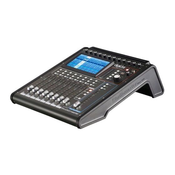
- Page 1 digiLiVE Digital Mixing Console Quick Start Guide Issue 1.0...
- Page 3 Unpacking the digiLiVE you’ll find the following (in addition to this Quick Start Guide): • digiLiVE console • Console PSU • IEC power cable • Wi-Fi dongle • User Guide* * may alternatively be available as a download from www.studiomaster.com...
- Page 4 Powering your digiLiVE Your digiLiVE is powered from the 12 V DC power supply (PSU) packed separately in the carton. Never use any other PSU: your warranty will be invalidated if you do. Connect the PSU to the AC mains supply with the cable supplied; it can operate on mains voltages from 100 V to 240 V. When the PSU is connected to AC mains, a blue LED on the PSU lights.
-
Page 5: Connecting Speakers
Connecting speakers Connect powered speakers to the two rear panel XLR sockets MIX OUTPUT L & R using suitable cables. All the main outputs on digiLiVE are at standard line level and are electronically balanced. If you’re using passive speakers with one or more separate amplifiers, connect digiLiVE’s outputs to the amplifier inputs. - Page 6 ADJUST, MUTE and SOLO In the Application Examples in this Quick Start Guide, you’ll need to navigate around digiLiVE’s touch-sensitive screens, make selections and adjust various parameters. Most digiLiVE adjustments – apart from fader movements, mutes, etc. - can be made using the large rotary ADJUST knob.
-
Page 7: Application Examples
Application Examples The examples shown here use digiLiVE’s basic “out of the box” factory default settings. All of the situations described can be expanded upon in various ways by using digiLiVE’s many additional features; please consult the User Guide for more detailed descriptions. IMPORTANT: Always start setting up your live sound application with digiLiVE’s faders fully closed (at their bottom position) and all the rotary GAIN controls (at the top of the mixer) fully anticlockwise. - Page 8 Connecting up Connect your speakers or power amplifier to the MIX OUTPUT L & R sockets as described previously. Plug the vocal microphone into MIC 1 input. Note Inputs MIC 1 to MIC 4 are “Combo” type sockets which can accept either a male XLR connector or a jack plug (TRS or TR). Microphones intended for live use will usually be the dynamic type, but in some AV situations condenser mics may be in use;...
- Page 9 If you are using a condenser mic, press the SELECT button for Channel 1, and then tap the Input Stage area of the highlighted channel (the topmost area, labelled Mic IN). Touch the 48V button to enable phantom power for Channel 1. Touch the red cross (top right-hand corner of the screen) to return to the Channels 1 to 8 page.
- Page 10 Adjust the GAIN control for Channel 1 while speaking into the mic. You will see an indication on Channel 1’s input meter, which is duplicated by a smaller on-screen meter. A good setting is when the meter just turns yellow on loud passages. Set Channel 1’s fader to about the zero mark and move the MIX OUTPUT fader upwards.
- Page 11 The input channel faders, MUTE, SOLO and SELECT buttons now control the remaining input channels and the screen follows the selection. STEREO 2 is controlled by Fader 6: note that the panel is marked ST2 adjacent to the fader. Set the input gain and open the channel fader in the same way as described for Channels 1 and 2. Channels on different layers are completely independent;...
- Page 12 Application Example 2 – small band Creating a stereo mix for a small band is simply an extension of Application Example 1. This example would also be suitable for applications such as Houses of Worship. digiLiVE has 12 mono channels to which microphones or line level sources can be connected using XLR connectors: the first four of these can also accept ¼”...
- Page 13 Enable phantom power as necessary for any condenser mics or phantom-powered active DI boxes as described in Application Example 1. Making a mix The factory default settings of digiLiVE let you mix directly to the stereo output, so it is only necessary to adjust the GAIN controls for each input in use and open the input and MIX OUTPUT faders.
- Page 14 Application Example 3 – adding a monitor mix A small band may require one or more monitor mixes in order that band members can hear themselves and other players as they wish. digiLiVE lets you create up to six additional mono monitor mixes.
- Page 15 Making a monitor mix The main PA speakers use digiLiVE’s L & R mix busses, which with the console’s default routing, are connected directly to the MIX OUTPUTS. To create a separate monitor mix, one of digiLiVE’s further eight mix busses is also used. 1.
- Page 16 4. Touch (switch on) the Bus 1 button: this sends the mic signal to the bus. Drag the on-screen Bus 1 fader to zero. Note the PreFader button; this means that the level sent to the monitor will be independent of the channel fader setting.
- Page 17 Press the INPUT 1-8 LAYER button to return to the Input Channels Page. Note that Channel 1 now also has a small blue bar indicating the level that is being sent to Bus 1. 6. If the lead singer needs to hear other performers in his/her monitor mix, repeat Steps 1 to 4 above for each of the other vocalists or instruments needed.
- Page 18 Application Example 4 – using digiLiVE as a dedicated monitor console digiLiVE may also be used as a dedicated monitor console if the band has a separate FOH mixer or is using the house PA system. Connecting up In this situation, all eight outputs (OUTPUTS 1 to 6 and MIX OUTPUTS L & R) are available for use as monitor feeds.
- Page 19 When Send mode is selected, the faders become the Bus send level controls for the selected input channel: Fader 1 controls the level sent to Bus 1, Fader 2 controls the level sent to Bus 2 and so on. In this layer only, the MUTE buttons become “ON” buttons: press Bus 1’s MUTE button to turn the output on.
- Page 20 INPUT CHANNEL 1 SELECTED LAYER 1 AND SEND MODE SELECTED FADER LEVELS DEFINE MONITOR MIX TO OUTPUT 1 INPUT CHANNEL 4 SELECTED LAYER 1 AND SEND MODE SELECTED FADER LEVELS DEFINE MONITOR MIX TO OUTPUT 4...
- Page 21 Application Example 5 – Enhancing the mix 5.1 Adding EQ You will probably want to adjust the equalisation (EQ) on one or more inputs to optimise sound quality. Each digiLiVE input channel has a 4-band parametric EQ section. Until you make an adjustment, channels have a “flat”...
- Page 22 Each of the four bands – High, High Mid, Low Mid and Low - can be adjusted for cut or boost (Gain), centre frequency (Freq) and bandwidth (Q). You can adjust the EQ in several ways: Tap the Gain, Freq or Q on-screen control and use the ADJUST knob; •...
- Page 23 5.2 Compressing vocals Each digiLiVE input channel has a two-section dynamics processor: a noise gate and a compressor. Adding compression to a vocal mic will aid audibility, maintain a good level and help with poor mic technique. (You can of course add compression to any audio source you like, but a vocal mic is a common application.) To access the dynamics controls for any channel, touch the dynamics area of its channel strip to open the Dynamics sub-page.
- Page 24 To enable the compressor section, tap its IN button. The two main controls for adjusting how much compression is applied are Threshold and Ratio. You can either tap a control and then use the ADJUST knob, or just use your finger to move the on-screen slider. In general terms, the lower the Threshold and the higher the Ratio, the more the signal will be compressed.
- Page 25 5.3 Gating a snare drum A very common use for a noise gate is to apply gating to a snare drum mic; gating can “tighten up” the drum sound and help to reduce “spillage” into the snare mic from other parts of the drum kit. Press the Gate IN button to enable it.
- Page 26 The Depth meter to the right of the graph shows you what the gate is doing; the meter will show 0 dB when the gate is triggered and -80 dB when fully closed: note that it also gives you a clear idea of how the Attack, Hold and Release settings affect the operation.
- Page 27 5.4 Adding reverb to your vocals Singers’ voices are always enhanced by the addition of some reverb: correctly set, it adds depth and colour and even helps to conceal anything slightly off-key! digiLiVE has eight digital effects (FX) processors, including two independent reverb units. To add reverb to a vocal: Press the SELECT button of the relevant input channel and then tap the topmost area of the •...
- Page 28 You will now hear that reverb has been added to the selected input channel. The FX processors have their own control pages: to adjust the amount and nature of the reverb, Press the SET-UP button • On the SET-UP page, tap the FX button on the left •...
- Page 29 Six algorithms are available, four simulating a particular type of “real world” space, and two simulating mechanical reverb plates. The nature of the reverb can be modified further by altering its EQ: separate LF and HF swept shelving filters (labelled LS and HS respectively) are provided. The Gain controls set the amount of cut or boost;...
- Page 30 USB port. The DigiLive app can be downloaded from the Apple App Store in the usual way. Search the store for “Studiomaster Digilive”. You will need to set up a WiFi hotspot on the digiLiVE to establish communication between the iOS device and digiLiVE.
- Page 31 Select Portable hotspot, followed by Setup Wi-Fi hotspot • Enter a new SSID and password (in this example the SSID is DigiLive1) • Tap the Save button •...
- Page 32 On the Settings screen, tick the Portable Wi-fi hotspot check box. • Press the BACK button to return to the digiLiVE mixer pages • Once you’ve downloaded the DigiLive app to your iOS device, perform the following steps: Open the Settings window •...
- Page 33 Press NetScan to list available mixers (the system can access multiple mixers, but only one at • a time): the default mixer name is “OK”. Select the mixer named “OK” and press Connect • The DigiLive app is now available for use.
- Page 36 STUDIOMASTER Unit 11, Torc:MK, Chippenham Drive, Milton Keynes MK10 0BZ, United Kingdom Tel: +44 (0)1908 281072 Email: enquiries@studiomaster.com Web: www.studiomaster.com...
Need help?
Do you have a question about the DigiLiVe16 and is the answer not in the manual?
Questions and answers