
Related Manuals for Standard Horizon CP170C


Summary of Contents for Standard Horizon CP170C
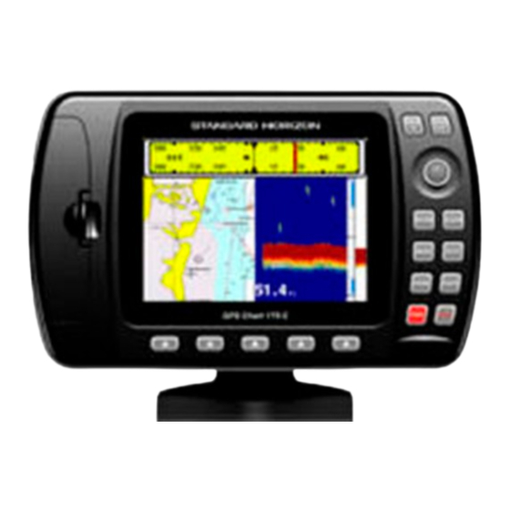
- Page 1 CP160/CP170C GPS Chartplotter Owner's Manual ZOOM ZOOM ENTER CLEAR MENU GOTO MARK ROUTE...
- Page 2 Attenzione! L'esposizione del display ai raggi ultravioletti può accorciare la vita dei cristalli liquidi usati nel vostro plotter cartografico. Questo limite è dovuto alla tecno- logia costruttiva degli attuali display. Evitare inoltre che il display si surriscaldi per non causare una diminuzione di contrasto che, in casi estremi, può...
-
Page 3: Table Of Contents
TABLE OF CONTENTS 1. GENERAL INFORMATION ....................9 1.1 INTRODUCTION ....................9 1.2 IF YOU NEED ASSISTANCE ................9 2. ACCESSORIES ...................... 11 2.1 PACKING LIST ....................11 2.2 OPTIONS ...................... 11 3. CONTROLS AND INDICATORS ..................12 3.1 CONTROLS AND CONNECTIONS ..............12 3.1.1 Soft keys Customization ................ - Page 4 4.2 C-MAP NT INFORMATION .................. 31 4.2.1 Getting Quick Info ..................31 4.2.2 Information Function .................. 32 4.2.3 Getting Port Info ..................32 4.2.4 Getting Tide Info ..................34 4.2.5 Finding Tide Stations ................. 35 4.2.6 Finding Port Services ................. 35 4.2.7 Finding Port by Name ................
- Page 5 4.5.5 Placing Cursor on a Route ................ 50 4.6 MOB FUNCTION ....................50 4.6.1 Inserting MOB .................... 50 4.6.2 Deleting MOB ..................... 50 4.7 USING THE TRACK FUNCTIONS ..............50 4.7.1 Enabling Track storing ................51 4.7.2 Selecting active Track ................51 4.7.3 Displaying Track ..................
- Page 6 Congratulations on your purchase of the GPS CHART 160/ GPS CHART 170C! Whether this is your first chartplotter, or if you have other STANDARD HORIZON equipment, the STANDARD HORIZON organization is committed to ensuring you your enjoyment of this chartplotter. STANDARD HORIZON technical support person-...
-
Page 7: General Information
If your chartplotter does not operate properly, go to the System Test on Section 7.1. Most common operating difficulties can be diagnosed using these tests. If you still need assistance, call STANDARD HORIZON Product Support or your local Dealer, reporting the Software System Information... - Page 8 Figure 1.2 - About Page STANDARD HORIZON Product Support Department may be contacted at 562-404-2700 or via e-mail at marinetech@yaesuusa.com. Page 10 GPS Chart 160/170C...
-
Page 9: Accessories
2.2 OPTIONS If any parts are missing contact the Dealer this chartplotter was purchased from. Accessories and Replacement parts may be ordered from STANDARD HORIZON's parts Department at 562-404-2700 Ext 351 or via the web at www.standardhorizon.com. are available through your local marine Dealer. For additional information on C-MAP Cartography contact 800-424-2627 or visit web site at www.c-map.com. -
Page 10: Controls And Indicators
3. CONTROLS AND INDICATORS NOTE This Section defines each control of the chartplotter. For detailed operating instructions, refer to Section 8. Refer to Figure 3.1 for the location of the following keys and connections. 3.1 CONTROLS AND CONNECTIONS The chartplotter is controlled by using 15 keys: 10 labelled keys are dedicated to specific functions;... - Page 11 ZOOM ZOOM keys There are two different modes to change chart scale "By Zoom" and "By Scale". 'MENU' + "GENERAL SETUP" + 'ENTER' + "ZOOM TYPE" + 'ENTER' + "By Zoom" + 'ENTER' Pressing the 'ZOOM IN' shows more detail of a smaller area, by changing the chart scale and zooming in on your display.
-
Page 12: Soft Keys Customization
GOTO Allows the user to select a Destination point at the cursor or a saved Route or Mark. MARK Places Mark under the cursor position (in Home mode Mark is placed under the ship's position). ROUTE Places Waypoints to make Routes. key and Lamp/Contrast Press 'PWR' to turn the chartplotter On. -
Page 13: Gps Antenna Connector
DIRECTORY (DSC Directory page) DISPLAY (Display page, see Section 3.2.7.1) ISPLAY DATA (Data page, see Section 3.2.7.2) DEPTH TREND (Depth Trend page, see Section 3.2.7.3) EPTH WIND SPEED TREND 'W (Wind Speed Trend page, see Section 3.2.7.4) TEMP TREND (Temp Trend page, see Section 3.2.7.5) SOG TREND (SOG Trend page, see Section 3.2.7.6) USER POINTS LIST... -
Page 14: General
Figure 3.2.1 - Data window layout It is also possible to edit fields shown in every screen configuration. Edit mode is activated directly from the chart display pressing 'MENU' for 3 seconds. Once the Edit mode is active, the first box with the label turns gray and its frame is drawn bold. -
Page 15: Line Text Window
Figure 3.2.1.1 - Charts and general text area When in Home mode the coordinates field shows ship's coordinates; also it is possible to choose the data to be displayed in the four fields 3.2.1.2 Line text window 'MENU' + "GENERAL SETUP" + 'ENTER' + "DATA WINDOW" + 'ENTER' + "1 line small /1 line large"... -
Page 16: Full Chart
Figure 3.2.1.2a - Charts and 2 lines text area As in the previous Figure 3.2.1.2, when in Home mode the coordinates field shows ship's coordinates; the six fields are selectable fields as described in the previous Section 3.2.1. 3.2.1.3 Full chart It is also possible to show the cartography at full screen: 'MENU' + "GENERAL SETUP"... -
Page 17: Highway Page
Figure 3.2.2 - Navigation Data Page 3.2.3 Highway Page 'MENU' + "HIGHWAY" + 'ENTER' press any soft key + 'H ' (if it is present) IGHWAY Shows the 3D Highway and the most relevant navigation information. It is possible to customize all fields shown in the page as described in the previous Section 3.2.1. -
Page 18: Gps Status Page
Shows the Moon phases, Sunrise/Sunset time and Low Water/High Water level at current location. The day can be moved in the calendar by moving the ShuttlePoint knob left/right; use 'ZOOM IN'/'ZOOM OUT' to change the month. Figure 3.2.4 - Celestial Page 3.2.5 GPS Status Page 'MENU' + "GPS"... -
Page 19: Position Request
press any soft key + 'L ' (if it is present) Shows the Distress Call LOG page or Position Request LOG page (it depends which of the two was selected. The default is Distress Call LOG page). Press 'CLEAR' to return to chart display. -
Page 20: Data Page
It is possible to choose the page layout (the number of fields in the page) and the type of data shown in each of the fields in the page as described in the previous Section 3.2.1. If the selected type of data is not received the field shows dashes. Figure 3.2.7.1 - NMEA DISPLAY Page Data selectable are: SOG, COG, DST, BRG, XTE, TTG, ALT, HDOP, VDOP, BOAT SPEED, HEADING, DEPTH, TRIP LOG, WATER TEMP, TRUE WIND SPEED, TRUE... -
Page 21: Wind Speed Trend Page
Figure 3.2.7.3 - Depth Graph Page NOTE Changing time scale will delete all points on the graph. 3.2.7.4 Wind Speed Trend Page 'MENU' + "NMEA DISPLAY" + 'ENTER' + "WIND SPEED TREND" + 'ENTER' press any soft key + 'W ' (if it is present) Shows the graph of the Apparent Wind Speed received from the NMEA Port. -
Page 22: Sog Trend Page
Shows the graph of the Water Temperature received from the NMEA Port. Pressing 'ZOOM IN'/'ZOOM OUT' changes the time scale. Figure 3.2.7.5 - Temp Graph Page NOTE Changing time scale will delete all points on the graph. 3.2.7.6 SOG Trend Page 'MENU' + "NMEA DISPLAY"... -
Page 23: Operation
4. OPERATION 4.1 INITIAL SETUP 4.1.1 Installing/Removing chartplotter Figure 4.1.1 - Installing/removing chartplotter 4.1.2 Cable Wiring P O W E R & I n / O u t C a b l e WIRE COLOR - Description CONNECTION EXAMPLES (Check the equipments owner’s manual connections) BLACK - Battery Ground Negative 12VDC source RED - Positive 12VDC... - Page 24 CONNECTION EXAMPLE for NMEA 1 Horizon SPECTRUM VHF RADIO with DSC Brown Green Green Blue Gray > Brown Blue > DISTRESS Horizon INTREPID VHF RADIO with DSC Green Green Brown Blue > Green NMEA Input - VHF RADIO CONNECTION TO SHOW Brown NMEA Input + >...
-
Page 25: Turning The Chartplotter On And Off
CONNECTION EXAMPLE for NMEA 2/RTCM Horizon MD150 MULTIDATA Black Green Gray Blue > MULTI reset Green NMEA Input/Output - Gray NMEA Output + EXTERNAL NMEA > DEVICE White NMEA Input - > Select the sentences to send by pressing ‘MENU’ + “ADVANCED SETUP” + ‘ENTER’ + “INPUT/OUTPUT” + ‘ENTER’ + “NMEA 2 OUTPUT” + ‘ENTER’ : ‘... -
Page 26: Turning On
PWR + (RED) 10 35 VDC PWR - (BLACK) Figure 4.1.3 - Power On Check also for the correct connection of the GPS antenna. 4.1.3.1 Turning On Press and hold 'PWR' for 1 second. The chartplotter emits one rapid beep sound and the Start-Up pages are opened: Figure 4.1.3.1 - Start-Up pages NOTE... -
Page 27: Selecting The Language
4.1.5 Selecting the Language It is possible to select the Language in which you wish information to be displayed (for screen labels, menus and options, but it does not affect the map information). The default setting is English. 'MENU' + "GENERAL SETUP" + 'ENTER' + "LANGUAGE" + 'ENTER' Choose the Language you want and press 'ENTER' to confirm. -
Page 28: Nmea2/Rtcm Input
Figure 4.1.6.3 - NMEA Sentences 4.1.6.4 NMEA2/RTCM Input Selects the input type among NMEA and RTCM 1200, 2400, 4800, 9600, 19200, 38400 (where the number means the Baud Rate of the RTCM signal). By selecting RTCM the Differential Correction Source is automatically set to External RTCM. If NMEA2/RTCM Input is different from NMEA or RTCM 4800, the NMEA2 Output is stopped and a warning message will be shown. -
Page 29: Removing C-Card
Open the door (see in Figure 3.1), gently push the C-CARD into one of the two slots; push the C-CARD in as far as it will go, then close the door to hold fixed into the slot (as shown in the following Figure 4.1.7.1a). Figure 4.1.7.1a - Inserting/Removing C-CARD (II) 4.1.7.2 Removing C-CARD Open the door and remove the C-CARD out of one of the two slots (as shown in the... -
Page 30: Information Function
To expand information (to obtain all information) about that object press 'ENTER': Figure 4.2.1a - Expanded information 4.2.2 Information Function Place the cursor in any place you want and press 'MENU' + "INFORMATION" + 'ENTER' to obtain a whole screen page where a list of all objects (in a tree structure), found in the range of the cursor, is displayed;... - Page 31 Figure 4.2.3 - Port Info icon The available information is shown in the Quick Info window (if the Info Level setting is Detailed - default setting ) where icons of the available services are shown: Figure 4.2.3a - Quick Info window To expand information about that object press 'ENTER': Figure 4.2.3b - Full Info (I) Select the service you want and press 'ENTER': a detailed information on the services...
-
Page 32: Getting Tide Info
Figure 4.2.3c - Full Info (II) For all countries, where such information exists on the paper chart, you will also see accurately positioned symbols which show where many useful facilities are located. 4.2.4 Getting Tide Info To obtain Tide Info: Figure 4.2.4 - Tide Info icon Place cursor on the Tide symbol, a Quick Info window is opened: Figure 4.2.4a - Quick Info on Tide... -
Page 33: Finding Tide Stations
Figure 4.2.4b - Tide Graph Using the ShuttlePoint knob, it is possible to move the cursor anywhere on the graph and display the time, height (vertical cursor) and draught (horizontal cursor) on a particular graph point. Also use 'ZOOM IN' or 'ZOOM OUT' to go to previous or next day and 'ENTER' to set date (move the ShuttlePoint knob up/down to insert the desired number and move it left/right to move cursor to left/right, press 'ENTER' to confirm). -
Page 34: Finding Port By Name
Figure 4.2.6 - Port Services Use the ShuttlePoint knob to select any facility and press 'ENTER'. By selecting one of the facilities, the list of the nearest ports (up to 10) in which this port facility is present, will be shown on the screen. Figure 4.2.6a - List of the nearest ports Then choose the facility you want and press 'ENTER': Figure 4.2.6b - Info on selected service... -
Page 35: Entering Port Name
'MENU' + "FIND" + 'ENTER' + "PORT BY NAME" + 'ENTER' Figure 4.2.7 - List by name of available ports NOTE A Warning message is shown if: there is no C-CARD inserted; there are no ports on the C-CARD. Use the ShuttlePoint knob to select port; use 'ZOOM IN' and 'ZOOM OUT' to select the next/previous page. -
Page 36: Deleting Mark
4.3.1.2 Deleting Mark Place cursor on Mark Press 'ENTER'. Select "DELETE" and press 'ENTER'. 4.3.1.3 Moving Mark Figure 4.3.1.3 - Moving Mark (I) Place cursor on Mark and press 'ENTER'. Select "MOVE" and press 'ENTER'. By moving the cursor with the ShuttlePoint knob, a dotted line connecting the Mark with the new position is shown: Figure 4.3.1.3a - Moving Mark (II) Press 'ENTER':... -
Page 37: Editing Mark
4.3.1.4 Editing Mark Place cursor on Mark Press 'ENTER'. Select "EDIT" and press 'ENTER'. A window appears to modify name, symbol, (Color - Only for CP 170C) coordinates of the existing Mark (see previous Figure 4.3.1.3) Use the ShuttlePoint knob to select the field. If you have selected name field, press 'ENTER': use the ShuttlePoint knob to insert the character (10 characters max), then press 'ENTER'. -
Page 38: Creating A Route
Figure 4.4.1.1 - Waypoint placing 4.4.1.2 Creating a Route Repeat the "Adding Waypoint" procedure described in the previous Section 4.4.1.1 "Adding Waypoint". The sequence of moving the cursor and pressing 'ROUTE' is continued to create the Route, until you have reached the last Waypoint, your final destination. -
Page 39: Deleting Route
Figure 4.4.1.3 - Deleting Waypoint (I) Press 'ENTER'. Select "DELETE" and press 'ENTER': select "YES" and press 'ENTER' (select "NO" and press 'ENTER' to abort operation). The Waypoint is deleted and a new line between previous and next Waypoint is shown: Figure 4.4.1.3a - Deleting Waypoint (II) 4.4.1.4 Deleting Route Place cursor on Waypoint... -
Page 40: Inserting Waypoint
Figure 4.4.1.5 - Moving Waypoint (I) To place the Waypoint in the new position, choose the new place and press 'ENTER' ('CLEAR' to abort the move), Waypoint appears in the new position: Figure 4.4.1.5a - Moving Waypoint (II) 4.4.1.6 Inserting Waypoint Every time you place the cursor on the segment connecting two existing Waypoints of a Route the following functions are available: insert Waypoint, Report, delete Route. -
Page 41: Editing Waypoint
Figure 4.4.1.6a - Placing Waypoint between two existing ones (II) Once you have positioned the cursor at new location, press 'ENTER' (press 'CLEAR' to abort operation): Figure 4.4.1.6b - Placing Waypoint between two existing ones (III) 4.4.1.7 Editing Waypoint Place cursor on Waypoint Press 'ENTER'. -
Page 42: Finding Information On A Route: Route Report Page
'ENTER': use the ShuttlePoint knob to insert the character (10 characters max), then press 'ENTER'. If symbol field is selected press 'ENTER': a window with 16 different symbols appears: Figure 4.4.1.7a - Edit Waypoint (II): Waypoint symbols Use the ShuttlePoint knob to select the symbol and press 'ENTER'. If selecting coordinates field, press 'ENTER' and then use the ShuttlePoint knob to insert the value, press 'ENTER' to store. -
Page 43: Selecting Route
Figure 4.4.1.8 - Route Report page If there are more than 8 Waypoints shown, use the ShuttlePoint knob to select another page. Selecting Route Place cursor on Waypoint + 'ENTER' + "REPORT" + 'ENTER' + "SELECT" + 'ENTER' Use the ShuttlePoint knob to select the Route identifier and press 'ENTER'. The data related to the selected Route are shown on the screen. -
Page 44: Finding Information On Waypoints: User Points List Page
NOTE Speed and fuel are made by the user to assist in estimating approximate travel time and fuel consumption for each Route. 4.4.1.9 Finding information on Waypoints: User Points List page 'MENU' + "USER POINTS LIST" + 'ENTER' press any soft key + 'L ' (if it is present) Figure 4.4.1.9 - User Points List page If the page contains more than 7 User Points, the list continues in the next pages. -
Page 45: Finding User Point
Figure 4.4.1.9b - User Point icon Otherwise choose "ALL" and press 'ENTER' to show all icons (see Figure 4.4.1.9). Finding User Point 'MENU' + "USER POINTS" + 'ENTER' + "FIND" + 'ENTER' Allows finding the point on the list by entering the User Point name. If "ICON" is set to "ALL"... -
Page 46: Routes
Allows reading User Points from the NMEA input port (NMEA sentence WPL). 4.4.2 Routes The following functions are used for the Route management. The chartplotter handles Routes from 1-20, which are permanently stored in the memory as they are created. Only one Route can be selected for work at any one time. -
Page 47: Goto Function
Saves Route information (NMEA sentences WPT, RTE) received from the NMEA Input port (selectable by the user in the Input/Output menu, Send/Rec Rte & Marks Port item see Section 8). The received Route is saved on the current Route. If the current Route contains data the chartplotter shows a warning window and asks the user if he wants to overwrite the existing Route. -
Page 48: Stopping Goto Navigation
4.5.4 Stopping Goto navigation If the Destination point is already present, when 'GOTO' is pressed a window is shown. Select "STOP" and press 'ENTER' to stop navigating to the current Destination. Otherwise selecting "START" removes the current Destination and places a new one at the cursor position. -
Page 49: Enabling Track Storing
4.7.1 Enabling Track storing 'MENU' + "TRACK" + 'ENTER' + "TRACKING" + 'ENTER' To enable (On) or disable (Off) the Track storing. It is not possible to use the Track storing if you are not receiving a valid fix. The default setting is On. 4.7.2 Selecting active Track 'MENU' + "TRACK"... -
Page 50: User C-Card Menu
When the tracking function is On and the type of Track storing is Time, the chartplotter can store a fix after a defined time. Choose among 1, 5, 10, 30 sec, 1, 5, 10 min. The default setting is 1 sec. 4.8 USER C-CARD MENU The chartplotter allows copying information to a User C-CARD. -
Page 51: Loading File
Select the file name and press 'ENTER'. At first a default name is shown: use the ShuttlePoint knob to insert the name. Press 'ENTER'. Select the data type to save among "MARK", "ROUTE" or "TRACK". NOTE When naming a file, you may have trouble finding a name that uniquely identifies the file's contents. -
Page 52: Formatting User C-Card
4.8.4 Formatting User C-CARD 'MENU' + "USER C-CARD" + 'ENTER' + "FORMAT" + 'ENTER' press any soft key + 'C-C ' (if it is present) + "FORMAT" + 'ENTER' A warning window is shown, select "YES" and press 'ENTER' to confirm the formatting (select "NO"... -
Page 53: Maintenance
5. MAINTENANCE For general troubleshooting, please refer to this TROUBLESHOOTING CHART. TROUBLESHOOTING CHART SYMPTOM PROBABLE CAUSE REMEDY The chartplotter does not The voltage or the polarity Make sure that the correct volt- turn On. may not be correct. age (10-18 volt dc) is present. Check also that the polarity is correct. -
Page 54: Specifications
6. SPECIFICATIONS 6.1 GENERAL Power consumption (CP 160) : 380mA max @12V Power consumption (CP 170C): 800mA max @12V Power supply (CP 160) : 10 - 35 Volt dc, 5 Watt max Power supply (CP 170C) : 10 - 35 Volt dc, 10 Watt max Interface : Input/Output Interface NMEA-0183 Display (CP 160) -
Page 55: Gps Receiver Specifications
6.2 GPS RECEIVER SPECIFICATIONS Receiver : L1, C/A code Channels : 12 Max Solution Update Rate: 1/sec. Cold Start (avg) : < 45 sec. Warm Start (avg) : < 40 sec. Hot Start (avg) : 8 sec. 6.3 GPS ANTENNA SPECIFICATIONS Figure 6.3 - GPS Antenna 6.3.1 Physical Constructions Physical Constructions... -
Page 56: Overall Performance (Antenna Element, Lna & Coax Cable)
Connector : SMA 6.3.3 Overall Performance (antenna element, LNA & coax cable) Center Frequency : 1575.42 Mhz Gain : 25 dB typical. Noise Figure : 2.0 max. Axial Ratio : 3 dB max. Bandwidth : 2MHz min. VSWR : 2.0 max. Output Impedance : 50 Ohm 6.3.4 Enviromental... -
Page 57: Technical
7. TECHNICAL 7.1 SYSTEM TEST If you have connected your chartplotter according to the instructions, and chosen the proper menu selection for your device, and are still having problems with your chartplotter, the extended auto-test should help determine the problem. Make sure the chartplotter is turned Off. -
Page 58: Dim Menu
RAM is physically damaged. Contact your Dealer or STANDARD HORIZON. RAM Clear To clear internal memory. If the chartplotter exhibits unusual operations, or appears to be malfunctioning, it may be possible to correct the problem by clearing RAM. This operation will erase all Marks, Routes, stored Track plots and Destinations. It will also return all selections (Input Data Format, Autopilot selection, etc.) to original... -
Page 59: Serial Ports
Background ROM To test the WorldWideBackground. If there is not a malfunction, the code of the Background and the message "OK" are shown, but if the Background is defective the message "Faulty" is shown. C-CARD Test To test the C-CARD. There are three possible situations: 1. - Page 60 If the data displayed on the screen is unrecognizable, you may have selected the wrong input parameters for your particular receiver, for example, Baud Rate 9600 instead of Baud Rate 4800. Check your receiver manual to be sure that you have selected the proper parameter.
-
Page 61: Terms & Functions
8. TERMS & FUNCTIONS This Section explains the terms that may be unfamiliar to the reader. The symbol indicates that the term is followed only by an explanation, while the symbol indicates that the term is more widely explained; you will also find a brief description on how to select the related menu option, listing the operation a keys sequence with the menu names enclosed between double apices. - Page 62 the area selecting On or Contour options. This is valid also for the categories: FISHING FACILITY, MARINE FARM/CULTURE, MILITARY PRACTICE AREA, RESTRICTED AREA, SEAPLANE LAND- ING AREA. When the area is small, it is identified only by the boundary. The default setting is Contour. 'MENU' + "MAP SETUP"...
- Page 63 Celestial (page) 'MENU' + "CELESTIAL" + 'ENTER' press any soft key + 'C ' (if it is present) ELEST Shows the Moon phases, Sunrise/Sunset time and Low Water/High Water level refer to the current fix. The selection can be moved in the calendar by using the ShuttlePoint knob left/right; use 'ZOOM IN'/ 'ZOOM OUT' to change the month.
- Page 64 'MENU' + "MAP SETUP" + 'ENTER' + "OTHER SETTINGS" + 'ENTER' + "COMPASS" + 'ENTER' Compass (menu) Sets the desired value for Bearing and (Magnetic) Variation, and selects the Calibration page. 'MENU' + "ADVANCED SETUP" + 'ENTER' + "COMPASS + 'ENTER' Complex Object Current official documentation S57 supports "Complex Object".
- Page 65 CTS = Course To Steer The optimum direction the boat should be steered in order to efficiently make headway back to the courseline while also proceeding toward the destination Waypoint. Cultural Features Enables (On) or disables (Off) the displaying of the Cultural Features (any man-made topographic feature as built-up area, buildings, roads, ...).
- Page 66 Delete (File) Deletes file from User C-CARD. 'MENU' + "USER C-CARD" + 'ENTER' + "DELETE" + 'ENTER' press any soft key + 'C-C ' (if it is present) + "DELETE" + 'ENTER' Delete (Route) To delete the selected Route. 'MENU' + "ROUTE" + 'ENTER' + "DELETE" + 'ENTER' + "YES" + 'ENTER' Delete (Track) To clear the stored Track.
- Page 67 (NMEA) Display 'MENU' + "NMEA DISPLAY" + 'ENTER' + "DISPLAY" + 'ENTER' press any soft key + 'D ' (if it is present) ISPLAY It is possible to choose the page layout (the number of fields in the page) and the type of data shown in each of the fields in the page.
- Page 68 Delete: Deletes selection position. Delete All: Deletes all entries. Hide/Show: Allows hiding/showing the selected points on the chart display. The default value of the field is Yes (object shown on the map). Position Request: Shows Position Request LOG Page. When Position Request LOG Page is active this message changes to Distress Call LOG Page.
- Page 69 Correction is not enabled, the ship's position is not changed. The default setting is Off. 'MENU' + "ADVANCED SETUP" + 'ENTER' + "FIX" + 'ENTER' + "FIX CORRECTION" + 'ENTER' Fix Datum Selects the Fix Datum among 130 items (the list of all Fix Datum available is shown in the " Handbook").
- Page 70 HDG = Heading The horizontal direction in which a ship actually points or heads in any moment (see also COG). HDOP = Horizontal Dilution Of Precision It is the index for position-fixing accuracy. The smaller the HDOP value, the more accurately the position can be fixed (see Part B of "...
- Page 71 'MENU' + "ADVANCED SETUP" + 'ENTER' + "INPUT/OUTPUT" + 'ENTER' + "INTERNAL GPS SETUP" + 'ENTER' Keypad Beep Turns On/Off the sound after pressing a key ("beep"). The default setting is On. 'MENU' + "GENERAL SETUP" + 'ENTER' + "KEYPAD BEEP" + 'ENTER' Land Settings (menu) Turns On/Off the display of Natural Features, Rivers &...
- Page 72 of " Handbook"). WGS 1984 is the default Map Datum. 'MENU' + "ADVANCED SETUP" + 'ENTER' + "NAVIGATE" + 'ENTER' + "MAP DATUM" + 'ENTER' Map Orientation Selects the orientation of your chart according to: North Up (the map is shown with North upwards), Course Up (the map is displayed with the currently selected course leg upwards).
- Page 73 Exit from Navigate: move the cursor Navigation (page) 'MENU' + "NAVIGATION" + 'ENTER' press any soft key + 'N ' (if it is present) Shows information compass display, fix position and the most relevant navigation information. Compass ruler and Lat/Lon field are fixed field and cannot be changed.
- Page 74 Pair Selects the pair of stations in the selected TD chain. The default setting is W X. 'MENU' + "ADVANCED SETUP" + 'ENTER' + "NAVIGATE" + 'ENTER' + "COORDINATE SYSTEM" + 'ENTER' + "TD" + 'ENTER' + "Pair" + 'ENTER' Palette Only for CP 170C Selects among Normal, Sun Light and Night Vision.
- Page 75 Reverse (Route) Reversing a Route plan is most typically used to return to the point where the Route originally started. 'MENU' + "ROUTE" + 'ENTER' + "REVERSE" + 'ENTER' Rivers & Lakes Turns On/Off the displaying of Rivers and Lakes. The default setting is On. 'MENU' + "MAP SETUP"...
- Page 76 Soft Key The software keys (or soft keys) are used from the chart screen or from the data pages to select one of the data pages available so allow a faster access to the page selection executable from the Main Menu.
- Page 77 'MENU' + "TRACK" + 'ENTER' + "STEP UNIT" + 'ENTER' STR = Steering The difference between COG and CTS. If COG is 25° and CTS is 30°, then STR is 5° Right. Target In order to tag on the chart the point, towards which the ship is Heading, you can use a special mark, called Target.
- Page 78 after a defined time. Choose among 1, 5, 10, 30 sec, 1, 5, 10 min. The default setting is 1 sec. 'MENU' + "TRACK" + 'ENTER' + "TIME" + 'ENTER' Time Format Sets the preferred time between 12 hour and 24 hour. The default setting is 12 hour. 'MENU' + "GENERAL SETUP"...
- Page 79 press any soft key + 'C-C ' (if it is present) User Point Place on the chart identified by its coordinates and displayed on the screen with a reference symbol (see Mark, Waypoint). User Points Finds Marks or Waypoints saved by the user. 'MENU' + "FIND"...
- Page 80 Figure 8l - Wind Speed Graph Page WGS-84 = World Geodetic System 1984 Coordinate System or Datum developed by the Defense Mapping Agency (DMA) (see Part A of " Handbook"). XTE Alarm Disables the XTE Alarm (Off) or selects the desired value. The default setting is Off. 'MENU' + "ADVANCED SETUP"...
-
Page 81: Analytical Index
ANALYTICAL INDEX Chart ..........15, 65 About Page ........9, 63 Chart Boundaries ........65 Accessories ........... 11 Chart Generation ........65 Active Track ......51, 63, 80 Chart Settings (menu) ......65 Advanced Setup ........63 Chartplotter ..........12 Alarm ............. - Page 82 Deleting File ........... 53 Getting Port Info ........32 Deleting Route ........ 45, 77 Goto ..........38, 71 Deleting Track ........ 51, 80 GPS ........20, 68, 71, 76 Deleting User Point ....... 47 GPS Data Page ......20, 72 Depth ..........
- Page 83 Power On ..........27 Magnetic Deviation ........ 73 Magnetic Variation ......73, 81 Main Menu ..........13 Quick Info ..........31 Man OverBoard ........74 Map Datum ..........73 Map Orien. Resolution ......76 Receive (Route) ........76 Map Orientation ........74 Receiving User Points ......
- Page 84 Turning On ..........14 Target ........47, 71, 79 Target on Cursor ........49 TD ............79 Underwater Objects ....... 80 Technical ..........59 User C-CARD ....30, 52, 70, 80 Temperature .......... 56 User Point ........ 39, 46, 81 Tempt Trend page ......
Need help?
Do you have a question about the CP170C and is the answer not in the manual?
Questions and answers