Nice Era, Era Zero Manual
- Instructions and warnings for installation and use (33 pages) ,
- Fitting instructions (2 pages) ,
- Instructions and warnings for installation and use (13 pages)
Advertisement
PRODUCT DESCRIPTION AND INTENDED USE
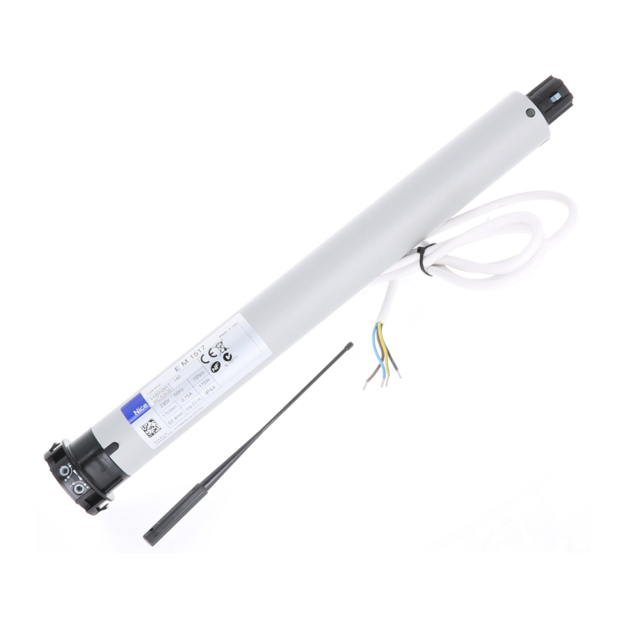
This product is a tubular motor designed for the automation of a shutter, sun awning or solar screen. Any other use is strictly prohibited! The manufacturer declines all liability for damage resulting from improper use of the product and other than as specified in this manual.
The product has the following features:
- powered via the electrical mains (consult data on the motor dataplate);
- designed to move the shutter in Ascent and Descent by means of wall-mounted pushbuttons (not supplied in pack); the model E MH/E LH is also equipped with a mechanism for emergency manual manoeuvres, for use in the event of a power failure;
- is equipped with an electromechanical system that automatically shuts off power supply when the shutter reaches the set limit positions (fig. 4): position "0" (shutter totally retracted) and position "1" (shutter totally extended);
![]()
- install inside the winding roller; the part of the motor that protrudes from the roller (electronic head) is fixed to the ceiling or the wall with suitable support brackets (not supplied in pack);
- it is designed for residential use, i.e. discontinuous. It guarantees a continuous operating time of maximum 4 minutes;
- it is fitted with a thermal cut-out which in the event of overheating due to use of the automation in excess of the set limits, automatically shuts off the power supply and only restores operation when the temperature returns within the normal range.
- during the installation and adjustment operations, the motor can be controlled by the "TTU" unit (fig. 6) until the final electrical connections have been made.
![]()


PRODUCT INSTALLATION
Preliminary checks – Application limits

Before proceeding with installation, verify the following.
- There are various versions of this product available, each designed to manage a specific motor torque. Each is designed to automate shutters/awnings/screens with specific dimensions and weight. Therefore, before proceeding with installation, refer to the "Guide to selection" in the Nice product catalogue (www.niceforyou.com) to check that the characteristics of this motor (motor tor que, rotation speed and operating time) are suitable for automating your shutter/awning/screen.
![]()
Never install a motor with a greater motor torque than that required to move your shutter/awning/screen. - Check the diameter of the winding roller. This must be chosen according to the motor torque, as follows:
- for motors that are size "S" (Ø = 35 mm), the minimum inside diameter of the winding roller must be 40 mm;
- for motors that are size "M" (Ø = 45 mm) and have a torque of up to 35 Nm (included), the minimum inside diameter of the winding roller must be 52 mm;
- for motors that are size "M" (Ø = 45 mm) and have a torque of up to 35 Nm, the minimum inside diameter of the winding roller must be 60 mm;
- for motors that are size "L" (Ø = 58 mm), the minimum inside diameter of the winding roller must be 70 mm.
Assembly and installation of the tubular motor

- Before starting, carefully read the warnings under section "SAFETY WARNINGS AND PRECAUTIONS".
- Incorrect installation could cause severe physical injury.
To assemble and install the motor, refer to fig. 7. Moreover, consult the Nice product catalogue or go to www.niceforyou.com to choose the crown of the limit switch (fig. 7-a/7-a1), the drag wheel (fig. 7-b/7-b1) and the motor fastening bracket (fig. 7-h).


- For model E MH/E LH: the handgrip of the manual operation mechanism must be positioned no higher than 1.8 m.
ELECTRICAL CONNECTIONS
Installing safety devices in the electrical mains
In compliance with the electric installation rules, in the network that powers the motor, a short circuit protection device and a disconnection device from the mains electricity must be envisioned.
 Attention! – The disconnection device must allow the complete disconnection of the power supply, in the conditions established by the over-voltage category III.
The disconnection device must be located in view of the automation and, if it is not visible, must envision a system that blocks any accidental or unauthorised re-connection of the power supply, in order to prevent any danger.
Note – The two devices are not present in the package.
Installing the wall-mounted pushbutton control panel
Recommendations:
- Position the push button control panel in view of the winding device but away from its moving parts.
- Position the push button control panel on the side of the winding device, where there is the electric cable coming from the tubular motor and the mains electricity power supply cable.
- Position the buttons at a height over 1.5 m from the floor.
Connecting the motor to a control pushbutton panel and the electrical mains
Attention!
- Incorrect connection can cause faults or dangerous situations, therefore scrupulously respect the instructions given in this paragraph. If in doubt, do not try to experiment but consult the relevant technical specifications which are also available on the web site www.niceforyou.com.
- The unit's power cable may not be replaced. If the cable is damaged, the device must be scrapped.
In electrical terms, the motor must be powered permanently, via a permanent connection electrical mai ns (consult data on the rating plate for motor). To connect the motor to a control pushbutton panel and electrical mains, refer to fig. 5. The connection cable wires are connected as follows:

| Cable | Connection |
| Brown | Electric ascent or descent phase. |
| Black | Electric ascent or descent phase. |
| Blue | Common (normally connected to the Neutral). |
| Yellowgreen | Ground (protective electrical bonding). Cable not present on series "E S" motors. |
Associating the Up and Down movements with the respective pushbuttons
On completion of connections, power up the motor and check whether the Up and Down movements are associated correctly with the relative control pushbuttons. If this is not the case, invert the connection between the Brown and Black wires.
LIMIT SWITCH ADJUSTMENT
Limit positions on opening and closing
During the up and down movements, the motor stops the shutter automatically when it reaches the limit switch positions (fig. 4): position "0" (shutter totally retracted) and position "1" (shutter totally extended). The factory settings of these positions are very approximate, and therefore follow the procedure below to adapt them to the specific dimensions of the roller shutter concerned.

Adjusting first limit position "0" and then limit position "1"
- Move the shutter to position "1".
> Align the adjustment screws with the respective limit positions: - Stand in front of the shutter and note the following:
- Stand in front of the roller and observe at which end the head of the motor protrudes: at the right end or left end of the roller?
- Stand in front of the roller and observe where the unrolled part of the rolling shutter is positioned: is in front of or behind the roller?
- Then identify in Fig. 1 the diagram that corresponds to situations "A" and "B" observed in point 02. Very important – The identified diagram assigns a specific limit position to be set on each adjustment screw.
> Setting limit position "0": - Activate the shutter so that it moves towards position "0" and wait for the motor to stop on activation of the limit switch pre-set with the factory settings.
![]()
If the shutter moves beyond the point at which limit switch "0" is to be fixed, stop movement and then activate the shutter to move it back to the starting position; then turn the adjustment screw of limit position "0" through a few turns in the direction of the "–" sign and repeat the procedure from point 04. - Gradually turn the adjustment screw of limit position "0" in the direction of the "+" sign, to the required stop position "0".
Note – on each turn of the screw, the motor moves to stop in the new position.
> Setting limit position "1": - Turn the adjustment screw of limit position "1" through a few turns in the direction of the "–" sign.
- Activate the shutter so that it moves towards position "1" and wait for the motor to stop on activation of the limit switch pre-set with the factory settings.
![]()
If the shutter moves beyond the point at which limit switch "1" is to be fixed, stop movement and then activate the shutter to move it back to the starting position; then turn the adjustment screw of limit position "1" through a few turns in the direction of the "–" sign and repeat the procedure from point 07. - Gradually turn the adjustment screw of limit position "1" in the direction of the "+" sign, to the required stop position "1".
Note – on each turn of the screw, the motor moves to stop in the new position.
Emergency manual manoeuvre (for model E MH/E LH only)
The model E MH/E LH is equipped with a mechanism fitted in the motor head (fig. 7-f) which enables the user to make an emergency manual manoeuvre by rotating the rod in one direction or the other. To avoid premature wear of the mechanism, it should be used exclusively in the event of an emergency, such as a power failure.
During this emergency manoeuvre, the shutter must NOT exceed the travel limits "0" and "1" set during product installation.
Troubleshooting Guide
What to do if...
The motor doesn't move even if powered the Ascent or Descent phase:
- check whether a thermal cut-out has tripped: In this case wait for the motor to cool;
- check that the mains power is ON and that it corresponds to the values on the motor dataplate.
- check whether the two limit switches, due to incorrect settings, engage at the same time; in this case rotate the two adjustment screws through a few turns, in the direction of the "+" sign.
After these checks, if the motor still does not move, contact a specialist technician or the Nice Assistance Service.
Technical specifications
- Power supply voltage and frequency; current and power; torque and speed: Consult data on the motor dataplate.
- Motor diameter: size "S" (Ø 35 mm); size "M" (Ø 45 mm); size "L" (Ø 58 mm).
- Continuous operation time: 4 minutes (maximum).
- Protection rating: IP 44 (tubular motor).
- Minimum operating temperature: -20°C.
- Connection cable length: 2.5 m.
Notes:
- All technical specifications stated in this section refer to an ambient temperature of 20°C (± 5°C).
- Nice reserves the right to apply modifications to the product at any time when deemed necessary, maintaining the same intended use and functionality.
SAFETY WARNINGS AND PRECAUTIONS
Safety warnings
Attention! – Important safety instructions: keep these instructions.
Attention! – It is important to follow these instructions to ensure safety. Therefore, read this manual carefully before beginning work.
Installation warnings
- All product installation, connection, programming and maintenance operations must be performed exclusively by a qualified and skilled technician, in observance of laws, standards and local regulations and the instructions in this manual.
- Before installation, ensure that this specific product is suitable for the automation of your shutter (see chapter "PRODUCT INSTALLATION").
- All product installation and maintenance operations must be performed with the automation disconnected from the power mains. As a precaution, affix a notice with the text "WARNING: MAINTENANCE IN PROGRESS" on the disconnect device.
- Before starting installation procedures, move away all electric cables not involved in the work and deactivate all mechanisms not required for motor-driven operation of the shutter.
- If the product is installed at a height of less than 2.5 m from the floor or other support surface, the moving parts must be protected with a suitable covering, to avoid inadvertent access. For protection, refer to the instruction manual of the shutter, ensuring that future access for maintenance purposes is guaranteed.
- On sun awnings, a minimum horizontal distance of 40 cm must be guaranteed between the awning completely open and any fixed object positioned in front.
- During installation, handle the product with care, avoiding the risk of crushing, impact, dropping or contact with any type of liquid, do not insert sharp objects in the motor, do not drill or insert screws on the motor exterior and do not place the product in the vicinity of heat sources or naked flames (fig. 2). This may damage product and cause malfunctions, fire or hazardous situations. If this occurs, suspend installation immediately and contact the Nice Technical Assistance.
![]()
- Do not disassemble the product in excess of the operations envisaged in this manual.
- Never make any modifications to part of the product other than those specified in this manual. Operations other than as specified can only cause malfunctions. The manufacturer declines all liability for damage caused by makeshift modifications to the product.
- The power supply cable for the motor is made from PVC and is suitable for use in indoor environments. For use in other environments, protect the entire length of the cable by inserting it inside a dedicated sheath for protecting electrical cables.
- The unit's power cable may not be replaced. If the cable is damaged, the device must be scrapped.
- Do not use multiple control devices for a single tubular motor or a single control device for multiple tubular mot ors (fig. 3). If necessary, use the special Nice accessory "TTE".
- During system set-up, keep all persons far from the shutter when moving.
![]()
- To control the product, use exclusively hold-to-run type pushbuttons, i.e. which must remain pressed for the entire manoeuvre.


Operation warnings
- This product is not intended to be used by persons (including children) whose physical, sensorial or mental capacities are reduced, or who lack the necessary experience or skill. lDo not allow children to play with fixed control devices.
- Take care in the vicinity of the shutter/awning/screen when moving, and keep at a safe distance until the manoeuvre is completed.
- For model E MH/E LH – When performing the manual operation, take great care if the shutter is raised because it is liable to fall rapidly in the event of weak or broken springs.
- When cleaning windows in the vicinity of the automation, do not activate any control devices and if the latter are automatic, disconnect the power supply.
- Frequently check the automation, to detect for imbalance, any signs of wear or damage to cables or springs (if present). Do not use the automation if adjustments or repairs are required. In this case always contact a specialised technician to solve the problem.
Documents / Resources
References
Download manual
Here you can download full pdf version of manual, it may contain additional safety instructions, warranty information, FCC rules, etc.
Advertisement


Need help?
Do you have a question about the Era and is the answer not in the manual?
Questions and answers