Advertisement
SERVICE MANUAL
Ver 1.1 2001. 06
This set is the stereo turntable in
PMPK-DJ9000.
Motor and Platter
Drive system
Direct drive quartz
Motor
3 phase 8 pole Brushless DC motor
Platter
Aluminum die-cast
Diameter 332 mm (13.1 inches)
Weight 750 g (1.85 lbs)
1
Speeds
33
/
and 45 rpm
3
Wow and flutter
Less than 0.15 % (WRMS)
Signal to noise ratio
More than 55 dB (DIN-B)
Tone Arm
Type
Static balanced S-shaped tonearm with
detachable headshell
Effective arm length
230 mm
Overhang
15 mm
Usable cartridge weight
4 g (min.) to 10 g (max.)
General
Power requirements
U.S.A. and Mexico: 120 V AC, 60 Hz
European countries: 220 - 230 V AC,
50/60 Hz
Other countries: 110 - 120 V/
220 - 240 V AC, 50/60 Hz
Power consumption
15 W
Approx. 450 × 152 × 352 mm (17
Dimensions
× 13
5
11
/
16
Mass
10 kg (22 lbs)
Supplied Accessories
Platter (2)
Slip mat (2)
Dust cover (with hinges) (2)
Counterweight (2)
Cartridge and headshell (2)
45 adaptor (2)
Audio cord (with ground wire) (2)
AC power cord (2)
Design and specifications are subject to change without
notice.
9-929-553-12
Sony Corporation
Home Audio Company
2001F0200-1
Shinagawa Tec Service Manual Production Group
© 2001.6
SPECIFICATIONS
×
11
/
16
3
/
in) (w/h/d)
4
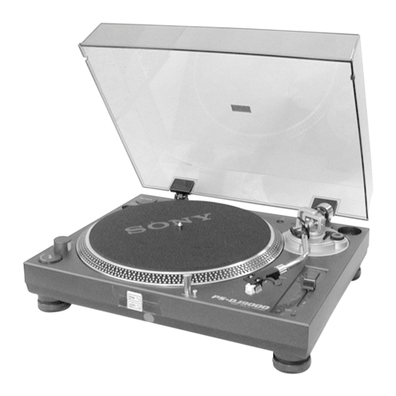
PS-DJ9000
Replacing the Cartridge
The life expectancy of the stylus tip is about 500 hours.
To maintain optimum sound quality and prevent
damage to your records, we recommend replacing the
cartridge before the end of this time duration.
Obtain a replacement cartridge from your Sony dealer.
STEREO TURNTABLE SYSTEM
US Model
AEP Model
UK Model
E Model
1
Advertisement
Table of Contents

Related Manuals for Sony PS-DJ9000 - Stereo Turntable System


Summary of Contents for Sony PS-DJ9000 - Stereo Turntable System
- Page 1 Speeds and 45 rpm Wow and flutter Less than 0.15 % (WRMS) Obtain a replacement cartridge from your Sony dealer. Signal to noise ratio More than 55 dB (DIN-B) Tone Arm Type...
-
Page 2: Table Of Contents
COMPONENTS IDENTIFIED BY MARK 0 OR DOTTED LINE WITH MARK 0 ON THE SCHEMATIC DIAGRAMS AND IN THE PARTS LIST ARE CRITICAL TO SAFE OPERATION. REPLACE THESE COMPONENTS WITH SONY PARTS WHOSE PART NUMBERS AP- PEAR AS SHOWN IN THIS MANUAL OR IN SUPPLEMENTS PUB- LISHED BY SONY. -
Page 3: General
SECTION 1 This section is extracted from instruction manual. GENERAL POWER ON/OFF switch Dust cover Spindle Headshell holder Strobo lamp Counter weight START/STOP button Hinge Slip mat 45 adaptor Platter height adj (adjusting) lever Use this lever to adjust the vertical position of the TARGET LIGHT and release button tonearm (wd). -
Page 5: Diagrams
SECTION 2 DIAGRAMS NOTE FOR PRINTED WIRING BOARD AND SCHEMATIC DIAGRAM Note on Printed Wiring Board: Note on Schematic Diagram: • X : parts extracted from the component side. • All capacitors are in µF unless otherwise noted. pF: µµF •... -
Page 6: Schematic Diagram - Main Section
PS-DJ9000 2-2. SCHEMATIC DIAGRAM – MAIN SECTION – • See Page 8 and 9 for Printed Wiring Boards. (Page 7) (Page 7) (Page 7) SLIDE SW (Page 7) (Page 7) (Page 7) L003, L004, L005, L006: Exchange all the four when even this one diode breaks in either one. -
Page 7: Schematic Diagram - Motor Section
PS-DJ9000 2-3. SCHEMATIC DIAGRAM – MOTOR SECTION – • See Page 10 for Printed Wiring Boards. (Page 6) (Page 6) (Page 6) (Page 6) -
Page 8: Printed Wiring Board - Main Section
PS-DJ9000 2-4. PRINTED WIRING BOARD – MAIN SECTION – • See Page 5 for Circut Boards Location. • See Page 6 for Schematic Diagram. MAIN BOARD RELEASE SW11 TARGET LIGHT • Semiconductor Location Ref. No. Location (Page 9) (Page 10) (Page 10) (Page 9) (Page 9) -
Page 9: Printed Wiring Board - Power Section
PS-DJ9000 2-5. PRINTED WIRING BOARD – POWER SECTION – • See Page 5 for Circut Boards Location. • See Page 6 for Schematic Diagram. RELAY BOARD POWER TRANSFORMER ACIN (Page 10) POWER ON/OFF E, MX POWER TRANSFORMER (Page 10) E,MX AEP, UK POWER TRANSFORMER... -
Page 10: Printed Wiring Board - Motor Section
PS-DJ9000 2-6. PRINTED WIRING BOARD – MOTOR SECTION – • See Page 5 for Circut Boards Location. • See Page 7 for Schematic Diagram. MOTOR BOARD (Page 8) • Semiconductor Location Ref. No. Location (Page 8) (Page 9) (Page 9) -
Page 11: Exploded Views
SECTION 3 EXPLODED VIEW NOTE: • -XX and -X mean standardized parts, so they • Items marked “*” are not stocked since they The components identified by mark 0 or dotted line with mark are seldom required for routine service. Some may have some difference from the original 0 are critical for safety. -
Page 12: Cabinet Section
Ver 1.1 2001.06 3-2. CABINET SECTION supplied supplied supplied with supplied supplied not supplied (POWER board) not supplied (RELAY board) not supplied not supplied (PAUSE/START board) not supplied not supplied (MAIN board) (LED SW board) Ref. No. Part No. Description Remark Ref. -
Page 13: Electrical Parts List
SECTION 4 LED SW MAIN ELECTRICAL PARTS LIST NOTE: • Due to standardization, replacements in the • Items marked “*” are not stocked since they The components identified by mark 0 or dotted line with mark parts list may be different from the parts speci- are seldom required for routine service. - Page 14 MAIN MOTOR Ref. No. Part No. Description Remark Ref. No. Part No. Description Remark 1-247-847-11 CARBON 4.7K 1/4W 1-126-964-11 ELECT 10uF 20.00% 50V 1-247-847-11 CARBON 4.7K 1/4W 1-247-847-11 CARBON 4.7K 1/4W 1-126-768-11 ELECT 2200uF 20.00% 16V 1-247-847-11 CARBON 4.7K 1/4W 1-126-942-11 ELECT 1000uF 20.00% 25V...
- Page 15 PAUSE/START POWER RELAY TONE ARM Ref. No. Part No. Description Remark Ref. No. Part No. Description Remark PAUSE/START BOARD ****************** <SWITCH> SW10 1-570-245-11 SWITCH, MICRO (Bx START STOP) ************************************************************** POWER BOARD ************* < CAPACITOR > 1-164-159-11 CERAMIC 0.1uF 1-164-159-11 CERAMIC 0.1uF 1-126-935-11 ELECT 470uF...
- Page 16 PS-DJ9000 REVISION HISTORY Clicking the version allows you to jump to the revised page. Also, clicking the version at the upper right on the revised page allows you to jump to the next revised page. Ver. Date Description of Revision 2001.06 Correction of specifications and exploded views (74).
Need help?
Do you have a question about the PS-DJ9000 - Stereo Turntable System and is the answer not in the manual?
Questions and answers