Table of Contents
Advertisement
Operator's Manual
CRAFTSMAN
10"
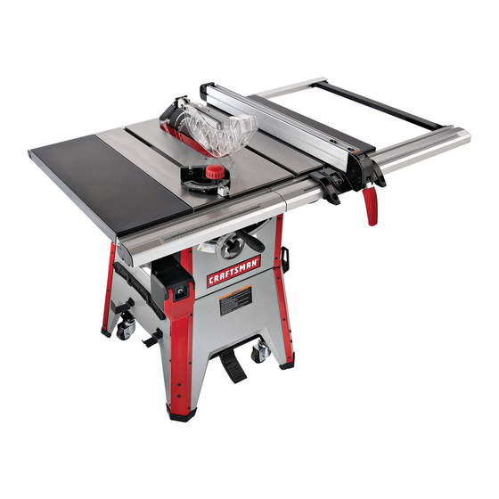
CONTRACTOR TABLE SAW
Model No.
351.218330
CAUTION:
Read and follow all Safety
Rules and Operating
Instructions
before First
Use of this Product. Keep
this Manual with Tool.
Sears, Roebuck and Co., Hoffman Estates, IL 60179 U.S.A.
www, sears.com/craftsman
31105,00 Draft (07/01/09)
Advertisement
Table of Contents

Related Manuals for Craftsman 21833 - Professional Contractor Table Saw


Summary of Contents for Craftsman 21833 - Professional Contractor Table Saw
- Page 1 CONTRACTOR TABLE SAW Model No. 351.218330 CAUTION: Read and follow all Safety Rules and Operating Instructions before First Use of this Product. Keep this Manual with Tool. Sears, Roebuck and Co., Hoffman Estates, IL 60179 U.S.A. www, sears.com/craftsman 31105,00 Draft (07/01/09)
- Page 2 • Keep childrenout of workplace.Make workshopchildproof. TOOL Use padlocks,master switchesor removeswitch keysto if this Craftsman toolfails due to a defect in material or prevent any unintentional u se of powertools. workmanship withinone year from the date of pumhase,call • Keep power cordsfrom comingin contactwith sharp 1-800-4-MY-HOME®TO ARRANGE FOR FREE REPAIR (or...
- Page 3 • Know your tool. Learn the tool's operation, application and • Use extra caution when the guard assembly is removed for specific limitations. resawing, dadoing, or rabbeting--replace guard as soon as that operation is completed. ° Handle workpiece correctly. Press firmly against table. Protect hands from possible injury.
- Page 4 Use extra care when ripping wood with twisted grain or wood that is twisted or bowed--it may rock on table and 4 It pinch saw blade. 5" Long (typ.) Solid Lumber %+" (typ.) J "_ • _,;,,,, IIIIIll}[IlUHIIilIlUlI" ¾,, J Clamp to rip fence or rip fence extension to keep work on the...
- Page 5 • Adjust table inserts flush with table top. Never operate saw M8 x 20 Hex Head Bolt (4) unless proper insert is installed. M8 Lock Washer (20) • Never feed material into the cutting tool from the rear of M8 Flat Washer (20) the saw.
- Page 6 IMPORTANT: Table is coated with a protectant. To ensure ° Place the mobile base assembly onto the cabinet and dust proper fit and operation, remove coating. Coating is easily chute and secure in position with four socket head bolts, removed with mild solvents, such as mineral spirits, and a soft lock washers and flat washers (Fig.
- Page 7 • Use a straight edge to check level and flatness between RAIL ASSEMBLY main and extension tables. Refer to Figure 11, page 22. • After tables are adjusted level and flat, secure the exten- ° Insert two M8 x 28 hex head bolts and two M8 x 25 hex sion tables by tightening the hex nuts completely.
- Page 8 RIP FENCE ASSEMBLY INSTALLATION Refer to Figure 9, page 18. ° Positionrip fence assembly at end of saw. Be certainlock- Locking ing lever (Key No.2) is in UP unlockedposition. ° Place rip fence assembly onto rails,positioning clamp (No. 26) over rear rail and then placingripfence ontofront guide rail.
- Page 9 DESCRIPTION ° Many cover plate screws, water pipes and outlet boxes are The Craftsman 10" Model Number 218330 contractor saw not properly grounded. To ensure proper ground, grounding offers precise cutting performance for all woods up to 3_" means must be tested by a qualified electrician.
- Page 10 Rip Fence Dimensions: BLADE HEIGHT ADJUSTMENT Rip fence ........31¼" Refer to Figure 13, page 26. Rip fence rails (front and rear) ..... 56_" Blade height is controlled by handwheel (Key No. 30) on the front of the saw. Blade capacity maximum ......10"...
- Page 11 SETTING CLAMPING PRESSURE • With the blade at 45 °, tighten the bevel handwheel lock knob to keep the blade from further tilting. Refer to Figure 9, page 18. • Turn the set screw clockwise until it comes in contact with Rip fence has been adjusted at the factory to locksecurely the positive stop.
- Page 12 Remove the motor, test the operation by feeding the workpiece into the blade guard assembly. If the blade guard assembly contacts • Loosen the fastening knob. the blade, place the workpiece under the blade guard assem- ° Hold the knob and pull the locking pin out. bly, not touching the blade, before starting the motor.
- Page 13 PLOUGHING MPORTANT: Your saw is only as accurate and efficient as Performed with rip fence, is grooving with grain long way of blade or cutting tool used. workpiece. Use proper hold downs and feed devices. First, be certain to use the appropriate type of cutting tool for the operation to be performed.
- Page 14 Refer to Figures10, 11 and 13, pages 20, 22 and 26. Congratulations on making a smart purchase. Your new Craftsman ® product is designed and manufactured for WARNING: Turnthe powerswitch"OFF" and unplugthe powercordfrom its powersourcewhen changingthe saw years of dependable operation. But like all products, it blade.
- Page 15 Service Record Craftsman 10" Contractor Table Saw DATE MAINTENANCE PERFORMED REPLACEMENT PARTS REQUIRED...
- Page 16 SYMPTOM POSSIBLE CAUSE(S) CORRECTIVE ACTION Saw stops or will not start 1. Overload tripped I. A[Iow motor to cool and reset by pushing reset switch 2. Saw unplugged from wall or motor Check all plug connections 3. Fuse blown or circuit breaker tripped Replace fuse or reset circuit breaker Cord damaged RepIace cord...
- Page 17 SYMPTOM CORRECTIVE ACTION POSSIBLE CAUSE(S) 1, Dull blade Saw makes unsatisfactory cut 1. Sharpen or replace blade 2. Blade mounted backwards 2. Turn blade around 3. Remove blade and clean 3. Gum or pitch on blade 4. Incorrect blade for cut 4.
- Page 18 Model 351.21 8330 Figure 9 - Replacement Parts Illustration for Rip Fence B_ 8...
- Page 19 PART NO. DESCRIPTION QTY. 09845.00 3CMI-6 E-Ring 31107.00 Locking Handle 31108.00 8 x 50mm Spring Pin 31109.00 Bushing 31110.00 Shaft 31111.00 01923.00 5 x 30mm Spring Pin 31112.00 Adjusting Plate 01203.00 3CMI-5 E-Ring 31113.00 Adjusting Plate 31114.00 Adjusting Screw 31115.00 Base 31116.00 Nylon Screw...
- Page 20 Model 351.218330 Figure 10 - Replacement Parts Illustration for Cabinet...
- Page 21 PART NO, DESCRIPTION QTY. 31125.00 Scale 06346.00 6-I.0 x 12mm Socket Pan Head Screw 31126,00 Front Corner Support 3I I27.00 Front Panel STD870820 8-1.25 x 20ram Socket Head Bolt* STD852008 8ram Lock Washer* STD851008 8mm Flat Washer* 31128.00 Strain Relief 31129.00 Line Cord Hook 09789.00...
- Page 22 Figure 71 Model35!.21833O "Replacement Parts Illustration for Rails...
- Page 23 PART NO. DESCRIPTION QTY. 31138.00 Paddle O6346.OO Switch 17933,00 Circuit Breaker,15A STD863508 5-0.8 x 8ram Pan Head Screw* STD852005 5ram Lock Washer* STD851005 5mm Fiat Washer* 01474,00 5mm Serrated Washer 31128.00 Strain Relief 31139.00 Tapping Screw 31140.00 Switch Plate STD863612 6-1.0 x 12mm Pan Head Screw* STD852006 6mm Lock Washer*...
- Page 24 €_ "0...
- Page 25 • O-DD mmmmm_O ',-- O qqqqq!qq qqq,q !o._- _l" i"o i_"o "o • .-1 LL EmO_ "_ " _-'_ ,.T, o ° ° o ,.o,.0 oO I.L OOOOO 0000_ 0000 ¢- l-l- moNmm COO') "t"" w-"...
- Page 26 Model 351.218330 Figure 13 - Replacement Parts Illustration for Blade Drive 17 16 5_ 5 53_ 41 84 _5 86...
- Page 27 PART NO. DESCRIPTION PART NO. DESCRIPTION QTY. QTY. STD835016 8-1.25 x 16mm Hex Head Bo[t* O7383.00 3CMI-9 Retaining Ring STD852008 8mm Lock Washer* 31205.00 Spacer 16716.00 31206,00 8mm Fiat Washer (W) Bracket STD843620 16-2.0mm Fiber Hex Nut* 31207,0O STD851016 16mm Flat Washer* 31208.00 Spring 31182.00...
- Page 28 Model 351.21 8330 Figure 14 - Replacement Parts Illustration for Blade Guard _''_e'117 :_ '_ \ /is 22 21...
- Page 29 PART NO. DESCRIPTION QTY, 31235.00 6-1.0 x 58mm Hex Head Bolt STD840610 6-1.0mm Hex Nut* STD851006 6mm Flat Washer* 31236.00 Spacer 31237.00 Left Blade Guard 31238.00 Bushing 31239.00 Cover 31240.00 4-0.7 x 15ram Set Screw 06397.00 4-0.7 x 10mm Flat Head Screw 31241.00 Support 3i242.00...
Need help?
Do you have a question about the 21833 - Professional Contractor Table Saw and is the answer not in the manual?
Questions and answers