Table of Contents
Advertisement
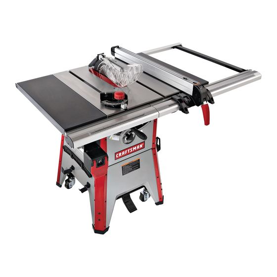
Operator's Manual
10"
CONTRACTOR TABLE SAW
Model No.
351.218330
CAUTION:
Read and follow all Safety
Rules and Operating
Instructions before First
Use of this Product. Keep
this Manual with Tool.
Sears Brands Management Corp., Hoffman Estates, IL 60179 U.S.A.
www.sears.com/craftsman
31105.04 Draft (02/09/10)
• Safety
• Unpacking
• Assembly
• Operation
• Maintenance
• Parts List
• Español
Advertisement
Table of Contents
Troubleshooting

Related Manuals for Craftsman CONTRACTOR 351.21833


Summary of Contents for Craftsman CONTRACTOR 351.21833
- Page 1 Read and follow all Safety Rules and Operating Instructions before First Use of this Product. Keep this Manual with Tool. Sears Brands Management Corp., Hoffman Estates, IL 60179 U.S.A. www.sears.com/craftsman 31105.04 Draft (02/09/10) • Safety • Unpacking • Assembly • Operation •...
-
Page 2: Table Of Contents
WARRANTY ONE-YEAR FULL WARRANTY ON CRAFTSMAN TOOL If this Craftsman tool fails due to a defect in material or workmanship within one year from the date of purchase, call 1-800-4-MY-HOME® TO ARRANGE FOR FREE REPAIR (or replacement if repair proves impossible). - Page 3 STABILITY OF SAW If there is any tendency for the saw to tip over or move during certain cutting operations, such as cutting extremely heavy panels or long heavy boards, the saw should be bolted down.
- Page 4 Figure 1a - Push Sticks and Push Blocks KNOW YOUR CUTTING TOOLS • Dull, gummy, improperly sharpened or set cutting tools can cause material to stick, jam, stall saw, or kickback at oper- ator. Minimize potential injury by proper care and machine maintenance. WARNING: Never attempt to free a stalled saw blade with- out first turning saw OFF.
-
Page 5: Think Safety
Check for shipping damage or missing parts. If any parts are damaged or missing, call 1-800-266-9079 for replacement. The table saw body comes assembled as one unit. Additional parts which need to be fastened to the saw should be located and accounted for before assembling: A Extension Table (2) -
Page 6: Assembly
Do not attempt assembly if parts are missing. Use this manual to order replacement parts. Be certain all parts are clean and free of shipping preserva- tive. Also, completely remove all parts of packing. Saw cabinet should be directly on the floor. SAW INSTALLATION... - Page 7 Below is completed base assembly. Figure 6 ASSEMBLE CASTER SETS Refer to Figures 7-11. ″ Open End Wrenches Tools Required: Two ⁄ • Refer to Figure 7; remove casters (4) and supports (2) from carton. Kick Plate Cam Bracket Figure 7 •...
- Page 8 Install the blade guard storage brackets to the left side panel of the base using four screws, lock washers and flat washers. NOTE: Attach the slotted bracket to the front side of the saw. • Press the four rubber feet to the base legs.
-
Page 9: Install Blade
(see Figure 21). NOTE: Be sure to measure the distance or make the test on the same tooth of the saw blade in both front and rear positions. Flange... -
Page 10: Rail Assembly
(see Figure 22). Loosen the four hex head bolts on the trunnion (see Figure 23) and shift trunnions until a position is found where the saw blade is parallel to the miter guage slots. NOTE: Saw blade should also be centered within its table insert opening. - Page 11 Figure 30 POSITION AND ADJUST RIVING KNIFE Refer to Figure 31. • Riving knife is installed on the saw. Raise the blade com- pletely to access the riving knife. • Loosen the locking knob and raise the riving knife to its highest position.
- Page 12 • The riving knife should also be in line with the saw blade. If adjustment is necessary: 1. Locate the riving knife bracket. 2. Loosen the two socket head cap screws slightly enough to move the bracket, bringing the riving knife in line with the saw blade.
-
Page 13: Assembly
Figure 38 INSTALL RIP FENCE Refer to Figure 39. • Position rip fence assembly at end of saw. Be certain lock- ing lever is in UP unlocked position. • Place rip fence assembly onto rails, positioning clamp over rear rail and then placing rip fence onto front guide rail. -
Page 14: Operation
Make sure unit is off and disconnected from power source before inspecting any wiring. The saw is prewired for use on a 120 volt, 60HZ power supply. The power lines are inserted directly onto the switch. The green ground line must remain securely fastened to the frame to properly protect against electrical shock. -
Page 15: Starting And Stopping The Saw
The saw blade can be set at any angle between 90° and 45°. Blade tilt is controlled by the handwheel (Fig. 44) on the right side of the saw. The indicator (Fig. 45) on front of saw shows the tilt angle of the blade. -
Page 16: Stop Adjustment
Lock handwheel by tightening locking hand knob clock- wise. Tighten only until snug. • The saw is equipped with positive stops at 90° and 45°. These positive stops allow operator to position saw blade at 90° and 45° quickly and accurately. -
Page 17: Rip Fence Adjustment
Figure 48 - Miter Gauge Assembly RIP FENCE ADJUSTMENT The saw's rip fence is precision manufactured, incorporating fine adjustments for accurate cuts. The saw is built to allow the operator to accurately adjust the rip fence without prob- lems in a matter of seconds. -
Page 18: Rip Fence Operation
Make sure blade guard is installed for all “through sawing” operations. Through sawing operations are those opera- tions in which the saw blade cuts completely through the thickness of the wood. Replace guard immediately after completion of resawing, rabbeting and dadoing. -
Page 19: Blade Selection
Therefore, blade guard must be removed. Dado sets have different characteristics than saw blades. As a result, saw must be fitted with special parts that are furnished with saw (Dado Insert, Part No. -
Page 20: Changing The Saw Blade
(C) and saw blade (D). Figure 54 • Place new blade on arbor. Make sure saw blade teeth point down at the front side of saw table. Place flange and nut on arbor and securely snug blade in position. • Replace table insert. -
Page 21: Service Record
Service Record Craftsman 10 Contractor Table Saw ″ DATE MAINTENANCE PERFORMED REPLACEMENT PARTS REQUIRED... -
Page 22: Troubleshooting
Material kicked back from blade TROUBLESHOOTING POSSIBLE CAUSE(S) 1. Overload tripped 2. Saw unplugged from wall or motor 3. Fuse blown or circuit breaker tripped 4. Cord damaged 5. Defective capacitor 1. Stand on uneven floor 2. Damaged saw blade 3. -
Page 23: Troubleshooting
SYMPTOM Saw makes unsatisfactory cut TROUBLESHOOTING (CONTINUED) POSSIBLE CAUSE(S) 1. Dull blade 2. Blade mounted backwards 3. Gum or pitch on blade 4. Incorrect blade for cut 5. Gum or pitch on table CORRECTIVE ACTION 1. Sharpen or replace blade 2. -
Page 24: Parts Illustration And List
Model 351.218330 Figure 55 - Replacement Parts Illustration for Rip Fence... - Page 25 REPLACEMENT PARTS LIST FOR RIP FENCE PART NO. DESCRIPTION 09845.00 3CMI-6 E-Ring 31107.00 Locking Handle 31108.00 8 x 50mm Spring Pin 31109.00 Bushing 31110.00 Shaft 31111.00 01923.00 5 x 30mm Spring Pin 31112.00 Adjusting Plate 01203.00 3CMI-5 E-Ring 31113.00 Adjusting Plate 31114.00 Adjusting Screw 31115.00...
- Page 26 Model 351.218330 Figure 56 - Replacement Parts Illustration for Cabinet 19 20...
-
Page 27: Recommended Accessory
REPLACEMENT PARTS LIST FOR CABINET PART NO. DESCRIPTION 31125.00 Scale 06346.00 6-1.0 x 12mm Socket Pan Head Screw 31126.00 Front Corner Support 31127.00 Front Panel STD870820 8-1.25 x 20mm Socket Head Bolt* STD852008 8mm Lock Washer* STD851008 8mm Flat Washer* 31128.00 Strain Relief 31129.00... - Page 28 Figure 57 - Replacement Parts Illustration for Rails Model 351.218330...
- Page 29 REPLACEMENT PARTS LIST FOR RAILS PART NO. DESCRIPTION 31138.00 Paddle 31558.00 Switch 17933.00 Circuit Breaker,15A STD863508 5-0.8 x 8mm Pan Head Screw* STD852005 5mm Lock Washer* STD851005 5mm Flat Washer* 01474.00 5mm Serrated Washer 31128.00 Strain Relief 31139.00 Tapping Screw 31140.00 Switch Plate STD840610...
- Page 32 Figure 59 - Replacement Parts Illustration for Blade Drive 82 83 84 85 Model 351.218330 53 46 45 44 20 21...
- Page 33 REPLACEMENT PARTS LIST FOR BLADE DRIVE PART NO. DESCRIPTION STD835016 8-1.25 x 16mm Hex Head Bolt* STD852008 8mm Lock Washer* 16716.00 8mm Flat Washer (W) STD843620 16-2.0mm Fiber Hex Nut* STD851016 16mm Flat Washer* 31182.00 Motor STD843217 12-1.75mm Fiber Hex Nut* 04293.00 6 x 6 x 20mm Key 31183.00...
- Page 34 Figure 60 - Replacement Parts Illustration for Blade Guard Model 351.218330...
- Page 35 REPLACEMENT PARTS LIST FOR BLADE GUARD PART NO. DESCRIPTION 6-1.0 x 58mm Hex Head Bolt STD840610 6-1.0mm Hex Nut* STD851006 6mm Flat Washer* Spacer 31237.00 Left Blade Guard Bushing Cover 4-0.7 x 15mm Set Screw 4-0.7 x 10mm Flat Head Screw Support Body 31243.00...
-
Page 36: Español
Get it fixed, at your home or ours! For expert troubleshooting and home solutions advice: For repair – in your home – of all major brand appliances, lawn and garden equipment, or heating and cooling systems, no matter who made it, no matter who sold it! For the replacement parts, accessories and owner’s manuals that you need to do-it-yourself.
Need help?
Do you have a question about the CONTRACTOR 351.21833 and is the answer not in the manual?
Questions and answers
Looking for a blade guard for a Craftsman Contractors table saw model# 351.218330
You can find a blade guard for the Craftsman Contractor Table Saw Model 351.218330 in the replacement parts list. The document includes a "Replacement Parts Illustration for Blade Guard" and a list of key numbers and part numbers for the components. You may need to refer to the parts diagram and order the appropriate part from a supplier that provides Craftsman replacement parts.
This answer is automatically generated