Table of Contents
Advertisement
Operator's Manual
CRSFrSMSN°
10 in. SLiDiNG COMPOUND
MITER SAW WiTH LASER TRAC ®
Model No. 137.212370
CAUTION:
Before using this Miter Saw,
read this manual and follow
all its Safety Rules and
Operating
instructions
•
Safety Instructions
•
installation
•
Operation
•
Maintenance
e
Parts List
Customer
Help Line
For Technical
Support
1-800-843-1682
Sears
Parts
&
Repair
Center
1-800-488-1222
Sears, Roebuck
and Co., Hoffman
Estates,
IL 60179 USA
Visit our Craftsman
website: www.sears.condcraftsman
Part No. 137212370001
Advertisement
Table of Contents

Related Manuals for Craftsman 21237 - 10 in. Sliding Miter Saw


Summary of Contents for Craftsman 21237 - 10 in. Sliding Miter Saw
- Page 1 Maintenance all its Safety Rules and Parts List Operating instructions Sears Parts & Customer Help Line For Technical Support Repair Center 1-800-843-1682 1-800-488-1222 Sears, Roebuck and Co., Hoffman Estates, IL 60179 USA Visit our Craftsman website: www.sears.condcraftsman Part No. 137212370001...
- Page 2 FULL WARRANTY ON CRAFTSMAN TOOL If this Craftsman tool fails due to a defect in material or workmanship within one year from the date of purchase, CALL 1-800-4-MY-HOME(_TO ARRANGE FOR FREE REPAIR (or replacement if repair proves impossible). If this tool is used for commercial or rental purposes, this warranty will apply for only ninety days from the date of purchase.
- Page 3 safety glasses. NOTE: Glasses or goggles not in GENERAL SAFETY iNSTRUCTiONS compliance with ANSI Z87.1 could cause serious Read and understand all the instructions below injury. before using the power tool. These safety 13. WEAR A FACE MASK OR DUST MASK, Sawing instructions are not meant to cover every possible operation produces dust.
- Page 4 I. IMPORTANT: DO NOT USE THIN KERF BLADES. I9. iMPORTANT: ,After completing a cut, release the They can deflect and contact the blade guard and trigger switch and wait for the blade to stop before cause possible in]ury to the operator. returning the saw to the raised position.
- Page 5 4. FUSES may "blow" or circuit breakers may trip ELECTRICAL REQUIREMENTS - cont'd DOUBLE INSULATED frequently if: The power tool is double insulated to provide a double a. MOTOR is overloaded - overloading can occur if thickness of insulation between you and tool's electrical you feed too rapidly or make too many start/stops system.
- Page 6 RECOMMENDED ACCESSORIES Supplied Not supplied ....[AWARNING[ • Use only accessories recommended for this Blade Wrench Adjustable Wrench miter saw. Follow instructions that accompany accessories. Use of improper accessories cause hazards. Hex Key • The use of any cutting tool except 10 inch saw blades which meet the requirements under recommended...
- Page 7 UNPACKING YOUR MITER SAW Place the saw on a secure stationary work surface. Separate all parts from the packing material. Check [A WARNING each one with the illustration below to make certain all items are accounted for before discarding any To avoid injury from unexpected starting or packing material.
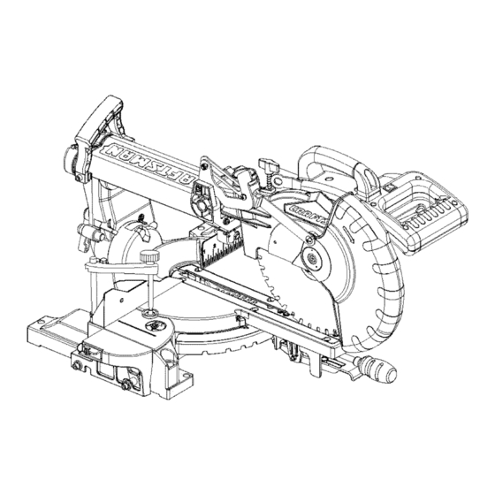
- Page 8 Upper Blade Guard Carrying Handle Laser G uide Carrying Handle LaserON/OFF switch Switch Handle Bevel D etent P in Hold-Down C lamp,..,, ON/OFF Trigger S witch Fence LowerBlade Guard Mounting H oles Blade Table Base LeftExtension T able SlideCarriage Carrying Handle SlideCarriage LockKnob Right E xtension T able Motor...
- Page 9 ARBOR LOCK - Allows the user to keep the blade from WRENCH STORAGE - Convenient storage to prevent rotating while tightening or loosening the arbor locking misplacing the blade wrench. bolt during blade replacement or removal. WOODWORKING TERMS BASE - Supports the table, holds accessories and allows for workbench or leg set mounting.
- Page 10 CUTTING HEAD (FIG. C) Estimated Assembly Time: 5 - 10 minutes Raising [,AWAR"I"G I 1. Push down slightly on the switch handle (I). Pull out the stop latch knob (2). To avoid injury, do not connect this miter saw to the 3.
- Page 11 iNSTALLiNG THE HOLD-DOWN CLAMP 1. To remove, loosen and remove the six screws (1) (FIG. E and E-l) on the table insert (2) with a Phillips screwdriver and remove the insert. I. Place the hold=down clamp assembly (1) in one of the mounting holes (2).
- Page 12 Mounting instructions 4. Rotate the cover plate (3) towards the rear of the tool 1. For stationary use, place the saw in the desired to expose the arbor bolt (4). 5. Place the blade wrench over the arbor bolt. location, directly on a workbench where there is room for handling and proper support of the workpiece.
- Page 13 Installing Blade (Fig. H, I, J) 1 .To turn laser on, press on/off rocker switch (1) to Unplug the miter saw before changing/installing "ON" position: blade. 2.To turn off laser, press on/off rocker switch (1) to I. Install a I 0 in. blade with a 5/8 in. arbor, making "OFF"...
- Page 14 BEVEL STOP ADJUSTMENT Fig. M [4 WARNNNG To avoid injury from an accidental start, make sure the switch is in the OFF position and the plug is not connected to the power source outlet. 90 ° (0 °) Bevel adjustment (Fig.
- Page 15 MITER ANGLE ADJUSTMENT (FIG. O) Fig. P The sliding compound miter saw scale can be easily read, showing miter angles from 0 ° to 45 ° to the left, and 0 _'to 45 ° to the right. The miter saw table has nine of the most common angle setttings with positive stops at 0 _',15 °, 22.5 °, 31.6 °, and 45 °.
- Page 16 SAFETY iNSTRUCTiONS FOR BASIC SAW missing, damaged or broken, or any electrical parts OPERATIONS do not work, turn off the saw and unplug it. • Replace bent, damaged, missing or defective parts BEFORE USING THE MITER SAW before using the saw again. [A WARNING •...
- Page 17 PLAN YOUR WORK • Keep the out piece free to move sideways after it is Use the right tool. Do not force a tool or attachment cut off. Otherwise, it could get wedged against the to do a job it was not designed to do. Use a different blade and thrown violently.
- Page 18 BASIC SAW OPERATIONS BODY AND HAND POSITION (FIG. R) (A WARNINO [AWARNING Never place hands near the cutting area. Proper For your convenience, your saw has a blade brake. positioning of your body and hands when The brake is not a safety device. Never rely on it to operating the miter saw will make cutting easier and replace the proper use of the guard on your saw.
- Page 19 SLIDING CARRIAGE SYSTEM (FIG. 1") When the table is in the desired position, as shown on the miter scale (3), release the positive stop [A WARNING locking lever and tighten the miter handle. The table To reduce the risk of injury, return carriage to the is now locked at the desired angle.
- Page 20 NOTE: T hesawcomes witha 33.9 ° crownmolding SLIDE CUTTING WIDE BOARDS UP TO 12 in. WIDE stop. (FIG. Y) IAWA"Ni"G I 33.9 ° BEVEL STOP FOR CROWN MOLDING (FIG. W) I. Push the bevel detent stop pin (2) in toward the front To avoid injury: of the machine.
- Page 21 AUXILIARY WOOD FENCE (FIG. CC) CUTTING BOWED MATERIAL (FIG. Z) When making multiple or repetitive cuts that result in A bowed workpiece must be positioned against the fence and secured with a cramping devise before cutting cut-off pieces of one inch or less, it is possible for the saw blade to catch the out=off piece and throw it out of as shown.
- Page 22 CUTTING BASE MOLDING (FIG. DD) Fig. EE Base moldings and many other moldings can be cut on a compound miter saw. The setup of the saw depends on molding characteristics and applications, as shown. Perform practice cuts on scrap material. To achieve best results: I.
- Page 23 CROWN MOLDING CHART Compound Miter Saw Miter and Bevel Angle Settings Wall to Crown Molding Angle 52/38 ° C_own Molding 45/48 ° Crown M oldinc:} 52/38 ° Crown M )[ding 45/45" CF@/S n Molding Angle Between Miter Setting Bevei Setting Miter Se_ting Bevel Setting Angle Between...
- Page 24 [AWAR"m"G ] MAINTENANCE = Do not use solvents on the guard. They could DANGER make the plastic "cloudy" and brittle. Never put lubricants on the blade while it is • When cleaning the lower guard, unplug the spinning. saw from the power source receptacle to avoid [A WAR..
- Page 25 WARNING To avoid injury from accidental starting, always turn switch OFF and unplug the tool before moving, replacing the blade or making adjustments. TROU BLESHOOTING GUIDE - MOTOR PROBLEM PROBLEM CAUSE SUGGESTED CORRECTIVE ACTION Brake does not I. Motor brushes not sealed or lightly Inspect/clean/replace brushes.
- Page 26 MODEL.O 137.212370 IA WARNING When servicing use only CRAFTSMAN replacement parts. Use of any other parts many create a HAZARD or cause product damage. Any attempt to repair or replace electrical parts on this Miter Saw may create a HAZARD unless repair...
- Page 27 10 IN. SLIDING COMPOUND MITER SAW MODEL NO. 137.212370 SCHEMATIC FOR SAW OJXT, 2DXA 2 DUY OJBO @2ESH _DX5 _DXO OCM3 {]TWD EJL3 _DWL @2C37...
- Page 28 10 IN. SLiDiNG COMPOUND MITER SAW MODEL NO. 137.212370 PARTS LIST AND SCHEMATIC FOR MOTOR Size I.D No. Description OHVS BALL BEARING 6201ZLU OHVU BALi= BEARING 6200Z OHX9 NEEDLE BEAR NG OJX2 HEX. SOC SETSCREW M5'0.8-6 0K43 CR. RE. PAN HD. SCREW & WASHER M5'0.8 0K44 CR, RE.
- Page 30 Your Home For repair - in your home - of all major brand appliances, lawn and garden equipment, or heating and cooling systems, no matter who made it, no matter who sold it! For the replacement parts, accessories owner's manuals that you need to do-it-yourself. For Sears professional installation of home appliances and items like garage door openers and water heaters.
Need help?
Do you have a question about the 21237 - 10 in. Sliding Miter Saw and is the answer not in the manual?
Questions and answers