Table of Contents
Advertisement
Operator's lVlanual
ERRFrSNRN°
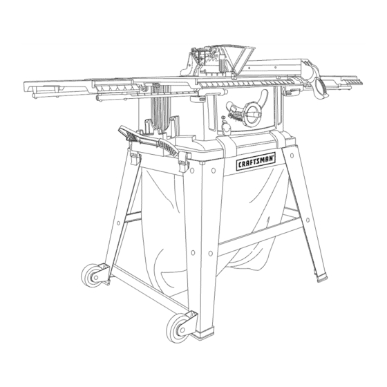
10-in. TABLE SAW WiTH LEG SET
Model No. 137.218070
C
us
CAUTION:
Before using this Table Saw,
read this manual and follow
all its Safety Rules and
Operating
Instructions
®
Safety Instructions
®
Installation
®
Operation
®
Maintenance
®
Parts List
Customer
Help
Line
For Technical
Support
1-800-843-1682
Sears
Parts
&
Repair
Center
1-800-488-1222
Sears, Roebuck
and Co., Hoffman Estates, IL 60179 USA
Visit our Craftsman
website:
www.sears.comlcraftsman
Part No. 137218070001
Printed in Taiwan
Advertisement
Table of Contents

Related Manuals for Craftsman 21807 - 10 in. Table Saw


Summary of Contents for Craftsman 21807 - 10 in. Table Saw
- Page 1 Safety Rules and ® Parts List Operating Instructions Sears Parts & Customer Help Line For Technical Support Repair Center 1-800-843-1682 1-800-488-1222 Sears, Roebuck and Co., Hoffman Estates, IL 60179 USA Visit our Craftsman website: www.sears.comlcraftsman Part No. 137218070001 Printed in Taiwan...
-
Page 2: Table Of Contents
Parts List ....................CRAFTSMAN ONE YEAR FULL WARRANTY If this Craftsman tool fails due to a defect in material or workmanship within one year from the date of purchase, call 1-800-4-MY-HOME®to arrange for free repair (or replacement if repair proves impossible). - Page 3 MOTOR Type ................Universal Amperes ............... 15 Amp Voltage ................ 120V AC Hz ................60Hz RPM (no load) ............5000 RPM (No load) Overload Protection ............ BLADE SIZE Diameter ..............10 in. Arbor size ..............5/8 in. Rip fence ..............Miter gauge ..............
-
Page 4: Symbols
WARNING iCONS Your power tool and its Operator's Manual may contain "WARNING iCONS" (a picture symbol intended to alert you to, and/or instruct you how to avoid, a potentially hazardous condition). Understanding and heeding these symbols will help you operate your tool better and safer. Shown below are some of the symbols you may see. -
Page 5: Power Tool Safety
GENERAL SAFETY iNSTRUCTiONS 6. KEEP CHILDREN AWAY. All BEFORE USING THiS POWER TOOL visitors and bystanders should be kept a safe distance from work area. Safety is a combination of common sense, staying alert and knowing how 7. MAKE WORKSHOP CHILD PROOF to use your power tool. - Page 6 12.ALWAYS W EAR EYE 17.USE RECOMMENDED ACCESSORIES. Consult tool can throw foreign this Operator's Manual for PROTECTION. Any power recommended accessories. The use objects into the eyes and could cause permanent of improper accessories may cause eye damage. ALWAYS wear Safety risk of injury to yourself or others.
- Page 7 22.MAINTAIN T OOLS WITH CARE. Keep toolssharp andcleanforbest andsafestperformance. Follow instructions forlubricating a nd changing accessories. 23.WARNING: Dustgenerated f rom certainmaterials c anbehazardous toyourhealth. A lways operate saw inwell-ventilated areaandprovide forproper dustremoval. 24"[,A DANGER People with electronic devices, such as pacemakers, should consult their physician(s) before using this product.
- Page 8 1.ALWAYS USESAWBLADE 6. NEVER REACH behind or over the GUARD, rivingknifeandanti- cutting tool for any reason. kickback p awls for every through- sawing operation. Through-sawing 7. REMOVE the rip fence when operations are those in which the crosscutti ng. blade cuts completely through the workpiece when ripping or 8.
- Page 9 slipcouldcause yourhand to move 21 .USE ONLY saw blades recom- intothesawblade. mended with warning that the riving knife shall not be thicker than the 15.NEVER USESOLVENTS t o width of the groove cut by the saw cleanplasticparts. S olvents c ould blade and not thinner than the body possibly d issolve or otherwise of the saw blade.
- Page 10 GROUNDING iNSTRUCTiONS GUiDELiNES FOR EXTENSION CORDS IN THE EVENT OF A MALFUNCTION OR BREAKDOWN, grounding provides USE THE PROPER EXTENSION a path of least resistance for electric CORD. Make sure your extension cord currents and reduces the risk of electric is in good condition.
- Page 11 Fig.1 shows a three-pronged electrical CAUTION plugandreceptacle t hathasa This tool must be grounded while grounding c onductor. Ifa properly in use to protect the operator from grounded receptacle i snotavailable, electric shock. anadapter ( Fig.2)canbeusedto temporarily connect t hisplugtoa O"...
- Page 12 ACCESSORIES WARNING Blade wrench Flat bladed Visit your Sears Hardware screwdriver Department or see the Craftsman Power and Hand Tools Catalog to purchase recommended #2 Phillips screwdriver accessories for this power tool. Blade wrench WARNING] !!!!!!!!!!! To avoid the risk of personal...
- Page 13 cord, or turn the switch ON until Separate all parts from packing the missing or damaged part is materials. Check each part with the obtained and is installed correctly. illustration on the next page and the "Table of Loose Parts" to make certain Call 1=800-843-1682 for missing all items are accounted for, before damaged...
- Page 14 UNPACKING YOUR TABLE...
- Page 15 Blade guard Miter gauge _ip fence Left extension table wing Overload reset switch locking lever elevation and Miter gauge-rip tilting handwheet fence-push stick storac ON/OFF switch with safety key Lock Footpad Dustbag switch Riving knife Blade Table insert pawls Hand Rear table extension wing Right extension wrap...
- Page 16 ANTI-KICKBACK PAWLS - Prevents the workpiece from twisting during the the workpiece from being kicked cutting operation. upward or back toward the front of the table saw by the spinning blade. GUM - A sticky sap from wood products. ARBOR - The shaft on which the blade or dado is mounted.
- Page 17 FEATHERBOARD - Whenripping TABLE INSERT - Insert that is a workpiece o nyourtablesaw,this removed from the table to install/ keeps itfirmlyandsafelyagainst the remove blades. It is also removed for ripfence.It alsohelpsprevent chatter, dado cutting. When dado cutting, a gouging, a nddangerous k ickback. dado insert plate must be used.
- Page 18 ASSEMBLE STAND (FIG. A, B, C) 5. Assemble the other upper supports 1. Unpack all parts and group by type in exactly the same manner. and size. Refer to the parts list for 6. Attach one bottom support (5) to the correct quantities.
- Page 19 Fig.D Fig. F Repeat steps 1-4 for left rear leg (17) ASSEMBLE TABLE SAW TO STAND and roller wheel assembly. USING LEVER LOCK (FIG. G) NOTE: The roller wheel assemblies 1. Attach the locking lever assembly (18) and bottom support bracket (18) to the top of the leg (2).
- Page 20 MOUNTING BASE TO STAND USING 5. Mark an 11 in. square (2) centered BOLTS (FIG. H) between the four mounting holes (1). You can also attach the saw base to the 6. Cut out and remove the square. stand using standard bolts. 7.
- Page 21 RiP FENCE (FIG. K) Fig. L 1. Lift upward on the rip fence handle (1) so the rear holding clamp (2) is fully extended. 2. Place the rip fence on the saw table, and attach the set plate (3) under the fence handle (1) to the rail first.
- Page 22 6.Thread thearbornut(2)ontothe REMOVING THE BLADE (FIG. N, O) arbor, m aking suretheflatsideof the nutis against t heblade, t hen I,A WARNING hand-tighten. (Fig.N) To avoid injury from an accidental 7.Totighten thearbornut(2),place start, make sure the switch is in theopen-end w rench (5)ontheflats the OFF position and the plug is ofthesawarborto keepthearbor disconnected...
- Page 23 Installing the riving knife assembly Aligning the riving knife (Fig. Q) (Fig. P, P=I) I,A WARNING 1. Remove the table insert 2. With the blade elevation handwheel o To avoid injury from an accidental (1), raise the blade arbor to the start, make sure the switch is in maximum height.
- Page 24 NOTE: o When installing the blade guard, o Thewashers (1/4"1/2-3/32) (5)are cover the blade teeth with a piece notincluded w iththistablesaw.It of folded cardboard to protect mustbepurchased s eparately. yourself from possible injury. o Riving knifethickness i s 0.09in. o Never operate this machine o Themaximum radial d istance without the blade guard in place between therivingknifeandthe...
- Page 25 2. Loosen the blade lock handle do not Take the blade guard assembly and locate the black sliding locking knob pull on handle just turn and move the handwheel to 90 ° on the bevel scale. (4) on the back of assembly. (Fig. T) 3.
-
Page 26: Carton Contents
2. Unlock bothfrontandrearcam Snap two black plastic stops (3) locking levers (1)ontherighthand over the two rear table extension sideofthesawbasebyflipping the tubes (2). Make sure the locating leverover. pin in the black plastic stops fits into 3. Insert t hetableextension mounting the matching hole in the extension tubes(2)intothetwomatching tube. - Page 27 ADJUSTING THE REAR TABLE the left side of the body shell. The EXTENSION (FIG. X) bracket will snap into place. 1. The rear table extension (1) should be positioned as close as possible Fig. Z to the rear of the table when ripping short material.
- Page 28 MOVE THE TABLE SAW (FIG. CC) 4. if adjustment is needed to make the 1. Slide the table extension toward fence parallel to the groove, do the the table until it rests against the following: saw table and tighten the two cam- o Loosen the two bolts (3) and lift locking levers.
- Page 29 RiP FENCE iNDiCATOR 3. To change angles on the miter gauge, ADJUSTMENT (FIG. EE) loosen the lock handle (1) and rotate 1. The rip fence indicator (6) points to the miter body to the desired angle the measurement scale. The scale as indicated by the scale.
- Page 30 ADJUSTING THE 90 ° AND 45 ° 45 ° Stop POSiTiVE STOPS (FIG. HH, ii) 1. Disconnect the saw from the power source. Your saw has positive stops that will 2. Raise the blade to the maximum quickly position the saw blade at 90 ° elevation.
- Page 31 BLADE PARALLEL TO THE MITER If the ruler touches the marked tooth GAUGE GROOVE (FIG. JJ, KK) at the front and rear position, no adjustment is needed at this time. WARNING] If not or the base of the rule is no This adjustment was made at the longer parallel with the edge of factory,...
- Page 32 If the blade is partial to left side: o Do not perform any adjustments that are intended to increase the 1. Turn the right adjustment screw (3) power of the laser. counterclockwise and adjust the left o When using the laser line, do not side adjustment screw (2) clockwise.
- Page 33 LASER RADIATION. 3. If the laser line is not flush, loosen Do not stare into the beam or view it the two set screws (1) using a small flat bladed screwdriver that is not directly using optical instruments. Maximum output: < 1 mW provided, but do not remove them.
- Page 34 BASIC SAW OPERATIONS 2. To turn the saw OFF, move the switch downward. RAISE THE BLADE (FIG. MM) 3. To lock the switch in the OFF position, To raise or lower the blade, turn the grasp the end (or yellow part) of the blade elevation handwheel (1) to the safety switch key (1), and pull it out.
- Page 35 USING THE TABLE EXTENSION grain of the workpiece. (It is not safe to (FIG. OO, PP) rip or crosscut by freehand). Ripping If the table extension is not parallel requires the use of the rip fence, and with the table, remove the bolts (1) and crosscutting requires the miter gauge.
- Page 36 The workpiece must have a WARNING i straight edge against the fence When width or rip narrower than and must not be warped, twisted, 2 in. the push stick cannot be or bowed when ripping. used because the blade guard will interfere.
- Page 37 BEVEL RIPPING MAKE A FEATHERBOARD (FIG. SS) This cut is the same as ripping except Select a solid piece of lumber the blade bevel angle is set to an angle approximately 3/4 in thick, 4 in wide and other than "0°''. 18 in long.
- Page 38 AUXILIARY FENCE (FIG. UU) MAKE A PUSH BLOCK (FIG. VV) Making the base: Making the base: o Start with a piece of 3/8 in. plywood o Start with a 3/8 in. plywood at least at least 5-1/2 in. wide or wider and 5-1/2 in.
- Page 39 I WARNING CROSSCUTTING (FIG. WW) WARNING] Always position the larger surface of the workpiece on the table To prevent serious injury: when crosscutting and/or bevel o Do not allow familiarity or frequent crosscutting to avoid instability. use of your table saw to cause careless mistakes.
- Page 40 BEVEL CROSSCUTTING (FIG.YY) groove because the bevel angle may 0°-45° BLADE BEVEL & 90° MITER cause the blade guard to interfere ANGLE Thiscuttingoperation with the cut if used on the left side is the same as crosscutting except the blade groove.
- Page 41 USING THE WOOD FACING ON THE To avoid the risk of personal RiP FENCE (FIG. bb) injury. Always use push block, When performing some special cutting auxiliary fence and featherboard operations, you can add a wood facing when making non-through cut.
- Page 42 DADO CUTS (FIG. dd, ee) chippers as shown in the dado set's instruction manual. Blade/chippers 1,,_, WARNING] must not exceed 1/2 in. total in width. o Only Stackable dado blades can be used on this saw. o DO NOT use Adjustable or Wobble Fig.
-
Page 43: Maintenance
MAINTAINING YOUR TABLE SAW 1. With the saw disconnected from the power source, turn the saw upside GENERAL MAINTENANCE down and pull up and push down on the motor unit. {,,A WARNING] 2. Observe any movement of the motor mounting mechanism. For your own safety, turn the switch 3. - Page 44 NOTE: I f excessive l ooseness 6. Remove the black plastic cap (2) isobserved inanypartofthe from the side of the motor (3). bladeraising mechanism ortilting 7. Carefully remove the spring-loaded mechanism, takethecomplete unitto a cap, and then pull out the brush and Service Center.
- Page 45 i,A WARNING To avoid injury from accidental starting, always turn switch OFF and unplug the tool before moving, replacing the blade or making adjustments. PROBLEM POSSIBLE CAUSES CORRECTIVE ACTION Saw will not 1. Saw is not plugged in. 1. Plug in saw. start.
- Page 46 1,_ WARNING To avoid injury from accidental starting, always turn switch OFF and unplug the tool before moving, replacing the blade or making adjustments. Material kicked 1. Rip fence out of adjustment. 1. Align rip fence with miter back from blade. 2.
- Page 47 PUSH STICK CONSTRUCTION Use good quality plywood or solid wood ® Use 1/2 in. or 3/4 in. material ® Push stick MUST be thinner than the width of ® material being cut Drill Hole For Hanging Notch To Prevent Hand From Slipping /"...
- Page 48 10 in. TABLE SAW MODEL NO. 137.218070 WARNING When servicing use only CRAFTSMAN replacement parts. Use of any other parts many create a HAZARD or cause product damage. Any attempt to repair or replace electrical parts on this Table Saw may create a HAZARD unless repair is done by a qualified service technician.
- Page 49 > > 2TB9 > 10K54 OKCX4 02J A F _0KBQ 2SUS...
- Page 50 10 in. TABLE SAW MODEL NO. 137.218070 PARTS LiST FOR SAW SCHEMATIC Size I.D. Description Size I.D. Description 0901 BUSH OKSM STRAIN RELIEF 08VH CORD CLAMP OKTH STRAIN RELIEF 08VN POINTER BRACKET OKUX TERMINAL 090Q PLUNGER HOUSING OKWU LEAD WIRE ASS'Y 09JK WRENCH OLSL...
- Page 51 OJ6K OK J7 OBPA "_ _O_o_v_ 09018D_OJ OJAF 2TDL 26E8 29R6 )J4F 2RVR4 2815 08VH/_ OKA4_ OB3R _0KUX 0KTH "q 0KWU 2TDS_...
- Page 52 10 in. TABLE SAW MODEL NO, 137.218070 PARTS LiST FOR MOTOR I.D. Description Size OHX9 NEEDLE BEARLNG OJX3 HEX. SOC. SETSCREW M5"0.8-8 OK3Y CR. RE. PAN HD. SCREW & WASHER M5"0.8-50 OKTA STRAIN RELIEF OQM2 BRUSH HOLDER ASS'Y @27"26,5 OQQT BRUSH ASS'Y OQR0 BRUSH COVER...
- Page 53 10 in. TABLE SAW MODEL NO. 137.218070 PARTS LiST FOR STAND I.D, Description Size I.D. Description Size 2SB2 PLUNGER HOUSING 0J4F FLAT WASHER @8_16-2.5 0JPS HEX. HD. BOLT M8_1.25-45 2SB3 CLAMP HANDLE 0KJ7 CAP HD. SQ. FLECK BOLT M8_1.25-16 2SBX HANDLE 0KHX CAP HD.
- Page 56 Your Home For expert troubleshooting and home solutions advice: www.managemyhome.com For repair - in your home - of all major brand appliances, lawn and garden equipment, or heating and cooling systems, no matter who made it, no matter who sold it! For the replacement parts, accessories owner's manuals that you need to do-it-yourself.
Need help?
Do you have a question about the 21807 - 10 in. Table Saw and is the answer not in the manual?
Questions and answers