Hunter ST Series, ST-1700-V Manual
- Owner's manual (12 pages) ,
- Owner's manual (9 pages) ,
- Owner's manual (12 pages)
Advertisement
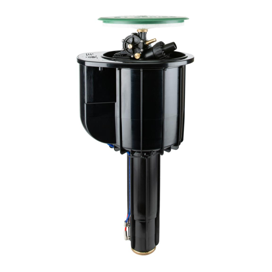
Overview
Hunter's synthetic turf rotors are designed to cool, clean, and flush synthetic sports fields. The long-range ST-1700-V Synthetic Turf Rotor offers high-performance irrigation from the field perimeter while integrating Valve-in-Head (VIH) capabilities and a Total-Top-Service (TTS) design to simplify installation and maintenance. With the same heavy-duty internal gear drive as the proven ST-1600-HS-B Synthetic Turf Rotor, the ST-1700-V provides years of reliable operation.
Valve-in-Head
The Valve-in-Head design integrates the control valve, solenoid, and manual On-Off-Auto selector within the rotor's heavy-duty, impact-resistant case. The convenient and compact design is appreciated by installers and end users.
Total-Top-Serviceability
With Total-Top-Serviceability, every serviceable component can be accessed from the surface without cutting into the synthetic turf. The spacious flange compartment can accommodate fullsized waterproof splice connectors, and the compartment can hold a decoder for two-wire control system applications.
Key Benefits
- Heavy-duty internal gear drive and stainless steel pop-up riser provide years of reliable operation
- Long-range performance flexibility up to 157' with five nozzle choices
- Full-circle and adjustable arc in one model from 40° to 360°
- Adjustable speed of rotation using the adjustment knob to set the speed to your requirements

Water may contain foreign objects, such as sand, rocks, and other impurities, which can damage the rotor. To avoid these problems, it may be necessary to install a filter.
After Installation
Troubleshooting non-rotation:
- Check for a plugged secondary nozzle.
- Check for a blocked propeller in the turbine assembly.
Troubleshooting non-operation after connecting to a decoder system:
- Check for proper wire connections.
- Switch the two solenoid wires.

- Do not perform any adjustments or controls during operation.
- Stand clear of the action area of the rotor and the water jet.
- Ensure the water jet is not directed toward persons, animals, power lines, roads, or other objects.
Troubleshooting
Find more helpful information about your product, including installation tips, and more.

Product Details

Product Dimensions
- Overall height: 263/4"
- Pop-up height: 5"
- Exposed diameter: 13" x 151/4"
- Inlet size: 2" NPT
Operating Specifications
- Radius: 105' to 157'
- Flow: 92.4 to 259 GPM
- Operating pressure range: 60 to 120 PSI
- Speed of rotation: 80 seconds at 120 PSI

Replacement Parts


| ITEM | DESCRIPTION | CATALOG NO. | |
| 1 | Primary Nozzle Retainer | 502402SP | |
| 2 | Primary Nozzle Kit | #16 | 784800SP |
| #18 | 784801SP | ||
| #20 | 784802SP | ||
| #22 | 784803SP | ||
| #24 | 784804SP | ||
| 3 | Secondary Nozzle Kit | Female-threaded nozzle with elbow | 10005900SP |
| Male-threaded nozzle | 10006100SP | ||
| 4 | Speed Control Knob | 510101SP | |
| 5 | Gearbox Cover | 502455 | |
| 6 | Turbine Assembly Kit | 10006200SP | |
| 7 | Reversing Kit | 510164SP | |
| 8 | Turret Inlet Kit | 510167SP | |
| 9 | Threaded Rotor Inlet | 893600SP | |
| 10 | Arc Rings (2) | 205617SP | |
| 11 | Gear Drive Assembly | 881900SP | |
| 12 | Rotor Cover Kit | 204205SP | |
| 13 | Upper Body Kit | 10006300SP | |
| 14 | Solenoid Actuator Kit | 10006400SP | |
| 15 | Actuator Cover | 10006500SP | |
| 16 | Riser Assembly | 502436SP | |
| 17 | Rubber Boot | 502423 | |
| 18 | Snap Ring | 10006600SP | |
| 19 | Valve-in-Head with Stainless Steel Ring | 10006700SP | |
| 20 | Gear Drive Insertion/Removal Tool | 517600SP | |
| 21 | Valve-in-Head Insertion/Removal Tool | 10000100SP | |
| 22 | Snap Ring Removal Tool | 251000SP | |
Servicing and Maintenance
- Replacing the cover and rotor
- Remove the center plug with a flatblade screwdriver and unscrew the nut underneath. The lid will lift off.
![]()
- Use the gear drive insertion/removal tool to unscrew the rotor from the piston.
![]()
- The tool will grab onto the screws underneath the rotor.
![]()
- Remove the center plug with a flatblade screwdriver and unscrew the nut underneath. The lid will lift off.
- Replacing the propeller
- Remove the eight screws on the turbine housing (six large, two small). The propeller will pull out of the housing.
![]()
- Remove the eight screws on the turbine housing (six large, two small). The propeller will pull out of the housing.
- Accessing the solenoid
- Remove the three screws from the top of the solenoid housing. The housing lifts off.
![]()
- Remove the three screws from the top of the solenoid housing. The housing lifts off.
- Part-circle and 360° operation
![]()
- Lift up the cover. Set the arc adjustment rings to the desired arc (this can be done by hand).
- Remove both adjustment rings completely to allow full 360° operation.
- Accessing the valve-in-head
Remove the rotor (see Step A) and boot. Unscrew the six Allen bolts on the piston flange. Remove the piston.- Remove the snap ring with the Snap Ring Removal Tool.
![]()
- Remove the valve and stainless steel ring with the valve insertion/ removal tool.
![]()
- Remove the snap ring with the Snap Ring Removal Tool.


Installation Guide

SOLENOID COMPARTMENT DETAIL
- Discharge port
- Solenoid*
- Water line to filter (RED)
- Water line to Valve-in-Head (BLUE)
*If connecting to a two-wire system, there is potential for miswiring the solenoid. Should your solenoid not fire during system startup, your first troubleshooting measure should be to swap the two solenoid wires.
INSTALLATION DETAIL
- ST-1700-V Synthetic Turf Rotor
- Synthetic turf per plans
- Decoder and Solenoid with waterproof connectors within compartment
- Coarse rock for drainage
- Solenoid wire connection
- Hunter HSJ-5-3-8-3-12 Swing Joint: 3" male NPT inlet with 2" male NPT outlet
- Mainline and fittings
- Compacted soil where applicable
- Aggregate base per plan
- Infill Barrier System ST-IBS-1700
- Suggested isolation valve
Field Layouts

International soccer field with Nozzle 24 installed, operating at 90 PSI

Field hockey field with Nozzle 20 installed, operating at 100 PSI

| ST-1700-V PERFORMANCE CHART | |||||
| Nozzle | Pressure PSI | Radius ft | Flow GPM | Precipitation in/hr* | |
 |  | ||||
| 16 | 60 | 105 | 92.4 | 1.61 | 1.86 |
| 70 | 114 | 100.0 | 1.48 | 1.71 | |
| 90 | 120 | 114.0 | 1.52 | 1.76 | |
| 100 | 126 | 124.0 | 1.50 | 1.74 | |
| 115 | 130 | 134.1 | 1.53 | 1.76 | |
| 18 | 60 | 111 | 107.0 | 1.67 | 1.93 |
| 70 | 119 | 115.0 | 1.56 | 1.81 | |
| 90 | 126 | 127.0 | 1.54 | 1.78 | |
| 100 | 131 | 137.0 | 1.54 | 1.77 | |
| 115 | 137 | 148.9 | 1.53 | 1.76 | |
| 20 | 60 | 114 | 134.1 | 1.99 | 2.29 |
| 70 | 127 | 151.0 | 1.80 | 2.08 | |
| 90 | 135 | 164.0 | 1.73 | 2.00 | |
| 100 | 141 | 180.0 | 1.74 | 2.01 | |
| 115 | 146 | 193.7 | 1.75 | 2.02 | |
| 22 | 60 | 115 | 153.7 | 2.24 | 2.58 |
| 70 | 127 | 174.0 | 2.08 | 2.40 | |
| 90 | 141 | 189.0 | 1.83 | 2.11 | |
| 100 | 149 | 206.0 | 1.79 | 2.06 | |
| 115 | 154 | 222.2 | 1.80 | 2.08 | |
| 24 | 60 | 121 | 177.2 | 2.33 | 2.69 |
| 70 | 132 | 201.0 | 2.22 | 2.56 | |
| 90 | 144 | 222.0 | 2.06 | 2.38 | |
| 100 | 154 | 240.0 | 1.95 | 2.25 | |
| 115 | 157 | 259.0 | 2.02 | 2.34 | |
* Precipitation rates are shown with head-to-head coverage.
Notes:
All radius measurements are taken at standard rotation speeds.
| ST-1700-V WITH SHORT-RADIUS NOZZLES (P/N 959900) | |||||
| Nozzle | Pressure PSI | Radius ft | Flow GPM | Precipitation in/hr* | |
| | ||||
| 16 | 60 | 70 | 26.3 | 1.03 | 1.19 |
| 70 | 72 | 28.5 | 1.06 | 1.22 | |
| 90 | 74 | 31.3 | 1.10 | 1.27 | |
| 100 | 76 | 33.2 | 1.11 | 1.28 | |
| 10 | 60 | 81 | 37.8 | 1.11 | 1.28 |
| 70 | 84 | 42.5 | 1.16 | 1.34 | |
| 90 | 86 | 47.1 | 1.23 | 1.42 | |
| 100 | 88 | 49.5 | 1.23 | 1.42 | |
| 12 | 60 | 92 | 53.9 | 1.23 | 1.42 |
| 70 | 94 | 60.5 | 1.32 | 1.52 | |
| 90 | 96 | 65.7 | 1.37 | 1.58 | |
| 100 | 98 | 69.0 | 1.38 | 1.60 | |
| 14 | 60 | 103 | 69.3 | 1.26 | 1.45 |
| 70 | 105 | 78.2 | 1.37 | 1.58 | |
| 90 | 108 | 85.5 | 1.41 | 1.63 | |
| 100 | 110 | 89.4 | 1.42 | 1.64 | |
* Precipitation rates are shown with head-to-head coverage.
Notes:
All radius measurements are taken at standard rotation speeds.
HUNTER INDUSTRIES
1940 Diamond Street, San Marcos, California 92078 USA
hunterirrigation.com
Documents / Resources
References
Download manual
Here you can download full pdf version of manual, it may contain additional safety instructions, warranty information, FCC rules, etc.
Advertisement


Need help?
Do you have a question about the ST Series and is the answer not in the manual?
Questions and answers