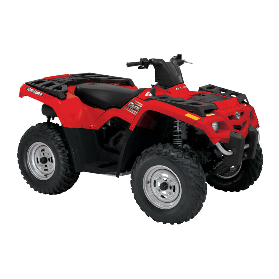
BOMBARDIER OUTLANDER 2004 / XT 2004 / MAX 2004 / MAX XT 2004 Manual
- Shop manual supplement (29 pages)
- Also fits for
- Outlander xt 2004
- Outlander max 2004
- Outlander max xt 2004
Advertisement
INTRODUCTION
This Shop Manual covers the following Bombardier made 2004 ATVs:
| Models | |
| Outlander 400 (viper red) | 8108 |
| Outlander 400 (yellow) | 8110 |
| Outlander 400 XT (yellow) | 8111 |
| Outlander 400 MAX XT (yellow) | 8112 |
| Outlander 400 MAX (viper red) | 8130 |
| Outlander 400 XT (two tones) | 8139 |

TYPICAL — VEHICLE SERIAL NUMBER LABEL
SERIAL NUMBERS LOCATION

- E.I.N. (Engine Identification Number)
- V.I.N. (Vehicle Identification Number)
LIST OF ABBREVIATIONS USED IN THIS MANUAL
| A | ampere |
| amp | ampere |
| A•h | ampere-hour |
| AC | alternate current |
| BDC | bottom dead center |
| BTDC | before top dead center |
| °C | degree Celsius |
| CDI | Capacitor discharge ignition |
| cm | centimeter |
| cm² | square centimeter |
| cm³ | cubic centimeter |
| CVT | Continuously variable transmission |
| DC | direct current |
| °F | degree Fahrenheit |
| fl. oz | fluid ounce |
| ft | foot |
| GRD | ground |
| hal. | halogen |
| I.D. | inside diameter |
| IDI | induction discharge ignition |
| imp. oz | imperial ounce |
| in | inch |
| in² | square inch |
| in³ | cubic inch |
| k | kilo (thousand) |
| kg | kilogram |
| km/h | kilometer per hour |
| kPa | kilo pascal |
| L | liter |
| LH | left hand |
| lb | pound |
| lbf | pound (force) |
| m | meter |
| MAG | magneto |
| Max. | maximum |
| Min. | minimum |
| mL | milliliter |
| mm | millimeter |
| MPH | mile per hour |
| N | newton |
| N.A. | not applicable |
| no. | number |
| 00.0 | continuity |
| O.L. | overload (open circuit) |
| O.D. | outside diameter |
| OHC | Over head camshaft |
| OPT | optional |
| oz | ounce |
| P/N | part number |
| PSI | pound per square inch |
| PTO | power take off |
| RPM | revolution per minute |
| Sp. Gr. | specific gravity |
| TDC | top dead center |
| U.S. oz | ounce (United States) |
| USFD | U.S. Forest Service |
| V | volt |
| Vac | volt (alternative current) |
ILLUSTRATIONS AND PROCEDURES
Illustrations and photos show the typical construction of the different assemblies and, in all cases, may not reproduce all details or the exact shape of the parts shown; however, they represent parts that have the same or a similar function.

Most components in the vehicles are built with parts dimensioned in the metric system. Most fasteners are metric and must not be replaced by customary fasteners or vice-versa. Mismatched or incorrect fasteners could cause damage to the vehicle or possible personal injury.
As many of the procedures in this manual are interrelated, we suggest that before undertaking any task, you read and thoroughly understand the entire section or subsection concerning the procedure.
A number of procedures throughout the book require the use of special tools. Before starting any procedure, be sure that you have on hand all required tools, or approved equivalents.
The use of RIGHT and LEFT indications in the text, always refers to the driving position (sitting on the vehicle).

- Left
- Right
TIGHTENING TORQUES
Tighten fasteners to torque mentioned in exploded views and text. When they are not specified, refer to following tables. The tables also gives the metric conversion.

Torque wrench tightening specifications must be strictly adhered to.
Locking devices (ex.: locking tab, elastic stop nut, self-locking fasteners, etc.) must be installed or replaced with new ones where specified. If the efficiency of a locking device is impaired, it must be renewed.
In order to avoid a poor assembling, tighten screws and bolts in accordance with the following procedure:
- Manually screw all screws, bolts and/or nuts.
- Apply the half of the recommended torque value.
Be sure to use the proper tightening torque for the proper strength grade.
NOTE: When possible, always apply torque on the nut.
- Torque at the recommended torque value.
Where possible, apply the torque on the nut.
NOTE: Always torque screws, bolts and/or nuts in a criss-cross sequence.
| TIGHTENING TORQUE | STRENGTH GRADE | ||||
| Grade 5.8 | Grade 8.8 | Grade 10.9 | Grade 12.9 | ||
| Dimension | M4 | 1.5 to 2 N•m (13 to 18 lbf•in) | 2.5 to 3 N•m (22 to 27 lbf•in) | 3.5 to 4 N•m (31 to 35 lbf•in) | 4 to 5 N•m (35 to 44 lbf•in) |
| M5 | 3 to 3.5 N•m (27 to 31 lbf•in) | 4.5 to 5.5 N•m (40 to 47 lbf•in) | 7 to 8.5 N•m (62 to 75 lbf•in) | 8 to 10 N•m (71 to 89 lbf•in) | |
| M6 | 6.5 to 8.5 N•m (58 to 75 lbf•in) | 8 to 12 N•m (71 to 106 lbf•in) | 10.5 to 15 N•m (93 to 133 lbf•in) | 16 N•m (12 lbf•ft) | |
| M8 | 15 N•m (11 lbf•ft) | 24.5 N•m (18 lbf•ft) | 31.5 N•m (23 lbf•ft) | 40 N•m (30 lbf•ft) | |
| M10 | 29 N•m (21 lbf•ft) | 48 N•m (35 lbf•ft) | 61 N•m (45 lbf•ft) | 72.5 N•m (53 lbf•ft) | |
| M12 | 52 N•m (38 lbf•ft) | 85 N•m (63 lbf•ft) | 105 N•m (77 lbf•ft) | 127.5 N•m (94 lbf•ft) | |
| M14 | 85 N•m (63 lbf•ft) | 135 N•m (100 lbf•ft) | 170 N•m (125 lbf•ft) | 200 N•m (148 lbf•ft) | |
CVT
GENERAL
NOTE: To perform the following instructions, it is not necessary to remove engine.
This CVT is lubrication free. Never lubricate any components except drive pulley one-way clutch.
During assembly/installation, use torque values and service products from the exploded view in 2004 Outlander ATV Shop Manual. Clean threads before applying a thread locker. Refer to SELFLOCKING FASTENERS and LOCTITE APPLICATION at the beginning of this manual for complete procedure.
Never touch CVT while engine is running. Never drive vehicle when CVT cover is removed.
Any drive pulley repairs must be performed by an authorized Bombardier ATV dealer. Subcomponent installation and assembly tolerances require strict adherence to procedures detailed.
Never use any type of impact wrench at drive pulley removal and installation.
The clutch assembly is a precisely balanced unit. Never replace parts with used parts from another clutch assembly.
These pulleys have metric threads. Do not use imperial thread puller. Always tighten puller by hand to ensure that the drive pulley has the same type of threads (metric vs imperial) before tightening completely.
DRIVE PULLEY

- Belt
- Drive pulley
- Driven pulley
Refer to CVT section of 2004 Bombardier Outlander ATV Shop Manual for drive pulley maintenance and repair.
However, ATV models covered by this shop manual supplement are equipped with a kit of 6 centrifugal levers instead of a kit of 4.

- Standard levers
- Supplementary levers
CARBURETOR
GENERAL
Before performing any job on the fuel system, always turn fuel valve to OFF position and disconnect BLACK (-) cable from battery.
Always disconnect battery exactly in the specified order, BLACK (-) cable first. It is recommended to disconnect electrical connections prior to disconnecting fuel lines.
CARBURETOR
Although some jets can be replaced by other jets from other carburetors, such modifications should not be performed. They can greatly affect engine calibration and can cause severe damage to engine. Use only recommended jetting specific for this carburetor.
Carburetor Inspection
Remove carburetor from vehicle (refer to CARBURETOR REMOVAL from 2004 Bombardier Outlander ATV Shop Manual).
Remove carburetor throttle shaft cover.

Make sure that M4 Allen screw is still in place and tight. If not, remove and clean it, pour a drop of Loctite 648 on threads, reinstall and tighten screw.

Needle
On carburetor, remove diaphragm cover and check for proper needle installation. Needle bushing must be above circlip as shown on next photo.

Carefully replace diaphragm in its original position.
Install diaphragm cover. Make sure spring is located properly in carburetor cover before screwing.
Needle Jet
The models covered by this shop manual supplement are equipped with a different needle jet from the other 2004 Outlander ATVs.
| Needle Jet Type | O-0 |
| Bombardier Part Number | 404 162 055 |
| Mikuni Part Number | 785-401003-O-0 |
Reinstall carburetor into vehicle (refer to CARBURETOR REMOVAL from 2004 Bombardier Outlander ATV Shop Manual).
Throttle Cable
Verify also throttle cable adjustment. Refer to THROTTLE CABLE ADJUSTMENT from 2004 Bombardier Outlander ATV Shop Manual.
NOTE: If local laws and regulations restrict vehicle to a maximum speed, adjust throttle screw so that this speed is reached when throttle lever touches the screw.

- Throttle Lever
- Lock Nut
- Throttle Screw
INSTRUMENTS AND ACCESSORIES
REMOVAL AND INSTALLATION
It is recommended to always disconnect the battery when replacing any electric or electronic parts. Always disconnect battery exactly in the specified order, BLACK (-) cable first. Do not place tools on battery.
At installation, use torque values and Loctite products from the exploded view. Clean threads before using Loctite products when reinstalling screws.
Torque wrench tightening specifications must strictly be adhered to.
Locking devices (ex.: locking tabs, elastic stop nuts, self-locking fasteners, etc.) must be installed or replaced with new ones where specified. If the efficiency of a locking device is impaired, it must be renewed.
HEADLAMP
Test
Refer to TESTS section in 2004 Outlander ATV Shop Manual.
Bulb Replacement
Refer to BULB REPLACEMENT section in 2004 Outlander ATV Shop Manual.
Always turn the ignition switch OFF before replacing a bulb or an indicator light.
NOTE: Always check light operation after replacement.
Headlamp
The headlamp has two bulbs, one headlamp bulb and one position lamp bulb.
To replace the headlamp bulb, proceed as follows.
Disconnect the headlamp connector.
NOTE: On the following illustrations, the headlamp has been removed for a better comprehension.

Remove the protective rubber sleeve.

Unlock the bulb socket.

Remove the socket snap. Open the both side of socket snap.

- Housing hole
- Socket slot
Push bulb in and hold while turning counterclockwise to release.
Install the new bulb by first pushing in while turning clockwise.
Install the socket into the headlamp housing. Align holes in the housing with the socket slots.

Install the socket snap.
Install the protective rubber sleeve and connect the headlamp connector.
NOTE: Take care do not pry the socket terminals.

- Headlamp
- Beam height adjustment
- Beam side adjustment
Adjust beam aiming as follows:
Turn knobs to adjust beam height and side orientation to your convenience. Adjust both headlamps evenly.
Position Lamp
Into headlamps, a small bulb is installed aside from main bulb. This position lamp can be changed by pulling it from rear of headlamp.
BRAKE LAMP
Bulb Replacement

- Lens
- Screws
Unscrew lens screws to expose bulb.
Push bulb in and hold while turning courterclockwise to release.
Install the new bulb by first pushing in while turning clockwise.
DIRECTION INDICATOR LAMP
Test
Refer to TESTS section
Bulb Replacement

- Screw
- Lug
Unscrew direction indicator lens.
Push then turn bulb to remove it and replace with a new one.

Reinstall direction indicator lens.
Removal

- Harness
- Nut
Unplug direction indicator wires from harness.
Unscrew nut securing direction indicator housing to its bracket.
Installation
For installation, reverse the removal procedure.
NOTE: Take care to have lens drain hole downward. In other words, because of drain hole position, left front direction indicator is identical to right rear direction indicator and right front direction indicator is identical to left rear direction indicator.
DIRECTION INDICATOR SWITCH
Removal

- Switch
- Screws
- Connector
Unscrew and remove steering cover.
Unscrew both sets of nut and screw retaining switch.
Remove locking ties and unplug connector.
Installation
For installation, reverse the removal procedure.
HAZARD WARNING BUTTON
Removal
Remove console
Unplug wires.
NOTE: Take care to identify wires correctly (see table below).
Unscrew button
Bulb Replacement

Remove rubber cap.

Unscrew plastic button.

Carefully pull the bulb out of the socket and replace with a new one. Make sure bulb leads have a good electric contact with contact plates.
Installation
Insert switch in place and secure it with its nut.
Plug wires as per following:
| WIRE | PIN NUMBER |
| RED/VIOLET | 49 |
| RED/BROWN | 15 and 30b |
| RED/BLACK (coming from battery) | 30 |
| BLACK/RED (coming from flasher module) | 49a |
| RED/YELLOW | 58 |
| GREY/BLACK | L |
| WHITE/BLACK | R |
| BLACK | 31 |
2WD/4WD SELECTOR

- Actuator
- 2WD/4WD Connector (must be unplugged)
On models covered by this shop manual, 2WD mode is inactive because disconnect unit connector is unplugged from the actuator.
Remember that, when riding on public roads, Bombardier Outlander ATV must be set on 4WD mode.
HORN
Removal

- Horn
- Wires
- Front Support
Horn is located on upper left corner of radiator. To remove it, unplug wires and unscrew nut securing horn to front support.
Installation
When installing horn, take care:
- to install horn facing the front of vehicle
- that horn bracket have a 90° bent
- that drain holes are straight upward and downward (to avoid water to stay into the horn body)
HORN BUTTON
Removal
Remove steering cover.
From underneath steering cover, unplug horn button wires then unscrew nut.
Installation
For installation, reverse the removal procedure.
TESTS
DIRECTION INDICATORS
Note: Flashing rate: Approximately 72 cycles per minute. When a bulb is burnt, the flashing rate is doubled.

Direction indicator's pilot lamp
Unscrew console and check pilot lamp's contacts for short circuit or broken wire.
Interchange wires at pilot lamp's contacts. If this doesn't solve the problem, reinstall wires as they were first.
Check voltage at pilot lamp terminals when flashing module is active. Voltage must be on and off 72 times per minute. If not, check wiring.
Direction indicator bulb
Remove bulb.
Check for broken filament. If so, replace bulb.
If not, check for electrical resistance. If multimeter indicates infinite resistance, replace bulb.
If not, check for voltage at direction indicator contacts when key switch is turned on Run/Light mode. If no voltage is measured, harness may be faulty. Using wiring diagram, check electrical systtem.
Direction indicator switch
Cut locking tie, lift sheath and by-pass switch. If this resolves the problem, switch is faulty and must be replaced.
Flashing module
Check for flasher contacts and replace with a new one. If problem persists, flashing module is NOT faulty. Reinstall old module.
Hazard switch
Check contacts for short circuits or broken wires.
Repair any impaired wire or part.
Harness assembly
Using wiring diagram, check for short circuits or broken wires. Repair any impaired wire or part.
STEERING SYSTEM
GENERAL
During assembly/installation, use torque values and service products from the exploded view in 2004 Bombardier Outlander ATV Shop Manual. Clean threads before applying a threadlocker. Refer to SELF-LOCKING FASTENER and LOCTITE APPLICATION at the beginning of this manual for complete procedure.
Torque wrench tightening specifications must strictly be adhered to.
Locking devices (ex.: locking tabs, elastic stop nuts, self-locking fasteners, etc.) must be installed or replaced with new ones where specified. If the efficiency of a locking device is impaired, it must be renewed.
HANDLEBAR
Removal
Remove:
- handlebar covers
- right and left rear mirrors (see below in this section)
- handlebar grips
- brake handle (see STEERING/CONTROLS SYSTEMS in 2004 Bombardier Outlander ATV Shop Manual)
- throttle handle and multi-function switch (see STEERING/CONTROLS SYSTEMS in 2004 Bombardier Outlander ATV Shop Manual)
NOTE: Remove handlebar grips, throttle handle and multi-function switch only if the handlebar is defective and have to be replaced with a new one.
- steering clamp mounting bolts and steeringclamp
- handlebar.
Inspection
Inspect the handlebar for damage, cracks or bending, replace if any of these problems is detected.
Installation
For the installation, reverse the removal procedure.
RIGHT AND LEFT REAR MIRRORS
Removal

- Left side mirror
- Lock washer
- Mirror support
Unscrew mirror stem from mirror support.

- Right side mirror
- U-clamp
- Lock washer
- Nut
Installation
Left side
Make sure mirror support is tighten then screw mirror stem into mirror support.
Right side
Secure right side mirror using U-clamp, lock washer and nut.
TECHNICAL DATA
| VEHICLE MODEL | OUTLANDER TM 400 / 400 XT / MAX / MAX XT | ||
| ENGINE | Refer to 2004 Bombardier Outlander ATV Shop Manual | ||
| ELECTRICAL | Refer to 2004 Bombardier Outlander ATV Shop Manual except for: | ||
| Head lamp | 35 W | ||
| Brake lamp | 10 W | ||
| Position lamp | 4 W | ||
| Direction indicator | 10 W | ||
| Pilot lamp cluster | LEDS, 0.7 V approximately (each) | ||
| CARBURETION | Refer to 2004 Bombardier Outlander ATV Shop Manual except for: | ||
| Needle jet | 785 - 401003 - 0 - 0 | ||
| COOLING | Refer to 2004 Bombardier Outlander ATV Shop Manual except for: | ||
| Engine thermostat | Opening temperature | 65°C (149°F) | |
| Closing temperature | 75°C (167°F) | ||
| LUBRICATION DRIVE TRAIN STEERING/CONTROL SUSPENSION BRAKES TIRES AND WHEELS DIMENSION | Refer to 2004 Bombardier Outlander ATV Shop Manual | ||
| CAPACITIES | Refer to 2004 Bombardier Outlander ATV Shop Manual except for: | ||
| BODY AND FRAME | |||
| Gross vehicle weight rating | 460 kg (1014 lb) | ||
| Towing | 135 kg (300 lb) | ||
| MATERIAL TORQUE | Refer to 2004 Bombardier Outlander ATV Shop Manual | ||
WIRING DIAGRAM

WIRING CONNECTORS CODING
Ensure all terminals are properly crimped on the wires and all connector housings are properly fastened.

- Wire colors
- Connector housing area
- Connector number
- Wire connector location in housing
WIRE COLORS
It identifies the color of a wire. When a 2-color scheme is used, the first color is the main color while the second color is the tracer color.

Example: YL/BK is a YELLOW wire with a BLACK stripe.
CONNECTOR HOUSING AREA


| AREA | LOCATION |
| 1 | Steering area |
| 2 | Service compartment |
| 3 | Front of vehicle |
| 4 | Engine area |
| 5 | Rear of vehicle |
CONNECTOR NUMBER
It represents a connector number in the given area. If there are many connectors in the same area, it helps identify which wire is in which connector.

CONNECTOR LOCATION IN HOUSING
This is the wire position in the connector. The number or letter given refers to the physical identification stamped on the connector.
NOTE: However, if no letters or numbers are indicated on the connectors, see the connector chart at the end of the OVERVIEW section for proper connector locations.

LEGEND

SAFETY NOTICE
This manual has been prepared as a guide to correctly service and repair 2004 Bombardier Outlander ATVs riding within the European Community. This supplement must be used in conjunction with the 2004 Bombardier Outlander ATV Shop Manual (P/N 219 100 180).
This edition was primarily published to be used by ATV mechanical technicians who are already familiar with all service procedures relating to Bombardier made vehicles. Mechanical technicians should attend continuous training courses given by Bombardier Training Department.
Please note that the instructions will apply only if proper hand tools and special service tools are used.
This Shop Manual uses technical terms which may be slightly different from the ones used in Parts Catalog.
It is understood that this manual may be translated into another language. In the event of any discrepancy, the english version shall prevail.
The content depicts parts and/or procedures applicable to the particular product at time of writing. Service and Warranty Bulletins may be published to update the content of this manual. Make sure to read and understand these. It does not include dealer modifications, whether authorized or not by Bombardier, after manufacturing the product.
In addition, the sole purpose of the illustrations throughout the manual, is to assist identification of the general configuration of the parts. They are not to be interpreted as technical drawings or exact replicas of the parts.
The use of Bombardier parts is most strongly recommended when considering replacement of any component. Dealer and/or distributor assistance should be sought in case of doubt.
The engines and the corresponding components identified in this document should not be utilized on product(s) other than those mentioned in this document.
This manual emphasizes particular information denoted by the wording and symbols: Identifies a potentially hazardous situation which, if not avoided, could result in serious injury or death
Identifies a potentially hazardous situation which, if not avoided, could result in serious injury or death
Denotes an instruction which, if not followed, could severely damage vehicle components.
NOTE: Indicates supplementary information needed to fully complete an instruction.
Although the mere reading of such information does not eliminate the hazard, your understanding of the information will promote its correct use. Always use common shop safety practice.
This information relates to the preparation and use of Bombardier ATV and has been utilized safely and effectively by Bombardier Inc. However, Bombardier Inc. disclaims liability for all damages and/or injuries resulting from the improper use of the contents. We strongly recommend that any services be carried out and/or verified by a highly skilled professional mechanic. It is understood that certain modifications may render use of the vehicle illegal under existing federal, provincial and state regulations.
Torque wrench tightening specifications must strictly be adhered to.
Locking devices (ex.: locking tabs, elastic stop nuts, self-locking fasteners, etc.) must be installed or replaced with new ones where specified. If the efficiency of a locking device is impaired, it must be renewed.
Documents / ResourcesDownload manual
Here you can download full pdf version of manual, it may contain additional safety instructions, warranty information, FCC rules, etc.
Download BOMBARDIER OUTLANDER 2004 / XT 2004 / MAX 2004 / MAX XT 2004 Manual
Advertisement


Need help?
Do you have a question about the OUTLANDER 2004 and is the answer not in the manual?
Questions and answers