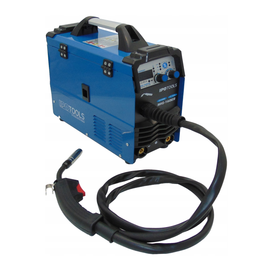
IPOTOOLS MIG-160ER Manual
- Instruction manual (17 pages) ,
- Instruction manual (145 pages)
Advertisement
- 1 SAFETY MEASURES
- 2 MAIN FUNCTIONS
- 3 TECHNICAL INFORMATION
- 4 OPERATING CONDITIONS & WORKING ENVIRONMENT
- 5 BEFORE STARTING WORK
- 6 CONTROL PANEL
- 7 WELDING WIRE INSTALATION
- 8 CONNECTION & SETTINGS
- 9 WELDING TIPS
- 10 WHICH WELDING WIRE TO USE FOR MIG MAG WELDING
- 11 TROUBLESHOOTING
- 12 MANUFACTURER WARRANTY
- 13 Documents / Resources
SAFETY MEASURES

Improper use of any welding machine can result in injury or death.
CONNECT THE WELDING APPLIANCE ONLY TO THE APPROPRIATE ENERGY SOURCE. This information is given on the rating plate on the welding machine. When welding outdoors, use only an extension cord designed for such use.
WORK WITH THE APPLIANCE ONLY ON A DRY AREA AND ON A SOLID GROUND. Make sure the work area is clean and tidy.
MAKE SURE THERE ARE NO FLAMMABLE SUBSTANCES IN THE WORKING AREA.
KEEP CLEAN CLOTHES WITHOUT TRACE OF GREASE OR OIL AT WORK.
MAKE SURE THE CABLES DO NOT COME INTO CONTACT WITH GREASE OR OIL and never wrap them around your shoulders.
SAFE WORK WITH CLAMPS or in other means, do not overdo it.
NEVER ESTABLISH AN ARCH ON A PRESSURE GAS TANK.
THE UNINSULATED PART OF THE ELECTRODE HOLDER SHOULD NEVER TOUCH THE GROUND WHILE THE CURRENT IS FLOWING!
IT IS NECESSARY TO TURN OFF AND DISCONNECT THE CABLES WHEN REPAIRING OR ADJUSTING THE APPLIANCE. Check the device before each use. Use only original spare parts.
FOLLOW ALL MANUFACTURER'S RULES regarding modification, and adjustment of the device.
APPROPRIATE PROTECTIVE NON-FLAMMABLE CLOTHING AND FOOTWEAR AGAINST HEAT AND FLAMMES MUST BE CARRIED AT WORK. The welder should be dressed in a work suit made of non-combustible fibbers during welding. The dress should be dry, clean, not too loose and without cut-outs or pockets. Shoes should be closed, high. The use of non-flammable gloves, a hat, a protective mask, and a leather apron is mandatory. Low shoes, self-made fibber dresses and short gloves are not suitable for welding.
ALWAYS WARE A WELDING MASK WITH APPROPRIATE EYE PROTECTION WHEN WELDING. Sparks can cause blindness during welding, so always wear protection under the welding mask.
BE CAREFUL OF HOT METAL PARTS, ESPECIALLY WHEN WELDING OVER YOUR HEAD. Always wear head, arm, leg, and body protection.
MAKE SURE YOU HAVE A FIRE EXTINGUISHER ALWAYS AT YOUR HAND.
DO NOT SKIP THE MACHINE OPERATING CYCLE. The estimated cycle of the welding machine is a percentage of ten minutes, with this in mind the machine can operate safely in terms of output power.
PREVENT CHILDREN, ANIMALS AND THIRD PARTIES FROM ACCESSING THE WORK AREA. When storing equipment, make sure it is out of the reach of children.
 PROTECT YOURSELF AGAINST ELECTRIC SHOCK. Do not work when you are tired or under the influence of drugs, alcohol, or other illicit substances. Do not allow the body to come into contact with grounded surfaces.
SPECIAL WARNINGS:
- Welding is not allowed in rooms with flammable and explosive materials,
- it is not allowed to weld in / on containers where there were gases, oils, paints...,
- more demanding welds should be welded only by certified welders,
- persons with a pacemaker should consult a doctor before welding.
Before welding, always make sure that all regulations and instructions for safe work are met.
When welding by MIG / MAG process, the noise can be higher than 85db (A), so the worker must wear non-flammable earmuffs during welding.

Welding produces strong UV rays that can burn uncovered parts of the body.
The protective glass on the mask should be numbered 9-15 according to DIN 4647.
Do not look into the electric arc during welding, as there is a risk of instantaneous glare.
Only weld when there is another person nearby who can give you first aid in case of injury.
PEOPLE IN THE VICINITY MUST FOLLOW THE INSTRUCTIONS ABOVE!
In the rooms where we weld, it must be sufficiently airy, suction is desirable. Ventilation device to protect against particles must be available during welding. Toxic gases are formed especially when we weld material that is galvanically coated with other metals or materials with detergent residues. Do not weld closed containers containing flammable liquids (petrol, oil, varnishes...) as there is a high risk of explosion!
FIRE HAZARD
Follow these instructions:
- Remove combustible materials within 5m of the welding site
- Cover openings, cracks, and other objects that can trap sparks
- Keep fire extinguishers nearby
- After welding, inspect the welding area again
- Do not weld on containers with flammable liquids
Shielding gas cylinders must be protected against mechanical damage and excessive heat (max. 50 C). cylinders must also be protected from frost.

DANGERS OF ELECTRIC CURRENT
The device can only be connected to the mains with a shielded connection cable. The fuse must be of the same power as specified in the technical data of the device. The fuse design must be slow.
Replace damaged torch parts, cable ground, or damaged mains connector immediately. Replacement of parts on the network, replacement of the connecting cable can only be performed by an authorized person. Never hold the burner under your arm or otherwise wrapped around your body. In the event of prolonged work interruptions, switch off the appliance and close the shielding gas supply.
In the event of an accident, immediately pull out the plug of the connecting cable!
PURPOSE AND USE
The IPOTOOLS MIG160ER is a welding machine with two welding functions. You can use it for MMA and MIG / MAG welding. Any other use may endanger the safety of the welder or cause the device to malfunction! Use of the device in violation of these operating instructions is not permitted! Damage to the device resulting from improper use is not covered by the warranty statement. The machine can be used to weld several materials, such as steel and stainless steel. The welding current is stable and stepless adjustable. The appliance provides a beautiful weld, and the welding itself takes place quietly and without spattering. The device is small in size, light and thus easy to transport.
MAIN FUNCTIONS
 | MIG MAG WELDING Direct current (DC) gas protection welding with inert gas "MIG welding" (e.g. – argon) or with active gas "MAG welding" (a mixture of carbon dioxide CO2 and argon) |
 | WELDING WITH FLUX CORED WIRE Welding with FLUX cored wire (welding without protective gas) |
 | MMA Welding with stick electrodes |
 | DIGITAL DISPLAY Digital control of the individual welding parameters |
 | INVERTER Modern IGBT technology, which provides high power and long duty cycle |
TECHNICAL INFORMATION
| Type | MIG MAG Inverter Welding Machine MIG-160ER |
| Welding procedures | MMA & MIG/MAG, LIFT TIG |
| Connection voltage | 230V 1-Phase / Frequency: 50/60Hz |
| Housing protection | IP21S |
| Overload display | Yes |
| Cooling | Fan |
| Magnetic valve | Yes |
| MIG Duty Cycle | 160A – 60% / 125A – 100% |
| MMA Duty Cycle | 160A – 60% / 125A – 100% |
| Welding current MIG | 40-160A / MMA: 40-160A |
| No-load Voltage | 60 – 65 V |
| Welding Wire Ø MIG | 100mm / Wire Ø MIG: 0,8/1,0mm |
| Wire feed | 2 Wheels (1 with drive) |
| Max. welding wire diameter Ø | 0,6mm / 0,8mm / 0,9mm / 1,0mm |
| MMA electrode diameter | 1-4mm |
| Dimensions | 360x150x350mm |
| Weight | 8 kg |
Note: The above parameters may change with future machine improvements!
OPERATING CONDITIONS & WORKING ENVIRONMENT
- Operating conditions:
- Voltage, voltage source: AC 220 V/230V/240V,
- Frequency: 50/60Hz,
- Reliable grounding.
- Work environment
- Relative humidity: not more than 90%,
- Ambient temperature: -10 ℃ ~ 40 ℃,
- The welding site must not contain any harmful gas, chemicals, mold and flammable substances, explosive and corrosive media. The welder must not be subjected to any vibration or other disturbances,
- Avoid rain and water, work in such circumstances is prohibited.
BEFORE STARTING WORK
Before welding, it is necessary to read and understand the instructions of use,
Check the machine for any defects or damage,
To ensure the safety of persons and equipment, it is necessary to properly install the earthing with a 4 mm2 conductor, depending on the requirements of the power supply system,
Welding must take place in a dry and well-ventilated area. Objects in the vicinity must be at least 0,5 m away from the appliance,
Check that all cables are tightly fastened / connected,
The appliance must not be moved while the appliance is switched on and welding is in progress.
The appliance must be maintained, used, and operated by a qualified person,
Distribution board current: less than 40A.
CONTROL PANEL
Description of the control panel and the front and back of the appliance:

- Digital display: Amps
- Overload display
- Choice: FLUX / MIX / Co2 / LIFT TIG / MMA
- Control knob: Wire / ampere feed
- Control knob: Voltage (deviation +/- 10V)

- Control panel
- Connection "+"
- Connection "-"
- On / off switch
- Connection cable
- Shielding gas supply

- "+" Pol
- "-" Pol
- Star grip (tension lever)*
- Welding wire reel holder

You can see more on our website!
* Be careful not to overtighten the tensioner lever when mounting the wire!
WELDING WIRE INSTALATION
- Open the door on the side of the device, move the star knob towards you and lift the lid of the clamping system.
- Make sure that, depending on the welding wire diameter, the appropriate wire feed roller (e.g. 0.8mm, 1,0mm, etc.) is in the wire feed system (the wire feed roller side with the correct mm specification must point towards the wire feed).
- Unscrew the screw of the wire locating pin, place the corresponding welding wire on the wire locating pin and retighten the screw (The welding wire must be positioned so that it enters the wire feeder from its lower part.)

- Guide the welding wire into the right opening of the wire feeder, over the wire feed roller into the left opening of the wire feeder.
- Close the cover of the clamping system and move the star grip away from you so that the cover is locked. Adjust the tensioner with the star grip (e.g., with 0,9 mm wire to 3.5). Do not turn the tensioner past value 5!
- The next step is to turn on the unit, make sure the torch cord is straight and remove the nozzle and nozzle assembly from the gun.
- You can then pull the wire to the torch nozzle either with the button on the torch or with the "Fast Wire Drive" button. After the wire comes out of the gun, reattach the nozzle and nozzle assembly to the gun.

CONNECTION & SETTINGS
MIG/MAG welding with/without gas

Connect the torch and the earth cable correctly, depending on whether you want to weld with or without gas (filler wire).
Filled wire welding (without gas)
Set the appliance to "FLUX" by pressing the button (3) ![]()
In this welding process, a filled wire is used for welding, which already contains particles that form a protective atmosphere during welding and thus prevent air from entering. You do not need shielding gas for this welding process.
When you select FLUX, the welding machine automatically adjusts some parameters to help you achieve the best results during welding.
Use the control knob (4) to set the appropriate welding current, which is usually set in the range of approx. 80A when filling with charged wire. Then place the control knob (5) in the middle. During welding, both control buttons must be adjusted until you get a satisfactory or a desired weld.
Shielding gas welding
Depending on which shielding gas you want to work with, press the button (3) to set the "Co2" or "MIX" selection: 
If you use CO2 as the shielding gas, set the "Co2" setting with the button, or if you use the argon/ CO2 mixture as the shielding gas, you must select the "MIX" setting with the key.
Use the control knob (4) to set the appropriate welding current depending on the diameter of the welding wire. Then place the control knob (5) in the middle. During welding, both control buttons must be adjusted until you get a satisfactory or. of the desired weld.
MMA Welding

Connect the welding cable and the earthing cable to the socket (7, 8) with the appropriate polarity according to the electrode manufacturer's recommendation.
Pay attention to positive and negative attachment. Different types of electrodes require different polarities, see electrode manufacturer's instructions.
* In TIG mode (LIFT TIG), connect the cables in the same way as in the case of "A rutile electrode ".
Polarity:
The polarity depends on the information provided by the electrode manufacturer on the electrode packaging.
Electrode NEGATIVE / workpiece POSITIVE - low-alloy rutile electrode types. (These are the most commonly used)
Electrode POSITIVE / workpiece NEGATIVE - basic and high-alloy electrode types.
Connect the power cord to the appropriate voltage and power source and ensure the cord is secure.
The device can now be switched on by operating the on/off switch on the back and thereby putting it into operation.
Electrode Welding
Electrode welding or MMA welding is one of the oldest welding processes that uses stick electrodes that protect the melt from chemical reactions with the ambient air. In this process, an arc burns between an electrode and the workpiece, melting the electrode into a filler material.
Electrode Diameter
Depending on the electrode diameter, you determine the desired current range in which you will be welding. You set the amperage on the front of the device with the welding control button, which you can also read on the digital display. To know which area to select, refer to the information in the table below.
| Stick electrode Ø mm | Current | |
| MIN | MAX | |
| Ø1,6mm | 44A | 84A |
| Ø2,0mm | 60A | 100A |
| Ø2,5mm | 80A | 120A |
| Ø3,2mm | 100A | 150A |
| Ø4,0mm | 140A | 180A |
LIFT TIG mode
Press the button (3) to select the "LIFT TIG" mode: 
In Lift TIG mode, it can be welded according to the TIG process with the optional TIG burner (not included in the package).
In this mode, the corresponding welding current can only be set with the control knob (4).
WELDING TIPS
Stainless steel welding
Note that it is essential to use clean gases (e.g., argon) when welding stainless steel. The setting of the welding current can be adjusted in the same way as for steel welding.
Recommended types of shielding gas:
Steel: CO2, it is also possible to use mixtures, e.g., 18% argon and 82% CO2
WHICH WELDING WIRE TO USE FOR MIG MAG WELDING
A MIG welding wire is indispensable for arc welding because it is inserted into the construction during welding and thus creates a strong connection. MIG welding wires are located on wire rolls and are differentiated depending on the material, roll and wire diameter. When choosing the right MIG welding wire, you must consider the material composition, the quality, and the suitable wire diameter for the welding current. As a rule, the thicker the welding wire, the stronger the materials that can be welded with it. However, the material composition, which depends on the application, is particularly important when making the selection. The right choice depends on the material and material thickness that you want to weld. The rule applies that the additional material is the same as the material of the workpiece. You can choose from the following types of welding wire:
Solid wire - Solid wire refers to welding wires such as steel and stainless steel, which require a protective gas to prevent oxidation during the welding process. The shielding gas guarantees a stable arc and protects the liquid weld pool from the ingress of air from the atmosphere. This variant is used by more than 80% of users because it produces less spatter, and the seams are of better quality than those produced by welding without gas. Solid wires are also gentler on the wire feed in the device due to their higher column cross-section strength, they are also stiffer and do not bend as easily. A gas cylinder, a manometer and a wire feed roller with a V-groove are used for welding with solid wire. The protective gas used for steel (82% argon and 18% CO2) and stainless steel (97.5% argon and 2.5% CO2).
Cored Wire / FLUX / Gasless Wire - These wires consist of a thin metallic jacket that is filled with powder and layered with metal compounds and then rolled into a cylinder to shape the finished wire. At high temperatures, the FLUX wire creates an atmosphere with protective gas, which means that you do not need a gas cylinder or manometer for use. The cored wire is softer than the solid wire and behaves in a similar way to the aluminium wire when it is fed to the workpiece, which can mean less safety in feeding and possible crushing of the wire when it exits the drive. For cored wire, you will find special knurled wire feed rollers which have small teeth in the groove so that the wire is better gripped and thus a better feed is created, but over time the surface of the welding wire will slowly erode, which can lead to blockages in the wire guide A U-groove roller for cored wire can also be used, thanks to which one can avoid a blockage at the price of lower feed quality. Compared to solid wire, cored wire welding has the advantage that you do not need any accessories for gas, you can also do work outside, but there are also disadvantages because this method creates more spatter, the slag must be removed, and the quality of the seams is poorer than with inert gas welding. Shielding gas is not used for cored wire.
TROUBLESHOOTING
Our welding machines are always tested and calibrated before shipment. Any unauthorized modification of the device is prohibited and has a negative effect on the guarantee!
The modifications can only be caried out by the technicians of the sales company!
The operating instructions must be read carefully to ensure that there are no unintended complications that could endanger the user.
Before starting any repairs, it is necessary to switch off the welding machine!
If there is a problem with the device and there is no authorized specialist in your place of residence, it is best to contact the seller.
For simple problems and errors on the welding machine, please follow the table below:
| Nr. | Defect | Cause | Solution |
| 1 | No function | Micro fuse defective | Replace micro fuse: 2.5 A (3.15 A) |
| Wrong power connection | Have the connection checked by a specialist | ||
| 2 | Irregular wire feed | Wrong contact pressure on the feed roller | Set the correct pressure (it must be possible to block the wire roll by hand) |
| Wire guide on the feed motor not in a line | Bring the feed roller and wire guide into line | ||
| Guide spiral blocked or not suitable for wire size | Check, possibly change | ||
| Badly coiled wire or wire crossings | Replace the wire roll | ||
| Rusted wire or poor quality | Replace the wire roll, clean or replace the guide spiral | ||
| Too much tightened mandrel brake | Release mandrel brake, screw on | ||
| The feed roller is dirty | Clean the feed roller | ||
| Feed roller worn or not suitable for wire size | Replace the feed roller | ||
| 3 | Brittle or porous weld seam | Gas hose connections leaky | Check connections |
| Empty gas bottle | Fill up the gas bottle | ||
| Gas tap closed | Open the gas tap | ||
| Defective pressure reducer | Check pressure reducer | ||
| Solenoid valve defective | Test the voltage at the solenoid valve (220 volts) | ||
| Gas nozzle on burner or hose package clogged | Clean the gas nozzle and grease the burner with nozzle grease or spray with nozzle spray, blow out the hose package | ||
| Draft at the welding point | Shield the welding point or increase the gas flow. | ||
| Dirty workpiece | Remove rust, grease or paint | ||
| Bad wire quality or unsuitable shielding gas | New welding wire, use suitable shielding gas or mixed gas | ||
| 4 | Constant gas leakage | Solenoid valve defective, foreign body in the valve | Clean or replace solenoid valve |
| Hose is not tight | Fasten hose clamps | ||
| 5 | No wire feed when the fan is running | Microswitch in the torch or control line in the hose package is defective | Bridging the two small contacts in the central connection with a piece of wire |
| Control board defective | Reset the control board | ||
| Fine fuse at the control transformer defect | Replace micro fuse (1 A) | ||
| 6 | Wire feed cannot be regulated, motor only runs at 1 speed | Control board defective | Reset the control board |
| 7 | No welding current when the feed is working normally | Main contactor defect | Check line contactor, replace if necessary |
| Step switch defective | Measure the step switch function | ||
| Ground cable or hose package is not making contact | Check ground cable and hose package connection and pliers for contact | ||
| Overload protection has turned on | approx. 10-20 min cooling with the fan motor running | ||
| 8 | An arc is created as soon as the gas nozzle is touched | Short circuit between electricity and gas nozzle | Clean the gas nozzle and torch neck and spray with welding spray |
| 9 | Torch gets too hot | Contact tip too big or loose | Use a contact tip suitable for the wire size or screw the tip tight |
| 10 | Insufficient welding current | Bad contact | Check ground cable and pliers or hose package, replace if necessary |
MANUFACTURER WARRANTY
MANDATORY WARRANTY
Guarantor
The guarantor is the company:
IPO Technik-Handels GmbH
Otto-Lilienthal-Str. 4
88046 Friedrichshafen
Germany
Email: info@ipotools.eu
Website: www.ipotools.eu
The guarantee has to be claimed against the guarantor.
ADDITIONAL MANUFACTURER WARRANTY
Assertion
The warranty is to be asserted for customers who have purchased directly from IPO Technik-Handels GmbH by sending the repair request in text form (e-mail or letter) to IPO Technik-Handels GmbH and sending the device to IPO Technik-Handels GmbH to the following address:
IPO Technik-Handels GmbH
c/o K36302 LogoiX
Wasserburger Str. 50a
83395 Freilassing
Germany
For the assertion of the guarantee the presentation of the original invoice, from which the product and buyer data result, is a requirement.
IPO Tecnik-Handels GmbH
Otto-Lilienthal-Str. 4
88046 Friedrichshafen
Germany
Europe:
W: www.ipotools.eu
E: info@ipotools.eu
Documents / Resources
References
Download manual
Here you can download full pdf version of manual, it may contain additional safety instructions, warranty information, FCC rules, etc.
Advertisement


Need help?
Do you have a question about the MIG-160ER and is the answer not in the manual?
Questions and answers