UeeVii CPE450 Manual
- Quick installation manual (16 pages) ,
- User manual (36 pages) ,
- User manual (15 pages)
Advertisement
Basic Settings
Note: If you are a non-technical person, just read the basic settings
Introduce
UeeVii CPE450 is a long-distance 5.8G wireless transmission device. It uses wireless communication technology to transmit network data using air as a medium to perform long-distance point-to-point or point-to-multipoint interconnection. The working data link layer realizes the interconnection of local area networks. The transmission distance can reach up to 3km.
CPE450 Video Bridge Transmission usually consists of two devices in AP and Client mode respectively. On the Client-side (Receiving side) CPE connects with IP Camera, at the AP side (Transmitting side) CPE connects with a video recorder. The AP can be receiving wireless data transmitted from multiple Clients, and it is easy and convenient for centralized management of the remote equipment.
CPE is widely used in highways, reservoir river monitoring, elevator monitoring systems, site crane monitoring systems, port terminal monitoring systems, marine aquaculture monitoring systems, and so on.
Point to point extend network WiFi range, extend the network in the house to your barn, garage, church, warehouse, and even neighbor's house through wireless bridge signal transmission. No need to install a new modem and pay for it every month, saving you money.
Highlights
- Long-distance 5.8G wireless transmission bridge.
- Support point-to-point, point-to-multipoint mode.
- 14dbi high-gain antenna, power automatic adjustment.
- Transmission distance up to 3km(Barrier-Free).
- WDS networking mode, video network dual compatible.
- Dialing to pair the transmitter and receiver.
- Support PC browser to access and modify the device.
- 24V~48V PoE power supply, efficient power saving.
Package List

2 * CPE450 Wireless Bridge
2 * POE Adapter (24V)
2 * Network Cable
2 * Metal Hoop
1 * User Manual
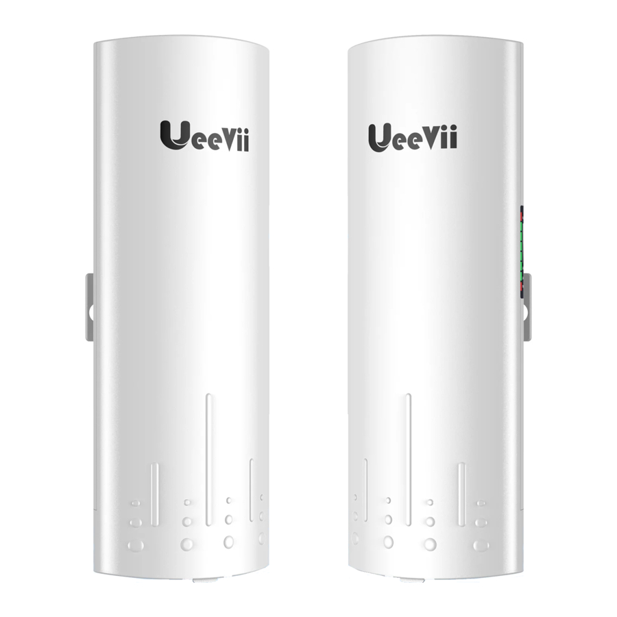
Details Part

Part Description
| Item | Description |
| WLAN Signal LED | WLAN and 4 grid green signal strength display. |
| LAN1/LAN2 | When LAN1 and LAN2 are connected is flashing. |
| PWR | Power indicator, red LED solid is normal. |
| Digital Tube | Digital tube display "H" indicates in manual configuration status. |
| Digital Tube | Digital tube display "L" and flashing indicates in settings status. |
| Digital Tube | Digital tube flashing indicates setting the config or connecting, solid light indicates that the pairing has been successful. |
| Point LED | A, B status lights, lighting is B mode, no lighting is A mode. |
| RST Button | Click once to switch between different characters, looping from 0, 1, ..., F. Characters represent channels. |
| RST Button | Long-press 10s on the "RST" button and the bridge will auto-reset. |
| A-B Button | The bridge switches the master and slave bridges through the A-B button, A represents the master bridge, and B represents the slave bridge. |
| LAN1 LAN 2 Port | Support data transmission and POE power supply, 10/100Mbps RJ45 port. |
| POE Port of the injector | 24V~48V PoE power supply and data transmission. |
| LAN Port of the injector | Only data transfer, 100Mbps RJ45 port. |
PoE Power Supply
The wireless bridge adopts a PoE power supply, which is easy to install and manage while saving costs.

- The LAN port of the PoE power supply is connected to the PC, router, and switch.
- According to the requirements, prepare a long enough network cable(Recommended within 20 meters, must Cat 5e or up) to connect the wireless bridge and the PoE power supply. The PoE port of the PoE power supply is connected to the LAN/PoE port of the wireless bridge.
- Must use attached 24V~48V PoE power supply, and support 48V PoE injector and 48V PoE switch power supply (transferable data). Support 12V~1A DC power supply, not included.
Connection Method
- Transmit wireless network signal
Digital Bridge-A Master Mode

Digital Bridge-B Slave Mode

- Transmission of video signals
Digital Bridge-A Master Mode

Digital Bridge-B Slave Mode


Dial Pairing Guide
- Point to Point Pairing Step:
- Switch one unit to A (Master Bridge) and one unit to B(Slave Bridge);
- Connect the POE to each unit using the Ethernet cable and plug the POE in;
- Wait for them to power up, about 2 min;
- Use the tiny reset button to click through until you get a channel with a letter. 1,2,3,..., A,B,C,...,F, here used C;
- Then on the other unit do the same. Both units need to be on the same channel;
- Wait for 2-5 minutes to complete the pairing. When the number of the digital tube is solid and the signal light on the side turns on, it means the pairing is successful;
- Finally connect other devices (Router, PC, Switch) and install them to the target location.
- Point to Multipoint Pairing Step:
e.g. 1 master bridge with 3 slave bridges- Switch one unit to A (Master Bridge) and 3 units to B(Slave Bridge);
- Connect the POE to each unit using the Ethernet cable and plug the POE in;
- Wait for them to power up, about 2 min;
- Use the tiny reset button to click through until you get a channel with a letter. 1,2,3,..., A,B,C,...,F, here used C;
- Then on the other 3 unit do the same. 4 units need to be on the same channel;
- Wait for 2-5 minutes to complete the pairing. When the number of the digital tube is solid and the signal light on the side turns on, it means their pairing is successful;
- Finally connect other devices (Router, PC, Switch) and install them to the target location.
Installation

- Place the CPE to the selected position and adjust the CPE front panel orientation to be approximately the same as the selected direction, then use the ties to fix the CPE, the bracket is not included in the package. Recommended UeeVii Universal Bracket (ASIN: B09Y56M6Z9).
- Please, prepare a long enough network cable to connect the PoE adapter and CPE, the network cable is connected to the LAN port of the CPE, and the other end is connected to the PoE port of the PoE adapter. Recommend to use a cat 5e (or above) shielded network cable with a ground wire.
- Connect the PoE adapter PoE to CPE, and LAN to Camera, PC, Router or Switch based on the network topology. The role of PoE is to provide power and data transmission for CPE.
- The LAN port on the master CPE's PoE adapter connects to the internet or monitors, while the LAN port on the slave CPE's PoE adapter connects to cameras, routers, or other devices.
WiFi Function
- The WiFi function is turned on by default for the master bridge.
WiFi SSID: CPE5G-5GXXX
WiFi PWD: zllinkcpe123456XXX
XXX represents different channels, please refer to the comparison table in the user manual. - You can access the wireless bridge through your computer to set the SSID and new WiFi password. Please refer to the advanced settings section.
Application Case Topology Diagram
Case 1: Point-to-point extended network WiFi range
suitable for extending the network to second buildings, such as garages, shops, barns, etc.

Case 2: Point-to-point extended of surveillance cameras range

Case 3: Point-to-multiple point extended surveillance cameras range

Case 4: Point-to-point extended surveillance cameras range

Case 5: Work with Starlink

Case 6: Repeater mode obstacle avoidance transmission
A1 and B2 are blocked by mountains and cannot transmit directly. They can be relayed through 2 pairs of bridges.

Advanced Settings
Note: You can work the wireless bridge without advanced settings
Connect Computer and Power Supply
Computer access wireless bridge, connect the CPE to the computer.
Refer to the figure left to connect the CPE to the computer through a PoE adapter and an Ethernet cable.

How to Change Your IP Address on Windows
- Modify your computer's IP address, make your computer's IP and the bridge's IP address be on the same network segment(LAN) so that you can access them.

- Find and open "Open Network and Sharing Center" on your computer.
Tips: click the network icon in the lower right corner of the computer. - Find and open the "Change adapter settings", select "Local Area Connection" to right-click to open the network properties. Refer to the picture above to open.
- Find and double-click open the "Internet Protocol Version 4( TCP/IPv4)", choose the "Use the following IP address" and enter IP address, subnet mask, Default gateway, Preferred DDS server.
- Find and open "Open Network and Sharing Center" on your computer.
- Change your computer's IP address to 192.168.255.xxx (192.168.255.xxx cannot be the same as the IP of the CPE), then the entry IP address is 192.168.255.xxx, the subnet mask is 255.255.255.0(Autofill), the Default gateway is 192.168.255. xxx, Preferred DDS server 192.168.255.xxx. You can use 192.168.255.105(xxx=2) in the reference picture to set.
![]()
- On the login screen, the default user name and login password of the wireless bridge is "admin", just entry password login.
Note: "admin" is not the password of the WiFi SSID, it is just the password for WEB access. - Login successful, go to setting.
![]()


How to Change Your IP Address on Mac
- Click the Apple icon in the upper-left corner of the screen, and select System Preferences.

- Click Network.

- Click your current network on the left and then click Advanced in the lower-right corner of the window.

- Click the TCP/IP tab.

- Click the drop-down box next to Configure IPv6 (or IPv4) and select Manually.

- Enter the IP address you want to use (enter 192.168.255.6; Router 192.168.255.1), and click OK.

- Verify that your new local IP address is displayed and click Apply.


Hide WiFi SSID
In the wireless settings, select "Hidden", and finally click "Apply" to complete the setting.

Setting Options (optional)
- DIP Switch Function

The function of the DIP switch is to control the pairing by dialing the digital switch, making the pairing simple;
When the DIP switch is turned on, pairing can be done through dialing, but any modified wireless bridge parameters cannot be saved when the power is turned off or restarted, and the default parameters must be used;
When the DIP switch is turned off, pairing cannot be performed by dialing the code, and the "RST" buttons will be disabled. However, the modified wireless bridge parameters can be saved when the power is turned off and restarted. The new pairing method is in the "Modify SSID & Password and Re-pair" section.
Both the master bridge and the slave bridge must turn off the DIP switch before modifying the parameters.
When you turn off the DIP switch, the digital tube at the bottom of the wireless bridge will display half a "0", which is normal. As shown below:
![]()
- Modify Bridge Mode
In "Quick Setup" > "Bridge Setting" > "Mode", change the mode to A (Master) or B (Slave). One of the pair of bridges must be A (Master) and the other must be B.
(Slave) can be paired.

- Modify Matching ID
Modify the ID (channel) in "Quick Setup" > "Bridge Setting" > "Matching ID". The two bridges must set the same ID (channel) to pair, otherwise they cannot pair.

- Modify IP address
Enter the custom IP address in "Quick Setup" > "Bridge Setting" > "Fixed IP Address". You need to modify the IP addresses of the two wireless bridges in the same network segment. For example, the main network bridge is changed to 192.168.3.104, and the slave network bridge is changed to 192.168.3.204.

- Modify SSID & Password and Re-pair
- Visit the management page of the Master bridge and turn off the DIP button. After it is turned off, you will not be able to use the button to change the number. Remove the check mark and click "OK" to save.

- In "Setting" > "Wireless" > "Virtual Interface(phy0/wlan0) Settings", modify the Name (SSID) and Password. You can leave other options blank. Click "Apply" at the top to complete the settings.
Note: The SSID of the master bridge cannot be hidden, otherwise the slave bridge cannot be scanned.

- At this time, the two bridges will lose their pairing (the signal indicators on the side of the two bridges will go out). You need to pair them according to the following steps.
Note: Wait for a minute, after refreshing the page, you may not be able to access it because the two wireless bridges are not paired. If the computer is connected to the slave bridge via wires, you will not be able to access the master bridge, but you can access the slave bridge; if you need to at this time To access the master network bridge, you need a computer with wired connection to the master network bridge.

- Visit the management page of the Slave bridge and turn off the DIP button. After it is turned off, you will not be able to use the button to change the number. Remove the check mark and click "OK" to save.

- In "Setting" > "Wireless" > "Virtual Interface(phy0/wlan0) Settings(Station)", find Name(SSID) and click the "SCAN" button.

- On the scan results page, find the Name (SSID) set for the master bridge, which is "Master_CPE450" in the legend. Click the "
![]() " button to select this master bridge.
" button to select this master bridge.

- Enter the password set for the main bridge. The legend is "CPE450666". Click the "Apply" button at the top to save and pairing will be performed automatically.

- Wait for 1 minute and check that the signal indicators on the sides of the two bridges are on, which means the pairing is successful.
- Visit the management page of the Master bridge and turn off the DIP button. After it is turned off, you will not be able to use the button to change the number. Remove the check mark and click "OK" to save.


 " button to select this master bridge.

Digital & IP & WiFi Correspondence Chart
You can check the SSID and password through this chart.
| LED | A IP | B IP | 5.8G ID | SSID | Password |
| 0 | 192.168.255.100 | 192.168.255.200 | 0 | CPE5G_5G0 | zllinkcpe1234560 |
| 1 | 192.168.255.101 | 192.168.255.201 | 165 | CPE5G_5G165 | zllinkcpe123456165 |
| 2 | 192.168.255.102 | 192.168.255.202 | 161 | CPE5G_5G161 | zllinkcpe123456161 |
| 3 | 192.168.255.103 | 192.168.255.203 | 157 | CPE5G_5G157 | zllinkcpe123456157 |
| 4 | 192.168.255.104 | 192.168.255.204 | 153 | CPE5G_5G153 | zllinkcpe123456153 |
| 5 | 192.168.255.105 | 192.168.255.205 | 149 | CPE5G_5G149 | zllinkcpe123456149 |
| 6 | 192.168.255.106 | 192.168.255.206 | 48 | CPE5G_5G48 | zllinkcpe12345648 |
| 7 | 192.168.255.107 | 192.168.255.207 | 44 | CPE5G_5G44 | zllinkcpe12345644 |
| 8 | 192.168.255.108 | 192.168.255.208 | 40 | CPE5G_5G40 | zllinkcpe12345640 |
| 9 | 192.168.255.109 | 192.168.255.209 | 36 | CPE5G_5G36 | zllinkcpe12345636 |
| a | 192.168.255.110 | 192.168.255.210 | 140 | CPE5G_5G140 | zllinkcpe123456140 |
| b | 192.168.255.111 | 192.168.255.211 | 132 | CPE5G_5G132 | zllinkcpe123456132 |
| c | 192.168.255.112 | 192.168.255.212 | 124 | CPE5G_5G124 | zllinkcpe123456124 |
| D | 192.168.255.113 | 192.168.255.213 | 116 | CPE5G_5G116 | zllinkcpe123456116 |
| E | 192.168.255.114 | 192.168.255.214 | 108 | CPE5G_5G108 | zllinkcpe123456108 |
| F | 192.168.255.115 | 192.168.255.215 | 100 | CPE5G_5G100 | zllinkcpe123456100 |
Specifications
| Brand | UeeVii |
| Model | CPE450 |
| FCC ID | 2A6EJ-CPE450 |
| CPU | AR9344 |
| DRAM | DDR2 64Mbyte, Flash: 8Mbyte |
| Interface | 10/100Mbps LAN*2 |
| Data rate | 11a: 54M,48M,36M,24M,18M,12M,9M, 6Mbps 11n: 7.2M,14.4M,21.7M,28.9M,43.3M,57.8M, 65M,72.2M,14.4M,28.9M,43.3M,57.8M, 86.7M,115.6M,130M,144.4Mbps |
| Transfer method | Direct Sequence Spread Spectrum (DSSS) |
| Modulation | OFDM/BPSK/QPSK/CCK/DQPSK/DBPSK |
| Protocol standard | IEEE802.11ac IEEE802.11n, IEEE802.11a, IEEE802.3u |
| Agreement | CSMA/CA,TCP/IP,IPX/SPX,NetBEUI, DHCP,NDIS3,NDIS4,NDIS5 |
| Frequency Range | 5180.0~5240.0Mhz, 5745.0~5825.0Mhz |
| Power | ≤3W, POE 24V~1A/48V~0.5A,DC 12V~1A |
| Antenna | 14dBi, Horizontal 60°/Vertical 30° |
| WEP GUI | Support |
| Telnet | Support |
| Serial | Support |
| Safety | WEP 64/128bits, WPA,WPA2,802.1x |
| Temperature | -30~65℃ |
| Box Size & Weight | 11.8*11.5*2.7 inch & 2.2 LB |
Troubleshooting
| Trouble | Reason | Solution |
| Packet Latency |
|
|
| Wrong Password |
|
|
| Can' t access from computer |
|
|
| System LED light off |
|
|
| Low transmission Rate |
|
|
| Device always dead |
|
|
| Disrupted everything | If you messed up everything and don' t know what to do next | You can restart the 2 bridges and start the settings again. |
Technical Support and Service
Thank you for your order and for using UeeVii Wireless Bridge, please read the manual carefully before use.
If there are any problems during the use, please contact us in time.
Tech Service Email: support@ueevii.com
e.g.
- Accessories are missing in the box, please contact us.
- If you can' t pair or install it, please contact us.
- Damaged wireless bridge or PoE power adapter, please contact us.
- If the wireless bridge fails or is dead after working for a period of time, please contact us.
- No access to the wireless bridge from a computer, please contact us.
- The speed provided by the wireless bridge is very slow, please contact us.
- For the latest PDF user manual and other questions, please contact us.
Tips:
Thank you for ordering and using UeeVii Wireless Bridge, please read the manual carefully before use. If there are any problems during the use, please contact us in time.
The installation of this device requires some network knowledge. If you can't install it, please let us know or contact a professional.
Customer Service Email: support@ueevii.com
Website: https://www.ueevii.com
FaceBook: https://www.facebook.com/UeeVii
FB Group: https://www.facebook.com/groups/8869731233069487
YouTube channel: https://www.youtube.com/channel/UCvcFqnEd44EJWDrBIb7wxWQ
Documents / Resources
References

Download manual
Here you can download full pdf version of manual, it may contain additional safety instructions, warranty information, FCC rules, etc.
Advertisement


Need help?
Do you have a question about the CPE450 and is the answer not in the manual?
Questions and answers