Advertisement
Table of Contents
- 1 Table of Contents
- 2 Get Started to Know Your Wireless Bridge
- 3 CPE Bridge for Video Transmission Introduction
- 4 Outdoor CPE Function
- 5 Outdoor CPE Specification
- 6 Connection Diagram
- 7 Digital Display Wireless Bridge Set up
- 8 How to Access and Setting the CPE Via PC
- 9 Bridge Configuration (WEB UI)
- 10 Field Applications
- 11 Wireless Surveillance Connection for Elevator Well
- 12 Tips
- Download this manual
Outdoor CPE
--Quick Installation Guide--
Model: CPE450
Note:
A. Thank you for order and using our product, please read the manual carefully
before use. If there are any problems during the use, please contact us in time;
B.The installation of this device requires some network knowledge. If you can't
install it, please let us know or contact a professional.
Tech Service Email: support@tomlov.com
Advertisement
Table of Contents

Related Manuals for UeeVii CPE450


Summary of Contents for UeeVii CPE450
- Page 1 Outdoor CPE --Quick Installation Guide-- Model: CPE450 Note: A. Thank you for order and using our product, please read the manual carefully before use. If there are any problems during the use, please contact us in time; B.The installation of this device requires some network knowledge. If you can't install it, please let us know or contact a professional.
-
Page 2: Table Of Contents
Contents 1. Get Started to Know Your Wireless Bridge 2. CPE Bridge For Video Transmission Introduction 3.Outdoor CPE Function 4.Outdoor CPE Specification 5. Connection Diagram 6. Digital Display Wireless Bridge Set Up 04-05 7. How to Access and Setting the CPE Via PC 06-07 09-10 8.Bridge Configuration (WEB UI) -
Page 3: Get Started To Know Your Wireless Bridge
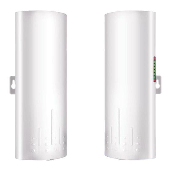
1. Get Started to Know Your Wireless Bridge: Package Included 2 x Outdoor Wireless Bridge 2 x PoE Adapter 2 x Metal Cable Tie 1 X User Manual Note: This wireless bridge is powered by a PoE adapter through a network cable, so does not require a DC power supply. -
Page 4: Cpe Bridge For Video Transmission Introduction
2. CPE Bridge For Video Transmission Introduction: CPE is widely used in highways, reservoir river monitoring, elevator monitoring systems, site crane monitoring systems, port terminal monitoring systems, marine aquaculture monitoring systems and so on. CPE Video Bridge Transmission usually consists of two devices in AP and Client mode respectively. -
Page 5: Connection Diagram
4.Outdoor CPE Specification: Model: CPE450 Master control: AR9344 DRAM: DDR2 64MByte FLASH:8MByte Wired Interface:10/100Mbps LAN*2 CPE Transmission rate: 300Mbps (not network rate) Transfer method: Direct Sequence Spread Spectrum (DSSS) Modulation: OFDM/BPSK/QPSK/CCK/DQPSK/DBPSK Network Standard:IEEE802.11n,IEEE802.11a ,IEEE802.3u Supporting agreement: CSMA/CA TCP/IP,IPX/SPX,NetBEUI,DHCP,NDIS3,N- DIS4,NDIS5 Frequency Range: 4900~6100MHz Power consumption: ≤3W... -
Page 6: Digital Display Wireless Bridge Set Up
5.2. Receiving Side: 6. Digital Display Wireless Bridge Set Up: *It is strongly recommended to pair the wireless bridge in this way. The digital display bridge is simply connected by dialing. After setting Bridge 1 and Bridge 2 to A and B mode, set the two bridges to the same number(1,2,3 ,...,F)... - Page 7 Before connecting the power supply, move the bridge 1 to the A end through the A-B button, and the bridge 2 moves to the B end through the A-B button, the A end represents the receiving mode, the B end represents the transmitting mode;...
-
Page 8: How To Access And Setting The Cpe Via Pc
6.5 LED Number & IP Chart: A IP B IP 2.4G ID 5.8G ID 192.168.255.100 192.168.255.200 192.168.255.101 192.168.255.201 192.168.255.102 192.168.255.202 192.168.255.103 192.168.255.203 192.168.255.104 192.168.255.204 192.168.255.105 192.168.255.205 192.168.255.106 192.168.255.206 192.168.255.107 192.168.255.207 192.168.255.108 192.168.255.208 192.168.255.109 192.168.255.209 192.168.255.110 192.168.255.210 192.168.255.111 192.168.255.211 192.168.255.112 192.168.255.212 192.168.255.113 192.168.255.213 192.168.255.114... - Page 9 Step 3. Find the number of the Wireless Bridge CPE digital display tube. For example, the number is 1 and the CEP is the A master bridge, then the IP of this CPE is 192.168.255.101; if the CPE is the B slave bridge, then the IP address of the CPE is 192.168.255.201.(There is a table corresponding to a number and IP in the manual)...
- Page 10 b. Select Ethernet and Click the Change Adapter Option. c. Find the network connection you are using and right click on Properties. d. Double-click the IPV4 setting, e. Configure your PC IP as select the IP address below, 192.168.255.xxx (xxx is a figure enter the IP and confirm.
-
Page 11: Bridge Configuration (Web Ui)
8.Bridge Configuration (WEB UI) : Note: Before configuring the Bridge IP, AP Configuration, Client Configuration, make sure that the PC and CPE are properly connected and that the PC IP is configured. 8.1 Computer Setup Debug Connection Diagram: 8.2 Configure Bridge IP: Please assign a different IP address to each CPE under the same local area network for easy management. - Page 12 8.3 Wireless Receiver Mode(Receiving Point) Select "A(Master)" under the "Mode", then select Matching ID(Such as "64(5320Mhz)" ),The matching IDs of A(Master) and B(Slave) must be the same. Create an easy-to-remember name for your wireless network in Host- name. See figure below: 8.4 Wireless Transmission Mode(Transmission Point)...
-
Page 13: Field Applications
CPE Connection Diagram: 9. Field Applications: 9.1 Point to Point Connection:... - Page 14 9.2 Point o to t Multi-Point Connection: 9.3 Multiples Clients Connection:...
-
Page 15: Wireless Surveillance Connection For Elevator Well
10.Wireless Surveillance Connection for Elevator Well:... -
Page 16: Tips
Network dingram(3) Point-to-point Wireless Network Coverage Extend the network to warehouses, barns, and garages near your home CPE A CPE B Internet Router Computer Router Router device (AP mode) 11.Tips: 1. The installation of this device requires some network knowledge. If you can't install it, please let us know or contact a professional.
Need help?
Do you have a question about the CPE450 and is the answer not in the manual?
Questions and answers
The user manual password Zllinkcpe12345648 doesn’t work
If the user manual password zllinkcpe12345648 for the UeeVii CPE450 does not work, the following steps should be taken:
1. Re-input the password carefully to ensure there are no typing errors.
2. Confirm that the correct SSID is being used and matches the corresponding password from the WiFi table.
3. Make sure you are not confusing the WiFi password with the WEB access credentials. The WEB access username and password are both "admin".
4. If the password is still not working, refer to the WiFi table in the manual to verify the correct password for the SSID being used.
This answer is automatically generated