ASROCK 990FX Extreme4 Manual
- Quick installation manual (281 pages) ,
- Manual (281 pages) ,
- User manual (70 pages)
Advertisement
- 1 Motherboard Layout
- 2 I/O Panel
- 3 Introduction
-
4
Installation
- 4.1 Pre-installation Precautions
- 4.2 CPU Installation
- 4.3 Installation of CPU Fan and Heatsink
- 4.4 Installation of Memory Modules (DIMM)
- 4.5 Expansion Slots (PCI and PCI Express Slots)
- 4.6 SLITM and Quad SLITM Operation Guide
- 4.7 CrossFireXTM, 3-Way CrossFireXTM and Quad CrossFireXTM Operation Guide
- 4.8 Surround Display Feature
- 4.9 Jumpers Setup
- 4.10 Onboard Headers and Connectors
- 4.11 Smart Switches
- 4.12 Dr. Debug
- 4.13 Driver Installation Guide
- 4.14 Installing Windows 7 / 7 64-bit / VistaTM / VistaTM 64-bit / XP / XP 64-bit With RAID Functions
- 4.15 Installing Windows 7 / 7 64-bit / VistaTM / VistaTM 64-bit / XP / XP 64-bit Without RAID Functions
- 4.16 Untied Overclocking Technology
- 5 BIOS Information
- 6 Software Support CD information
- 7 Documents / Resources
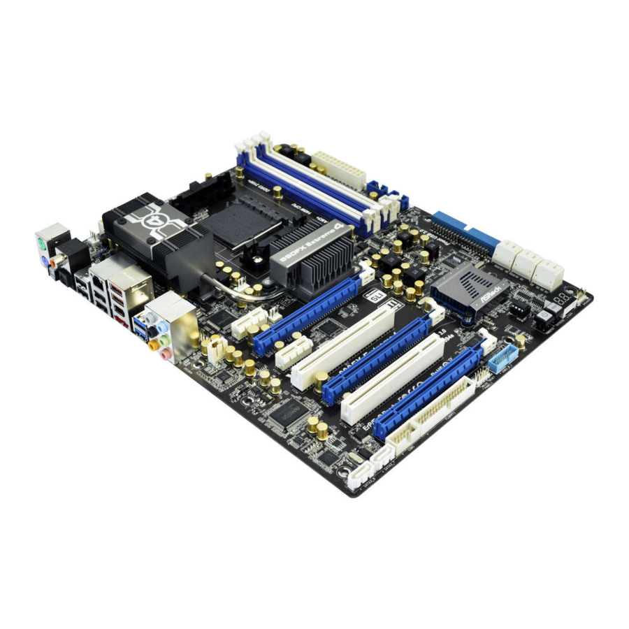
Motherboard Layout

- HDMI_SPDIF Header (HDMI_SPDIF1, White)
- Chassis Fan Connector (CHA_FAN3)
- Clear CMOS Jumper (CLRCMOS1)
- Chassis Fan Connector (CHA_FAN2)
- ATX 12V Power Connector (ATX12V1)
- CPU Fan Connector (CPU_FAN1)
- CPU Fan Connector (CPU_FAN2)
- CPU Heatsink Retention Module
- AM3+ CPU Socket
- 2 x 240-pin DDR3 DIMM Slots (Dual Channel B: DDR3_A1, DDR3_B1; Blue)
- 2 x 240-pin DDR3 DIMM Slots (Dual Channel B: DDR3_A2, DDR3_B2; White)
- ATX Power Connector (ATXPWR1)
- USB 2.0 Header (USB8_9, Blue)
- USB 2.0 Header (USB2_3, Blue)
- Front Panel IEEE 1394 Header (FRONT_1394, White)
- Northbridge Controller
- Southbridge Controller
- Primary IDE Connector (IDE1, Blue)
- SATA3 Connector (SATA3_5_6, White)
- SATA3 Connector (SATA3_3_4, White)
- SATA3 Connector (SATA3_1_2, White)
- Power LED Header (PLED1)
- Chassis Speaker Header (SPEAKER 1, White)
- Dr. Debug (LED)
- Reset Switch (RSTBTN)
- Power Switch (PWRBTN)
- SPI Flash Memory (32Mb)
- USB 3.0 Header (USB3_0_1, Light Blue)
- System Panel Header (PANEL1, White)
- Floppy Connector (FLOPPY1)
- Serial Port Connector (COM1)
- SATA3 Connector (SATA3_7, White)
- SATA3 Connector (SATA3_8, White)
- PCI Express 2.0 x16 Slot (PCIE5; Blue)
- PCI Slot (PCI2)
- PCI Express 2.0 x16 Slot (PCIE4; Blue)
- PCI Slot (PCI1)
- PCI Express 2.0 x1 Slot (PCIE3; White)
- PCI Express 2.0 x16 Slot (PCIE2; Blue)
- Power Fan Connector (PWR_FAN1)
- PCI Express 2.0 x1 Slot (PCIE1; White)
- Internal Audio Connector: CD1 (White)
- Front Panel Audio Header (HD_AUDIO1, White)
- Infrared Module Header (IR1)
- Chassis Fan Connector (CHA_FAN1)
I/O Panel

- PS/2 Mouse Port (Green)
- Coaxial SPDIF Out Port
- * LAN RJ-45 Port
- USB 2.0 Ports (USB45)
- Side Speaker (Gray)
- Rear Speaker (Black)
- Central / Bass (Orange)
- Line In (Light Blue)
- **Front Speaker (Lime)
- Microphone (Pink)
- USB 3.0 Ports (USB23)
- IEEE 1394 Port (IEEE 1394)
- *** eSATA3 Connector
- USB 2.0 Ports (USB67)
- USB 2.0 Ports (USB01)
- Optical SPDIF Out Port
- Clear CMOS Switch (CLRCBTN)
- PS/2 Keyboard Port (Purple)
* There are two LED next to the LAN port. Please refer to the table below for the LAN port LED indications.
LAN Port LED Indications

Activity/Link LED
| Status | Description |
| Off | No Link |
| Blinking | Data Activity |
| On | Link |
SPEED LED
| Status | Description |
| Off | 10Mbps connection |
| Orange | 100Mbps connection |
| Green | 1Gbps connection |
** If you use 2-channel speaker, please connect the speaker's plug into "Front Speaker Jack".
See the table below for connection details in accordance with the type of speaker you use.
TABLE for Audio Output Connection
| Audio Output Channels | Front Speaker (No. 9) | Rear Speaker (No. 6) | Central / Bass (No. 7) | Side Speaker (No. 5) | |
| 2 | V | -- | -- | -- | |
| 4 | V | V | -- | -- | |
| 6 | V | V | V | -- | |
| 8 | V | V | V | V | |
To enable Multi-Streaming function, you need to connect a front panel audio cable to the front panel audio header. After restarting your computer, you will find "Mixer" tool on your system. Please select "Mixer ToolBox" ![]() , click "Enable playback multi-streaming", and click "ok".
, click "Enable playback multi-streaming", and click "ok".
Choose "2CH", "4CH", "6CH", or "8CH" and then you are allowed to select "Realtek HDA Primary output" to use Rear Speaker, Central/Bass, and Front Speaker, or select "Realtek HDA Audio 2nd output" to use front panel audio.
*** eSATA3 connector supports SATA Gen3 in cable 1M.
Introduction
Thank you for purchasing ASRock 990FX Extreme4 motherboard, a reliable motherboard produced under ASRock's consistently stringent quality control. It delivers excellent performance with robust design conforming to ASRock's commitment to quality and endurance.
In this manual, chapter 1 and 2 contain introduction of the motherboard and stepby-step guide to the hardware installation. Chapter 3 and 4 contain the configuration guide to BIOS setup and information of the Support CD.
 Because the motherboard specifications and the BIOS software might be updated, the content of this manual will be subject to change without notice. In case any modifications of this manual occur, the updated version will be available on ASRock website without further notice. You may find the latest VGA cards and CPU support lists on ASRock website as well. ASRock website
http://www.asrock.com
If you require technical support related to this motherboard, please visit our website for specific information about the model you are using.
www.asrock.com/support/index.asp
Package Contents
ASRock 990FX Extreme4 Motherboard (ATX Form Factor: 12.0-in x 9.6-in, 30.5 cm x 24.4 cm)
ASRock 990FX Extreme4 Quick Installation Guide
ASRock 990FX Extreme4 Support CD
1 x ASRock SLI_Bridge_2S Card
1 x 80-conductor Ultra ATA 66/100/133 IDE Ribbon Cable
1 x Ribbon Cable for a 3.5-in Floppy Drive
4 x Serial ATA (SATA) Data Cables (Optional)
2 x Serial ATA (SATA) HDD Power Cables (Optional)
1 x 3.5mm Audio Cable (Optional)
1 x I/O Panel Shield
1 x Front USB 3.0 Panel
4 x HDD Screws
6 x Chassis Screws
1 x Rear USB 3.0 Bracket

ASRock Reminds You...
To get better performance in Windows® 7 / 7 64-bit / VistaTM / VistaTM 64 bit, it is recommended to set the BIOS option in Storage Configuration to AHCI mode. For the BIOS setup, please refer to the "User Manual" in our support CD for details.
Specifications
| Platform |
|
| CPU |
|
| Chipset |
|
| Memory |
|
| Expansion Slot |
|
| Audio |
|
| LAN |
|
| Rear Panel I/O | I/O Panel
|
| SATA3 |
|
| USB 3.0 |
|
| Connector |
|
| Smart Switch |
|
| BIOS Feature |
|
| Support CD |
|
| Unique Feature |
|
| Hardware Monitor |
|
| OS |
|
| Certifications |
|
* For detailed product information, please visit our website: http://www.asrock.com

Please realize that there is a certain risk involved with overclocking, including adjusting the setting in the BIOS, applying Untied Overclocking Technology, or using the third-party overclocking tools. Overclocking may affect your system stability, or even cause damage to the components and devices of your system. It should be done at your own risk and expense.
We are not responsible for possible damage caused by overclocking.

- ASRock UCC (Unlock CPU Core) feature simplifies AMD CPU activation. As long as a simple switch of the UEfioption "ASRock UCC", you can unlock the extra CPU core to enjoy an instant performance boost. When UCC feature is enabled, the dual-core or triple-core CPU will boost to the quad-core CPU, and some CPU, including quad-core CPU, can also increase L3 cache size up to 6MB, which means you can enjoy the upgrade CPU performance with a better price. Please be noted that UCC feature is supported with AM3 CPU only, and in addition, not every AM3 CPU can support this function because some CPU's hidden core may be malfunctioned.
- This motherboard supports Untied Overclocking Technology. Please read "Untied Overclocking Technology" for details.
- This motherboard supports Dual Channel Memory Technology. Before you implement Dual Channel Memory Technology, make sure to read the installation guide of memory modules for proper installation.
- Whether 2100MHz memory speed is supported depends on the AM3/ AM3+ CPU you adopt. If you want to adopt DDR3 2100 memory module on this motherboard, please refer to the memory support list on our website for the compatible memory modules.
ASRock website http://www.asrock.com - Due to the operating system limitation, the actual memory size may be less than 4GB for the reservation for system usage under Windows® 7 / VistaTM / XP. For Windows® 64-bit OS with 64-bit CPU, there is no such limitation.
- For microphone input, this motherboard supports both stereo and mono modes. For audio output, this motherboard supports 2-channel, 4-channel, 6-channel, and 8-channel modes. Please check the table for proper connection.
- ASRock Extreme Tuning Utility (AXTU) is an all-in-one tool to ne-tune different system functions in a user-friendly interface, which is including Hardware Monitor, Fan Control, Overclocking, OC DNA and IES. In Hardware Monitor, it shows the major readings of your system. In Fan Control, it shows the fan speed and temperature for you to adjust. In Overclocking, you are allowed to overclock CPU frequency for optimal system performance. In OC DNA, you can save your OC settings as a profile and share with your friends. Your friends then can load the OC profile to their own system to get the same OC settings. In IES (Intelligent Energy Saver), the voltage regulator can reduce the number of output phases to improve efficiency when the CPU cores are idle without sacrificing computing performance. Please visit our website for the operation procedures of ASRock Extreme Tuning Utility (AXTU).
ASRock website: http://www.asrock.com - ASRock Instant Flash is a BIOS flash utility embedded in Flash ROM. This convenient BIOS update tool allows you to update system BIOS without entering operating systems first like MS-DOS or Windows®. With this utility, you can press <F6> key during the POST or press <F2> key to BIOS setup menu to access ASRock Instant Flash. Just launch this tool and save the new BIOS file to your USB flash drive, floppy disk or hard drive, then you can update your BIOS only in a few clicks without preparing an additional floppy diskette or other complicated flash utility. Please be noted that the USB flash drive or hard drive must use FAT32/16/12 file system.
- If you desire a faster, less restricted way of charging your Apple devices, such as iPhone/iPod/iPad Touch, ASRock has prepared a wonderful solution for you - ASRock APP Charger. Simply installing the APP Charger driver, it makes your iPhone charged much quickly from your computer and up to 40% faster than before. ASRock APP Charger allows you to quickly charge many Apple devices simultaneously and even supports continuous charging when your PC enters into Standby mode (S1), Suspend to RAM (S3), hibernation mode (S4) or power off (S5). With APP Charger driver installed, you can easily enjoy the marvelous charging experience than ever. ASRock website: http://www.asrock.com/Feature/AppCharger/index.asp
- ASRock XFast USB can boost USB storage device performance. The performance may depend on the property of the device.
- ASRock On/Off Play Technology allows users to enjoy the great audio experience from the portable audio devices, such like MP3 player or mobile phone to your PC, even when the PC is turned off (or in ACPI S5 mode)! This motherboard also provides a free 3.5mm audio cable (optional) that ensures users the most convenient computing environment.
- Although this motherboard offers stepless control, it is not recommended to perform over-clocking. Frequencies other than the recommended CPU bus frequencies may cause the instability of the system or damage the CPU.
- While CPU overheat is detected, the system will automatically shutdown. Before you resume the system, please check if the CPU fan on the motherboard functions properly and unplug the power cord, then plug it back again. To improve heat dissipation, remember to spray thermal grease between the CPU and the heatsink when you install the PC system.
- EuP, stands for Energy Using Product, was a provision regulated by European Union to define the power consumption for the completed system. According to EuP, the total AC power of the completed system shall be under 1.00W in off mode condition. To meet EuP standard, an EuP ready motherboard and an EuP ready power supply are required. According to Intel's suggestion, the EuP ready power supply must meet the standard of 5v standby power efficiency is higher than 50% under 100 mA current consumption. For EuP ready power supply selection, we recommend you checking with the power supply manufacturer for more details.
Installation
This is an ATX form factor (12.0-in x 9.6-in, 30.5 cm x 24.4 cm) motherboard. Before you install the motherboard, study the configuration of your chassis to ensure that the motherboard fits into it.
Pre-installation Precautions
Take note of the following precautions before you install motherboard components or change any motherboard settings.
Before you install or remove any component, ensure that the power is switched off or the power cord is detached from the power supply. Failure to do so may cause severe damage to the motherboard, peripherals, and/or components.
- Unplug the power cord from the wall socket before touching any component.
- To avoid damaging the motherboard components due to static electricity, NEVER place your motherboard directly on the carpet or the like. Also remember to use a grounded wrist strap or touch a safety grounded object before you handle components.
- Hold components by the edges and do not touch the ICs.
- Whenever you uninstall any component, place it on a grounded antistatic pad or in the bag that comes with the component.
- When placing screws into the screw holes to secure the motherboard to the chassis, please do not over-tighten the screws! Doing so may damage the motherboard.
CPU Installation
Step 1. Unlock the socket by lifting the lever up to a 90o angle.

Lift Up The Socket Lever
Step 2. Position the CPU directly above the socket such that the CPU corner with the golden triangle matches the socket corner with a small triangle.
Step 3. Carefully insert the CPU into the socket until it fits in place.

2&3: Match The CPU Golden Triangle To The Socket Corner Small Triangle
The CPU firts only in one correct orientation. DO NOT force the CPU into the socket to avoid bending of the pins.
Step 4. When the CPU is in place, press it firmly on the socket while you push down the socket lever to secure the CPU. The lever clicks on the side tab to indicate that it is locked.

Push Down And Lock The Socket Lever
Installation of CPU Fan and Heatsink
After you install the CPU into this motherboard, it is necessary to install a larger heatsink and cooling fan to dissipate heat. You also need to spray thermal grease between the CPU and the heatsink to improve heat dissipation. Make sure that the CPU and the heatsink are securely fastened and in good contact with each other. Then connect the CPU fan to the CPU FAN connector (CPU_FAN1, see "Motherboard Layout", No. 6 or CPU_FAN2, see "Motherboard Layout", No. 7). For proper installation, please kindly refer to the instruction manuals of the CPU fan and the heatsink.
Installation of Memory Modules (DIMM)
This motherboard provides four 240-pin DDR3 (Double Data Rate 3) DIMM slots, and supports Dual Channel Memory Technology. For dual channel configuration, you always need to install identical (the same brand, speed, size and chip-type) DDR3 DIMM pair in the slots of the same color. In other words, you have to install identical DDR3 DIMM pair in Dual Channel A (DDR3_A1 and DDR3_B1; Blue slots; see "Motherboard Layout", No.10) or identical DDR3 DIMM pair in Dual Channel B (DDR3_ A2 and DDR3_B2; White slots; see "Motherboard Layout", No.11), so that Dual Channel Memory Technology can be activated. This motherboard also allows you to install four DDR3 DIMMs for dual channel configuration, and please install identical DDR3 DIMMs in all four slots. You may refer to the Dual Channel Memory Configuration Table below.
Dual Channel Memory Configurations
| DDR3_A1 (Blue Slot) | DDR3_A2 (White Slot) | DDR3_B1 (Blue Slot) | DDR3_B2 (White Slot) | |
| (1) | Populated | - | Populated | - |
| (2) | - | Populated | - | Populated |
| (3)* | Populated | Populated | Populated | Populated |
* For the configuration (3), please install identical DDR3 DIMMs in all four slots.
- Please install the memory module into the white slot (DDR3_A2 and DDR3_B2) for the first priority.
- If you want to install two memory modules, for optimal compatibility and reliability, it is recommended to install them in the slots of the same color. In other words, install them either in the set of blue slots (DDR3_A1 and DDR3_B1), or in the set of white slots (DDR3_ A2 and DDR3_B2).
- If only one memory module or three memory modules are installed in the DDR3 DIMM slots on this motherboard, it is unable to activate the Dual Channel Memory Technology.
- If a pair of memory modules is NOT installed in the same Dual Channel, for example, installing a pair of memory modules in DDR3_A1 and DDR3_A2, it is unable to activate the Dual Channel Memory Technology.
- It is not allowed to install a DDR or DDR2 memory module into DDR3 slot; otherwise, this motherboard and DIMM may be damaged.
- If you adopt DDR3 2100 memory modules on this motherboard, it is recommended to install them on DDR3_A2 and DDR3_B2 slots.
Installing a DIMM
Please make sure to disconnect power supply before adding or removing DIMMs or the system components.
Step 1. Unlock a DIMM slot by pressing the retaining clips outward.
Step 2. Align a DIMM on the slot such that the notch on the DIMM matches the break on the slot.

The DIMM only fits in one correct orientation. It will cause permanent damage to the motherboard and the DIMM if you force the DIMM into the slot at incorrect orientation.
Step 3. Firmly insert the DIMM into the slot until the retaining clips at both ends fully snap back in place and the DIMM is properly seated.
Expansion Slots (PCI and PCI Express Slots)
There are 2 PCI slots and 5 PCI Express slots on this motherboard.
PCI Slots:
PCI slots are used to install expansion cards that have the 32-bit PCI interface.
PCIE Slots:
PCIE1 / PCIE3 (PCIE x1 slot; White) is used for PCI Express cards with x1 lane width cards, such as Gigabit LAN card and SATA2 card. PCIE2 / PCIE4 (PCIE x16 slot; Blue) is used for PCI Express x16 lane width graphics cards, or used to install PCI Express graphics cards to TM TM support SLI and CrossFireX function. PCIE5 (PCIE x16 slot; Blue) is used for PCI Express x4 lane width cards, or used to install PCI Express graphics cards to support 3-Way TM CrossFireX function.
- In single VGA card mode, it is recommended to install a PCI Express x16 graphics card on PCIE2 slot. TM TM
- In CrossFireX or SLI mode, please install PCI Express x16 graphics cards on PCIE2 and PCIE4 slots. Therefore, both these two slots will work at x16 bandwidth. TM
- In 3-Way CrossFireX mode, please install PCI Express x16 graphics cards on PCIE2, PCIE4 and PCIE5 slots. Therefore, PCIE2 and PCIE4 slots will work at x16 bandwidth while PCIE5 slot will work at x4 bandwidth.
- Please connect a chassis fan to motherboard chassis fan connector (CHA_FAN1, CHA_FAN2 or CHA_FAN3) when using multiple graphics cards for better thermal environment.
Installing an expansion card
Step 1. Before installing the expansion card, please make sure that the power supply is switched off or the power cord is unplugged. Please read the documentation of the expansion card and make necessary hardware settings for the card before you start the installation.
Step 2. Remove the system unit cover (if your motherboard is already installed in a chassis).
Step 3. Remove the bracket facing the slot that you intend to use. Keep the screws for later use.
Step 4. Align the card connector with the slot and press firmly until the card is completely seated on the slot.
Step 5. Fasten the card to the chassis with screws.
Step 6. Replace the system cover.
SLITM and Quad SLITM Operation Guide
This motherboard supports NVIDIA® SLITM and Quad SLITM (Scalable Link Interface) technology that allows you to install up to three identical PCI Express x16 graphics cards. Currently, NVIDIA® SLITM technology supports Windows® XP / XP 64-bit / VistaTM / VistaTM 64-bit / 7 / 7 64-bit OS. NVIDIA® Quad SLITM technology support Windows® VistaTM / VistaTM 64-bit / 7 / 7 64-bit OS only. Please follow the installation procedures in this section.
Requirements
- For SLITM technology, you should have two identical SLITM-ready graphics cards that are NVIDIA® certified. For Quad SLITM technology, you should have two identical Quad SLITM-ready graphics cards that are NVIDIA® certified.
- Make sure that your graphics card driver supports NVIDIA® SLITM technology. Download the driver from NVIDIA® website (www.nvidia.com);
- Make sure that your power supply unit (PSU) can provide at least the minimum power required by your system. It is recommended to use NVIDIA® certified PSU. Please refer to NVIDIA® website for details.
Graphics Card Setup
Installing Two SLITM-Ready Graphics Cards
Step 1. Install the identical SLITM-ready graphics cards that are NVIDIA® certified because different types of graphics cards will not work together properly. (Even the GPU chips version shall be the same.) Insert one graphics card into PCIE2 slot and the other graphics card to PCIE4 slot. Make sure that the cards are properly seated on the slots.

Step 2. If required, connect the auxiliary power source to the PCI Express graphics cards.
Step 3. Align and insert ASRock SLI_Bridge_2S Card to the goldfingers on each graphics card. Make sure ASRock SLI_Bridge_2S Card is firmly in place.

Step 4. Connect a VGA cable or a DVI cable to the monitor connector or the DVI connector of the graphics card that is inserted to PCIE2 slot.
Driver Installation and Setup
Install the graphics card drivers to your system. After that, you can enable the MultiGraphics Processing Unit (GPU) feature in the NVIDIA® nView system tray utility. Please follow the below procedures to enable the multi-GPU feature.
For Windows® XP / XP 64-bit OS:
(For SLITM mode only)
- Double-click NVIDIA Settings icon on your Windows® taskbar.
![]()
- From the pop-up menu, select Set SLI and PhysX configuration. In Set PhysX GPU acceleration item, please select Enabled. In Select an SLI configuration item, please select Enable SLI. And click Apply.
![]()
- Reboot your system.
- You can freely enjoy the benefit of SLITM feature.


For Windows® VistaTM / VistaTM 64-bit / 7 / 7 64-bit OS:
(For SLITM and Quad SLITM mode)
- Click the Start icon on your Windows taskbar.
- From the pop-up menu, select All Programs, and then click NVIDIA Corporation.
- Select NVIDIA Control Panel tab.
- Select Control Panel tab.
![]()
- From the pop-up menu, select Set SLI and PhysX configuration. In Set PhysX GPU acceleration item, please select Enabled. In Select an SLI configuration item, please select Enable SLI. And click Apply.

- Reboot your system.
- You can freely enjoy the benefit of SLITM or Quad SLITM feature.


* SLITM appearing here is a registered trademark of NVIDIA® Technologies Inc., and is used only for identification or explanation and to the owners' benefit, without intent to infringe.
CrossFireXTM, 3-Way CrossFireXTM and Quad CrossFireXTM Operation Guide
This motherboard supports CrossFireXTM, 3-way CrossFireXTM and Quad CrossFireXTM feature. CrossFireXTM technology offers the most advantageous means available of combining multiple high performance Graphics Processing Units (GPU) in a single PC. Combining a range of different operating modes with intelligent software design and an innovative interconnect mechanism, CrossFireXTM enables the highest possible level of performance and image quality in any 3D application. Currently CrossFireXTM feature is supported with Windows® XP with Service Pack 2 / VistaTM / 7 OS. 3-way CrossFireXTM and Quad CrossFireXTM feature are supported with Windows® VistaTM / 7 OS only. Please check AMD website for AMDTM CrossFireXTM driver updates.
- If a customer incorrectly configures their system they will not see the performance benefits of CrossFireXTM. All three CrossFireXTM components, a CrossFireXTM Ready graphics card, a CrossFireXTM Ready motherboard and a CrossFireXTM Edition co-processor graphics card, must be installed correctly to benefit from the CrossFireXTM multi-GPU platform.
- If you pair a 12-pipe CrossFireXTM Edition card with a 16-pipe card, both cards will operate as 12-pipe cards while in CrossFireXTM mode.
Graphics Card Setup
Installing Two CrossFireXTM-Ready Graphics Cards
Different CrossFireXTM cards may require different methods to enable CrossFireXTM feature. In below procedures, we use Radeon HD 3870 as the example graphics card. For other CrossFireXTM cards that AMDTM has released or will release in the future, please refer to AMDTM graphics card manuals for detailed installation guide.
Step 1. Insert one Radeon graphics card into PCIE2 slot and the other Radeon graphics card to PCIE4 slot. Make sure that the cards are properly seated on the slots.

Step 2. Connect two Radeon graphics cards by installing CrossFire Bridge on CrossFire Bridge Interconnects on the top of Radeon graphics cards. (CrossFire Bridge is provided with the graphics card you purchase, not bundled with this motherboard. Please refer to your graphics card vendor for details.)

Step 3. Connect the DVI monitor cable to the DVI connector on the Radeon graphics card on PCIE2 slot. (You may use the DVI to D-Sub adapter to convert the DVI connector to D-Sub interface, and then connect the D-Sub monitor cable to the DVI to D-Sub adapter.)
Installing Three CrossFireXTM-Ready Graphics Cards
Step 1. Install one Radeon graphics card to PCIE2 slot. For the proper installation procedures, please refer to section "Expansion Slots".

Step 2. Install one Radeon graphics card to PCIE4 slot. For the proper installation procedures, please refer to section "Expansion Slots".

Step 3. Install one Radeon graphics card to PCIE5 slot. For the proper installation procedures, please refer to section "Expansion Slots".

Step 4. Use one CrossFireTM Bridge to connect Radeon graphics cards on PCIE2 and PCIE4 slots, and use the other CrossFireTM Bridge to connect Radeon graphics cards on PCIE4 and PCIE5 slots. (CrossFireTM Bridge is provided with the graphics card you purchase, not bundled with this motherboard. Please refer to your graphics card vendor for details.)

Step 5. Connect the DVI monitor cable to the DVI connector on the Radeon graphics card on PCIE2 slot. (You may use the DVI to D-Sub adapter to convert the DVI connector to D-Sub interface, and then connect the D-Sub monitor cable to the DVI to D-Sub adapter.)

Driver Installation and Setup
Step 1. Power on your computer and boot into OS.
Step 2. Remove the ATITM driver if you have any VGA driver installed in your system.
The Catalyst Uninstaller is an optional download. We recommend using this utility to uninstall any previously installed Catalyst drivers prior to installation. Please check AMD website for ATITM driver updates.
Step 3. Install the required drivers to your system.
For Windows® XP OS:
- AMDTM recommends Windows® XP Service Pack 2 or higher to be installed (If you have Windows® XP Service Pack 2 or higher installed in your system, there is no need to download it again):
http://www.microsoft.com/windowsxp/sp2/default.mspx - You must have Microsoft. NET Framework installed prior to downloading and installing the CATALYST Control Center. Please check Microsoft website for details.
For Windows® 7 / VistaTM OS:
Install the CATALYST Control Center. Please check AMD website for details.
Step 4. Restart your computer.
Step 5. Install the VGA card drivers to your system, and restart your computer.
Then you will find "ATI Catalyst Control Center" on your Windows® taskbar.

ATI Catalyst Control Center
Step 6. Double-click "ATI Catalyst Control Center". Click "View", select "CrossFireXTM", and then check the item "Enable CrossFireXTM". Select "2 GPUs" and click "Apply" (if you install two Radeon graphics cards). Select "3 GPUs" and click "OK" (if you install three Radeon graphics cards).

Although you have selected the option "Enable CrossFireTM", the CrossFireXTM function may not work actually. Your computer will automatically reboot. After restarting your computer, please confirm whether the option "Enable CrossFireTM" in "ATI Catalyst Control Center" is selected or not; if not, please select it again, and then you are able to enjoy the benefit of CrossFireXTM feature.
Step 7. You can freely enjoy the benefit of CrossFireXTM, 3-Way CrossFireXTM or Quad CrossFireXTM feature.
* CrossFireXTM appearing here is a registered trademark of AMDTM Technologies Inc., and is used only for identification or explanation and to the owners' benefit, without intent to infringe.
* For further information of AMDTM CrossFireXTM technology, please check AMD website for updates and details.
Surround Display Feature
This motherboard supports Surround Display upgrade. With the external add-on PCI Express VGA cards, you can easily enjoy the benefits of Surround Display feature. For the detailed instruction, please refer to the document at the following path in the Support CD:
..\ Surround Display Information
Jumpers Setup
The illustration shows how jumpers are setup. When the jumper cap is placed on pins, the jumper is "Short". If no jumper cap is placed on pins, the jumper is "Open". The illustration shows a 3-pin jumper whose pin1 and pin2 are "Short" when jumper cap is placed on these 2 pins.

| Jumper | Setting | Description |
| Clear CMOS Jumper (CLRCMOS1) (see "Motherboard Layout" No. 3) |  |  |
 Note: CLRCMOS1 allows you to clear the data in CMOS. To clear and reset the system parameters to default setup, please turn off the computer and unplug the power cord from the power supply. After waiting for 15 seconds, use a jumper cap to short pin2 and pin3 on CLRCMOS1 for 5 seconds. However, please do not clear the CMOS right after you update the BIOS. If you need to clear the CMOS when you just finish updating the BIOS, you must boot up the system first, and then shut it down before you do the clear-CMOS action. Please be noted that the password, date, time, user default profile, 1394 GUID and MAC address will be cleared only if the CMOS battery is removed.
The Clear CMOS Switch has the same function as the Clear CMOS jumper.
Onboard Headers and Connectors
Onboard headers and connectors are NOT jumpers. Do NOT place jumper caps over these headers and connectors. Placing jumper caps over the headers and connectors will cause permanent damage of the motherboard!
| FDD connector (33-pin FLOPPY1) (see "Motherboard Layout" No. 30) |  |  |
Note: Make sure the red-striped side of the cable is plugged into Pin1 side of the connector.
Primary IDE connector (Blue)
(39-pin IDE1, see "Motherboard Layout" No. 18)

Note: Please refer to the instruction of your IDE device vendor for the details.
Serial ATA (SATA) Data Cable (Optional)

Either end of the SATA data cable can be connected to the SATA3 hard disk or the SATA3 connector on this motherboard.
3.5mm Audio Cable (Optional)

Either end of the 3.5mm audio cable can be connected to the portable audio devices, such as MP3 player and mobile phone or the Line-in port of your PC.
Serial ATA (SATA) Power Cable (Optional)

Please connect the black end of SATA power cable to the power connector on each drive. Then connect the white end of SATA power cable to the power connector of the power supply.
Serial ATA3 Connectors
(SATA3_1_2: see "Motherboard Layout", No. 21)
(SATA3_3_4: see "Motherboard Layout", No. 20)
(SATA3_5_6: see "Motherboard Layout", No. 19)
(SATA3_7:see "Motherboard Layout", No. 32)
(SATA3_8:see "Motherboard Layout", No. 33)

These eight Serial ATA3
(SATA3) connectors support SATA data cables for internal storage devices. The current SATA3 interface allows up to 6.0 Gb/s data transfer rate. If you install the HDD on the eSATA port on the rear I/O, the internal SATA3_8 will not function.
USB 2.0 Headers
(9-pin USB2_3) (see "Motherboard Layout", No. 14)

Besides six default USB 2.0 ports on the I/O panel, there are two USB 2.0 headers on this motherboard. Each USB 2.0 header can support two USB 2.0 ports.
USB 3.0 Header
(19-pin USB3_0_1) (see"Motherboard Layout", No. 28)

Besides two default USB 3.0 ports on the I/O panel, there is one USB 3.0 header on this motherboard. This USB 3.0 header can support two USB 3.0 ports.
Infrared Module Header
(5-pin IR1) (see "Motherboard Layout", No. 44)

This header supports an optional wireless transmitting and receiving infrared module.
Internal Audio Connectors
(4-pin CD1) (CD1: see "Motherboard Layout", No. 42)

This connector allows you to receive stereo audio input from sound sources such as a CD-ROM, DVD-ROM, TV tuner card, or MPEG card.
Front Panel Audio Header
(9-pin HD_AUDIO1) (see "Motherboard Layout", No. 43)

This is an interface for the front panel audio cable that allows convenient connection and control of audio devices.
- High Definition Audio supports Jack Sensing, but the panel wire on the chassis must support HDA to function correctly. Please follow the instruction in our manual and chassis manual to install your system.
- If you use AC'97 audio panel, please install it to the front panel audio header as below:
- Connect Mic_IN (MIC) to MIC2_L.
- Connect Audio_R (RIN) to OUT2_R and Audio_L (LIN) to OUT2_L.
- Connect Ground (GND) to Ground (GND).
- MIC_RET and OUT_RET are for HD audio panel only. You don't need to connect them for AC'97 audio panel.
- To activate the front mic. ® For Windows XP / XP 64-bit OS: Select "Mixer". Select "Recorder". Then click "FrontMic". ® TM TM For Windows 7 / 7 64-bit / Vista / Vista 64-bit OS: Go to the "FrontMic" Tab in the Realtek Control panel. Adjust "Recording Volume".
System Panel Header
(9-pin PANEL1) (see "Motherboard Layout", No. 29)

This header accommodates several system front panel functions.
Connect the power switch, reset switch and system status indicator on the chassis to this header according to the pin assignments below.
Note the positive and negative pins before connecting the cables.
PWRBTN (Power Switch):
Connect to the power switch on the chassis front panel. You may configure the way to turn off your system using the power switch.
RESET (Reset Switch):
Connect to the reset switch on the chassis front panel. Press the reset switch to restart the computer if the computer freezes and fails to perform a normal restart.
PLED (System Power LED):
Connect to the power status indicator on the chassis front panel. The LED is on when the system is operating. The LED keeps blinking when the system is in S1 sleep state. The LED is off when the system is in S3/S4 sleep state or powered off (S5).
HDLED (Hard Drive Activity LED):
Connect to the hard drive activity LED on the chassis front panel. The LED is on when the hard drive is reading or writing data.
The front panel design may differ by chassis. A front panel module mainly consists of power switch, reset switch, power LED, hard drive activity LED, speaker and etc. When connecting your chassis front panel module to this header, make sure the wire assignments and the pin assignments are matched correctly.
Chassis Speaker Header
(4-pin SPEAKER 1) (see "Motherboard Layout", No.23)

Please connect the chassis speaker to this header.
Power LED Header
(3-pin PLED1) (see "Motherboard Layout", No. 22)

Please connect the chassis power LED to this header to indicate system power status. The LED is on when the system is operating. The LED keeps blinking in S1 state. The LED is off in S3/S4 state or S5 state (power off).
Chassis and Power Fan Connectors
(4-pin CHA_FAN1) (see "Motherboard Layout", No. 45)

(3-pin CHA_FAN2) (see "Motherboard Layout", No. 4)

(3-pin CHA_FAN3) (see "Motherboard Layout", No. 2)

(3-pin PWR_FAN1) (see "Motherboard Layout", No. 40)

CPU Fan Connectors
(4-pin CPU_FAN1) (see "Motherboard Layout", No. 6)

Please connect the CPU fan cable to the connector and match the black wire to the ground pin.
Though this motherboard provides 4-Pin CPU fan (Quiet Fan) support, the 3-Pin CPU fan still can work successfully even without the fan speed control function. If you plan to connect the 3-Pin CPU fan to the CPU fan connector on this motherboard, please connect it to Pin 1-3.

(3-pin CPU_FAN2)
(see "Motherboard Layout", No. 7)

ATX Power Connector
(24-pin ATXPWR1) (see "Motherboard Layout", No. 12)

Please connect an ATX power supply to this connector.
Though this motherboard provides 24-pin ATX power connector, it can still work if you adopt a traditional 20-pin ATX power supply. To use the 20-pin ATX power supply, please plug your power supply along with Pin 1 and Pin 13.
20-Pin ATX Power Supply Installation

ATX 12V Power Connector
(8-pin ATX12V1) (see "Motherboard Layout", No. 5)

Please connect an ATX 12V power supply to this connector.
Though this motherboard provides 8-pin ATX 12V power connector, it can still work if you adopt a traditional 4-pin ATX 12V power supply. To use the 4-pin ATX power supply, please plug your power supply along with Pin 1 and Pin 5.
4-Pin ATX 12V Power Supply Installation

IEEE 1394 Header
(9-pin FRONT_1394) (see "Motherboard Layout", No. 15)

Besides one default IEEE 1394 port on the I/O panel, there is one IEEE 1394 header (FRONT_1394) on this motherboard. This IEEE 1394 header can support one IEEE 1394 port.
Serial port Header
(9-pin COM1) (see "Motherboard Layout", No.31)

This COM1 header supports a serial port module.
HDMI_SPDIF Header
(2-pin HDMI_SPDIF1) ( see "Motherboard Layout", No. 1)

HDMI_SPDIF header, providing SPDIF audio output to HDMI VGA card, allows the system to connect HDMI Digital TV/ projector/LCD devices. Please connect the HDMI_SPDIF connector of HDMI VGA card to this header.
Front USB 3.0 Panel Installation Guide
Step 1 Prepare the bundled Front USB 3.0 Panel, four HDD screws, and six chassis screws.

Step 2 Screw the 2.5" HDD/SSD to the Front USB 3.0 Panel with four HDD screws.

Step 3 Install the Front USB 3.0 Panel into the 2.5" drive bay of the chassis.

Step 4 Screw the Front USB 3.0 Panel to the drive bay with six chassis screws.

Step 5 Plug the Front USB 3.0 cable into the USB 3.0 header (USB3_0_1) on the motherboard.

Step 6 The Front USB 3.0 Panel is ready to use.

Rear USB 3.0 Bracket Installation Guide
Step 1 Unscrew the two screws from the Front USB 3.0 Panel.

Step 2 Put the USB 3.0 cable and the rear USB 3.0 bracket together.

Step 3 Screw the two screws into the rear USB 3.0 bracket.

Step 4 Put the rear USB 3.0 bracket into the chassis.

Smart Switches
This motherboard has three smart switches: power switch, reset switch and clear CMOS switch, allowing users to quickly turn on/off or reset the system or clear the CMOS values.
| Power Switch (PWRBTN) (see "Motherboard Layout", No. 26) |  | Power Switch is a smart switch, allowing users to quickly turn on/off the system. |
| Reset Switch (RSTBTN) (see "Motherboard Layout", No. 25) |  | Reset Switch is a smart switch, allowing users to quickly reset the system. |
| Clear CMOS Switch (CLRCBTN) (see "I/O Panel", No. 17) |  | Clear CMOS Switch is a smart switch, allowing users to quickly clear the CMOS values |
Dr. Debug
Dr. Debug is used to provide code information, which makes troubleshooting even easier. Please see the diagrams below for reading the Dr. Debug codes.


Driver Installation Guide
To install the drivers to your system, please insert the support CD to your optical drive first. Then, the drivers compatible to your system can be auto-detected and listed on the support CD driver page. Please follow the order from up to bottom side to install those required drivers. Therefore, the drivers you install can work properly.
Installing Windows® 7 / 7 64-bit / VistaTM / VistaTM 64-bit / XP / XP 64-bit With RAID Functions
If you want to install Windows® 7 / 7 64-bit / VistaTM / VistaTM 64-bit / XP / XP 64bit on your SATA3 HDDs with RAID functions, please refer to the document at the following path in the Support CD for detailed procedures:
..\ RAID Installation Guide
Installing Windows® 7 / 7 64-bit / VistaTM / VistaTM 64-bit / XP / XP 64-bit Without RAID Functions
If you want to install Windows® 7 / 7 64-bit / VistaTM / VistaTM 64-bit / XP / XP 64-bit OS on your SATA3 HDDs without RAID functions, please follow below procedures according to the OS you install.
Installing Windows® XP / XP 64-bit Without RAID Functions
If you want to install Windows® XP / XP 64-bit on your SATA3 HDDs without RAID functions, please follow below steps.
Using SATA3 HDDs without NCQ and Hot Plug functions (IDE mode)
STEP 1: Set up UEFI.
- Enter UEFI SETUP UTILITY → Advanced screen → Storage Configuration.
- Set the option "SATA Mode" to [IDE]. (For SATA3_1 to SATA3_6 ports.)
Set the option "Marvell SATA3 Operation Mode" to [IDE]. (For SATA3_7 and SATA3_8 ports.)
STEP 2: Install Windows® XP / XP 64-bit OS on your system.
Installing Windows® 7 / 7 64-bit / VistaTM / VistaTM 64-bit Without RAID Functions
If you want to install Windows® 7 / 7 64-bit / VistaTM / VistaTM 64-bit on your SATA3 HDDs without RAID functions, please follow below steps.
Using SATA3 HDDs without NCQ and Hot Plug functions (IDE mode)
STEP 1: Set up UEFI.
- Enter UEFI SETUP UTILITY → Advanced screen → Storage Configuration.
- Set the option "SATA Mode" to [IDE]. (For SATA3_1 to SATA3_6 ports.)
Set the option "Marvell SATA3 Operation Mode" to [IDE]. (For SATA3_7 and SATA3_8 ports.)
STEP 2: Install Windows® 7 / 7 64-bit / VistaTM / VistaTM 64-bit OS on your system.
Using SATA3 HDDs with NCQ and Hot Plug functions (AHCI mode)
STEP 1: Set up UEFI.
- Enter UEFI SETUP UTILITY → Advanced screen → Storage Configuration.
- Set the option "SATA Mode" to [AHCI]. (For SATA3_1 to SATA3_6 ports.)
Set the option "Marvell SATA3 Operation Mode" to [AHCI]. (For SATA3_7 and SATA3_8 ports.)
A. STEP 2: Install Windows® 7 / 7 64-bit / VistaTM / VistaTM 64-bit OS on your system.
Untied Overclocking Technology
This motherboard supports Untied Overclocking Technology, which means during overclocking, FSB enjoys better margin due to fixed PCI / PCIE buses. Before you enable Untied Overclocking function, please enter "Overclock Mode" option of UEFI SETUP to set the selection from [Auto] to [Manual]. Therefore, CPU FSB is untied during overclocking, but PCI / PCIE buses are in the fixed mode so that FSB can operate under a more stable overclocking environment.
Please refer to the warning for the possible overclocking risk before you apply Untied Overclocking Technology.
BIOS Information
The Flash Memory on the motherboard stores BIOS Setup Utility. When you start up the computer, please press <F2> or <Del> during the Power-On-Self-Test (POST) to enter BIOS Setup utility; otherwise, POST continues with its test routines. If you wish to enter BIOS Setup after POST, please restart the system by pressing <Ctl> + <Alt> + <Delete>, or pressing the reset button on the system chassis. The BIOS Setup program is designed to be user-friendly. It is a menu-driven program, which allows you to scroll through its various sub-menus and to select among the predetermined choices. For the detailed information about BIOS Setup, please refer to the User Manual (PDF file) contained in the Support CD.
Software Support CD information
This motherboard supports various Microsoft® Windows® operating systems: 7 / 7 64-bit / VistaTM / VistaTM 64-bit / XP / XP 64-bit. The Support CD that came with the motherboard contains necessary drivers and useful utilities that will enhance motherboard features. To begin using the Support CD, insert the CD into your CD-ROM drive. It will display the Main Menu automatically if "AUTORUN" is enabled in your computer. If the Main Menu does not appear automatically, locate and double-click on the file "ASSETUP.EXE" from the BIN folder in the Support CD to display the menus.
Documents / Resources
References
ASRock
http://www.asrock.com/support/index.asp
World Leader in Artificial Intelligence Computing | NVIDIA
http://www.asrock.com/Feature/AppCharger/index.asp
Download manual
Here you can download full pdf version of manual, it may contain additional safety instructions, warranty information, FCC rules, etc.
Advertisement


Need help?
Do you have a question about the 990FX Extreme4 and is the answer not in the manual?
Questions and answers