ASROCK 990fx extreme4 Manual
Hide thumbs
Also See for 990fx extreme4:
- User manual ,
- Quick installation manual (281 pages) ,
- Installation manual (27 pages)
Table of Contents
Advertisement
Quick Links
Copyright Notice:
No part of this installation guide may be reproduced, transcribed, transmitted, or trans-
lated in any language, in any form or by any means, except duplication of documentation
by the purchaser for backup purpose, without written consent of ASRock Inc.
Products and corporate names appearing in this guide may or may not be registered
trademarks or copyrights of their respective companies, and are used only for identifi ca-
tion or explanation and to the owners' benefi t, without intent to infringe.
Disclaimer:
Specifi cations and information contained in this guide are furnished for informational use
only and subject to change without notice, and should not be constructed as a commit-
ment by ASRock. ASRock assumes no responsibility for any errors or omissions that may
appear in this guide.
With respect to the contents of this guide, ASRock does not provide warranty of any kind,
either expressed or implied, including but not limited to the implied warranties or condi-
tions of merchantability or fi tness for a particular purpose. In no event shall ASRock, its
directors, offi cers, employees, or agents be liable for any indirect, special, incidental, or
consequential damages (including damages for loss of profi ts, loss of business, loss of
data, interruption of business and the like), even if ASRock has been advised of the pos-
sibility of such damages arising from any defect or error in the guide or product.
This device complies with Part 15 of the FCC Rules. Operation is subject to the following
two conditions:
(1) this device may not cause harmful interference, and
(2) this device must accept any interference received, including interference that
may cause undesired operation.
CALIFORNIA, USA ONLY
The Lithium battery adopted on this motherboard contains Perchlorate, a toxic substance
controlled in Perchlorate Best Management Practices (BMP) regulations passed by the
California Legislature. When you discard the Lithium battery in California, USA, please
follow the related regulations in advance.
"Perchlorate Material-special handling may apply, see
www.dtsc.ca.gov/hazardouswaste/perchlorate"
ASRock Website: http://www.asrock.com
Published July 2013
Copyright©2013 ASRock INC. All rights reserved.
1
ASRock 990FX Extreme4 Motherboard
Advertisement
Table of Contents

Related Manuals for ASROCK 990fx extreme4


Summary of Contents for ASROCK 990fx extreme4
-
Page 1: Copyright Notice
ASRock. ASRock assumes no responsibility for any errors or omissions that may appear in this guide. With respect to the contents of this guide, ASRock does not provide warranty of any kind, either expressed or implied, including but not limited to the implied warranties or condi- tions of merchantability or fi... -
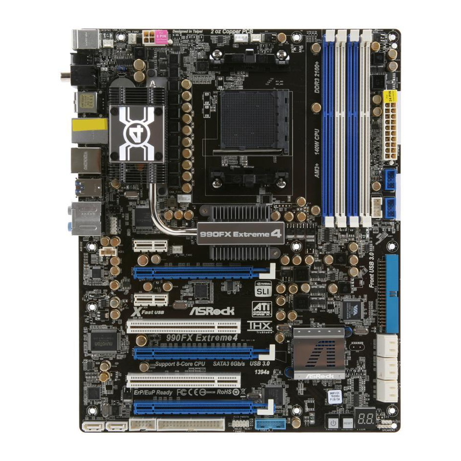
Page 2: Motherboard Layout
Primary IDE Connector (IDE1, Blue) Internal Audio Connector: CD1 (White) SATA3 Connector (SATA3_5_6, White) Front Panel Audio Header SATA3 Connector (SATA3_3_4, White) (HD_AUDIO1, White) SATA3 Connector (SATA3_1_2, White) Infrared Module Header (IR1) Power LED Header (PLED1) Chassis Fan Connector (CHA_FAN1) ASRock 990FX Extreme4 Motherboard... - Page 3 See the table below for connection details in accordance with the type of speaker you use. TABLE for Audio Output Connection Audio Output Channels Front Speaker Rear Speaker Central / Bass Side Speaker (No. 9) (No. 6) (No. 7) (No. 5) ASRock 990FX Extreme4 Motherboard...
- Page 4 Choose “2CH”, “4CH”, “6CH”, or “8CH” and then you are allowed to select “Realtek HDA Pri- mary output” to use Rear Speaker, Central/Bass, and Front Speaker, or select “Realtek HDA Audio 2nd output” to use front panel audio. *** eSATA3 connector supports SATA Gen3 in cable 1M. ASRock 990FX Extreme4 Motherboard...
-
Page 5: Package Contents
In case any modifi cations of this manual occur, the updated ver- sion will be available on ASRock website without further notice. You may fi nd the latest VGA cards and CPU support lists on ASRock website as well. ASRock website http://www.asrock.com... -
Page 6: Specifications
(Realtek ALC892 Audio Codec) - Premium Blu-ray audio support - PCIE x1 Gigabit LAN 10/100/1000 Mb/s - Broadcom BCM57781 - Supports Wake-On-LAN - Supports Energy Effi cient Ethernet 802.3az - Supports PXE Rear Panel I/O I/O Panel ASRock 990FX Extreme4 Motherboard... - Page 7 - 1 x USB 3.0 header (supports 2 USB 3.0 ports) - 1 x Dr. Debug (7-Segment Debug LED) Smart Switch - 1 x Clear CMOS Switch with LED - 1 x Power Switch with LED ASRock 990FX Extreme4 Motherboard...
- Page 8 / Vista 64-bit / XP / XP 64-bit compliant Certifi cations - FCC, CE, WHQL - ErP/EuP Ready (ErP/EuP ready power supply is required) (see CAUTION 14) * For detailed product information, please visit our website: http://www.asrock.com ASRock 990FX Extreme4 Motherboard...
- Page 9 CAUTION! ASRock UCC (Unlock CPU Core) feature simplifi es AMD CPU activa- tion. As long as a simple switch of the UEFI option “ASRock UCC”, you can unlock the extra CPU core to enjoy an instant performance boost. When UCC feature is enabled, the dual-core or triple-core CPU will boost...
- Page 10 Please visit our website for the operation procedures of ASRock Extreme Tuning Utility (AXTU). ASRock website: http://www.asrock.com ASRock Instant Flash is a BIOS fl ash utility embedded in Flash ROM. This convenient BIOS update tool allows you to update system BIOS ®...
- Page 11 Intel’s suggestion, the EuP ready power supply must meet the standard of 5v standby power effi ciency is higher than 50% under 100 mA current consumption. For EuP ready power supply selection, we recommend you checking with the power supply manufacturer for more details. ASRock 990FX Extreme4 Motherboard...
- Page 12 When placing screws into the screw holes to secure the mother- board to the chassis, please do not over-tighten the screws! Doing so may damage the motherboard. ASRock 990FX Extreme4 Motherboard...
- Page 13 Then connect the CPU fan to the CPU FAN connector (CPU_FAN1, see Page 2, No. 6 or CPU_FAN2, see Page 2, No. 7). For proper installation, please kindly refer to the instruc- tion manuals of the CPU fan and the heatsink. ASRock 990FX Extreme4 Motherboard...
- Page 14 It is not allowed to install a DDR or DDR2 memory module into DDR3 slot; otherwise, this motherboard and DIMM may be dam- aged. If you adopt DDR3 2100 memory modules on this motherboard, it is recommended to install them on DDR3_A2 and DDR3_B2 slots. ASRock 990FX Extreme4 Motherboard...
-
Page 15: Installing A Dimm
DIMM if you force the DIMM into the slot at incorrect orientation. Step 3. Firmly insert the DIMM into the slot until the retaining clips at both ends fully snap back in place and the DIMM is properly seated. ASRock 990FX Extreme4 Motherboard... -
Page 16: Installing An Expansion Card
Align the card connector with the slot and press fi rmly until the card is completely seated on the slot. Step 5. Fasten the card to the chassis with screws. Step 6. Replace the system cover. ASRock 990FX Extreme4 Motherboard... - Page 17 PCIE2 slot and the other graphics card to PCIE4 slot. Make sure that the cards are properly seated on the slots. Step2. If required, connect the auxiliary power source to the PCI Express graphics cards. ASRock 990FX Extreme4 Motherboard...
- Page 18 Step3. Align and insert ASRock SLI_Bridge_2S Card to the goldfi ngers on each graphics card. Make sure ASRock SLI_Bridge_2S Card is fi rmly in place. ASRock SLI_Bridge_2S Card Step4. Connect a VGA cable or a DVI cable to the monitor connector or the DVI connector of the graphics card that is inserted to PCIE2 slot.
- Page 19 Quad SLI feature. ® * SLI appearing here is a registered trademark of NVIDIA Technologies Inc., and is used only for identifi cation or explanation and to the owners’ benefi t, without intent to infringe. ASRock 990FX Extreme4 Motherboard...
-
Page 20: Operation Guide
Step 1. Insert one Radeon graphics card into PCIE2 slot and the other Radeon graphics card to PCIE4 slot. Make sure that the cards are properly seated on the slots. ASRock 990FX Extreme4 Motherboard... - Page 21 Connect the DVI monitor cable to the DVI connector on the Radeon graph- ics card on PCIE2 slot. (You may use the DVI to D-Sub adapter to convert the DVI connector to D-Sub interface, and then connect the D-Sub monitor cable to the DVI to D-Sub adapter.) ASRock 990FX Extreme4 Motherboard...
- Page 22 PCIE4 slots, and use the other CrossFire Bridge to connect Radeon graphics cards on PCIE4 and PCIE5 slots. (CrossFire Bridge is provided with the graphics card you purchase, not bundled with this motherboard. Please refer to your graphics card vendor for details.) ASRock 990FX Extreme4 Motherboard...
- Page 23 Connect the DVI monitor cable to the DVI connector on the Radeon graph- ics card on PCIE2 slot. (You may use the DVI to D-Sub adapter to convert the DVI connector to D-Sub interface, and then connect the D-Sub monitor cable to the DVI to D-Sub adapter.) ASRock 990FX Extreme4 Motherboard...
- Page 24 Double-click “ATI Catalyst Control Center”. Click “View”, select “CrossFi- ”, and then check the item “Enable CrossFireX ”. Select “2 GPUs” and click “Apply” (if you install two Radeon graphics cards). Select “3 GPUs” and click “OK” (if you install three Radeon graphics cards). ASRock 990FX Extreme4 Motherboard...
-
Page 25: Surround Display Feature
This motherboard supports Surround Display upgrade. With the external add-on PCI Express VGA cards, you can easily enjoy the benefi ts of Surround Display feature. For the detailed instruction, please refer to the document at the following path in the Support CD: ..\ Surround Display Information ASRock 990FX Extreme4 Motherboard... -
Page 26: Jumpers Setup
Please be noted that the password, date, time, user default profi le, 1394 GUID and MAC address will be cleared only if the CMOS battery is removed. The Clear CMOS Switch has the same function as the Clear CMOS jumper. ASRock 990FX Extreme4 Motherboard... -
Page 27: Onboard Headers And Connectors
SATA power cable to the (Optional) power connector on each drive. connect to the SATA Then connect the white end of HDD power connector SATA power cable to the power connect to the power supply connector of the power supply. ASRock 990FX Extreme4 Motherboard... - Page 28 USB 3.0 header on this (see p.2 No. 28) motherboard. This USB 3.0 header can support two USB 3.0 ports. Infrared Module Header This header supports an optional wireless transmitting (5-pin IR1) and receiving infrared module. (see p.2 No. 44) ASRock 990FX Extreme4 Motherboard...
- Page 29 Note the positive and negative pins before connecting the cables. PWRBTN (Power Switch): Connect to the power switch on the chassis front panel. You may con- fi gure the way to turn off your system using the power switch. ASRock 990FX Extreme4 Motherboard...
- Page 30 (see p.2 No. 45) +12V CHA_FAN_SPEED ground pin. CHA_FAN1/2/3 fan FAN_SPEED_CONTROL speed can be controlled through CHA_FAN_SPEED UEFI or AXTU. (3-pin CHA_FAN2) +12V (see p.2 No. 4) +12V (3-pin CHA_FAN3) CHA_FAN_SPEED (see p.2 No. 2) ASRock 990FX Extreme4 Motherboard...
- Page 31 Though this motherboard provides 8-pin ATX 12V power connector, it can still work if you adopt a traditional 4-pin ATX 12V power supply. To use the 4-pin ATX power supply, please plug your power supply along with Pin 1 and Pin 5. 4-Pin ATX 12V Power Supply Installation ASRock 990FX Extreme4 Motherboard...
- Page 32 Panel, four HDD screws, and six chassis screws. Intall the Front USB 3.0 Panel into Step 3 Screw the Front USB 3.0 Panel to Step 4 the 2.5” drive bay of the chassis. the drive bay with six chassis screws. ASRock 990FX Extreme4 Motherboard...
-
Page 33: Smart Switches
Reset Switch is a smart switch, allowing users to quickly reset (RSTBTN) the system. (see p.2 No. 25) Clear CMOS Switch Clear CMOS Switch is a smart switch, allowing users to quickly (CLRCBTN) clear the CMOS values (see p.3 No. 17) ASRock 990FX Extreme4 Motherboard... - Page 34 CPU post-memory initialization is started 0x33 CPU post-memory initialization. Cache initialization 0x34 CPU post-memory initialization. Application Processor(s) (AP) initialization 0x35 CPU post-memory initialization. Boot Strap Processor (BSP) selection 0x36 CPU post-memory initialization. System Management Mode (SMM) initialization ASRock 990FX Extreme4 Motherboard...
- Page 35 Reserved for future AMI progress codes 0xF8 Recovery PPI is not available 0xF9 Recovery capsule is not found 0xFA Invalid recovery capsule 0xFB – 0xFF Reserved for future AMI error codes 0x60 DXE Core is started 0x61 NVRAM initialization ASRock 990FX Extreme4 Motherboard...
- Page 36 0x9C USB Detect 0x9D USB Enable 0x9E – 0x9F Reserved for future AMI codes 0xA0 IDE initialization is started 0xA1 IDE Reset 0xA2 IDE Detect 0xA3 IDE Enable 0xA4 SCSI initialization is started 0xA5 SCSI Reset ASRock 990FX Extreme4 Motherboard...
- Page 37 No Console Input Devices are found 0xD8 Invalid password 0xD9 Error loading Boot Option (LoadImage returned error) 0xDA Boot Option is failed (StartImage returned error) 0xDB Flash update is failed 0xDC Reset protocol is not available ASRock 990FX Extreme4 Motherboard...
-
Page 38: Driver Installation Guide
B.Set the option “SATA Mode” to [IDE]. (For SATA3_1 to SATA3_6 ports.) Set the option “Marvell SATA3 Operation Mode” to [IDE]. (For SATA3_7 and SATA3_8 ports.) ® STEP 2: Install Windows XP / XP 64-bit OS on your system. ASRock 990FX Extreme4 Motherboard... -
Page 39: Untied Overclocking Technology
PCI / PCIE buses are in the fi xed mode so that FSB can operate under a more stable overclocking environment. Please refer to the warning on page 9 for the possible overclocking risk before you apply Untied Overclocking Technology. ASRock 990FX Extreme4 Motherboard... -
Page 40: Bios Information
It will display the Main Menu automatically if “AUTORUN” is enabled in your computer. If the Main Menu does not appear automatically, locate and double-click on the fi le “ASSETUP.EXE” from the BIN folder in the Support CD to display the menus. ASRock 990FX Extreme4 Motherboard... - Page 41 1. Einführung Wir danken Ihnen für den Kauf des ASRock 990FX Extreme4 Motherboard, ein zu- verlässiges Produkt, welches unter den ständigen, strengen Qualitätskontrollen von ASRock gefertigt wurde. Es bietet Ihnen exzellente Leistung und robustes Design, gemäß der Verpflichtung von ASRock zu Qualität und Halbarkeit. Diese Schnel- linstallationsanleitung führt in das Motherboard und die schrittweise Installation...
- Page 42 CrossFireX ® - NVIDIA Quad SLI und SLI Audio - 7.1 CH HD Audio mit dem Inhalt Schutz (Realtek ALC892 Audio Codec) - Premium Blu-ray-Audio-Unterstützung - PCIE x1 Gigabit LAN 10/100/1000 Mb/s - Broadcom BCM57781 ASRock 990FX Extreme4 Motherboard...
- Page 43 - 1 x ATA133 IDE-Anschlüsse (Unterstützt bis 2 IDE-Geräte) - 1 x FDD-Anschlüsse - 1 x Infrarot-Modul-Header - 1 x COM-Anschluss-Header - 1 x IEEE 1394-Anschluss - 1 x HDMI_SPDIF-Anschluss - 1 x Betriebs-LED-Header - CPU/Gehäuse/Stromlüfter-Anschluss - 24-pin ATX-Netz-Header - 8-pin anschluss für 12V-ATX-Netzteil ASRock 990FX Extreme4 Motherboard...
- Page 44 - ASRock Extreme Tuning Utility (AXTU) Eigenschaft (siehe VORSICHT 7) - ASRock Sofortstart - ASRock Instant Flash (siehe VORSICHT 8) - ASRock APP Charger (siehe VORSICHT 9) - ASRock XFast USB (siehe VORSICHT 10) - ASRock ein/aus-Wiedergabetechnologie (siehe VORSICHT 11)
- Page 45 Verantwortung für mögliche Schäden, die aufgrund von Overclocking verursacht wur- den. VORSICHT! Die ASRock UCC-Funktion (Unlock CPU Core; zu Deutsch: CPU-Kern freigeben) vereinfacht die AMD-CPU-Aktivierung. Zur Freigabe des zusätzli- chen CPU-Kerns müssen Sie lediglich die UEFI-Option „Unlock CPU Core“...
- Page 46 APP Charger. Installieren Sie einfach den ASRock APP Charger-Treiber; dadurch lädt sich Ihr iPhone wesentlich schneller über einen Computer auf – genaugenommen bis zu 40 % schneller als zuvor. Der ASRock APP Charger ermöglicht Ihnen die schnelle Aufl adung mehrerer Apple-Geräte gleichzeitig;...
- Page 47 10. ASRocks XFast USB dient der Steigerung der Leistungsfähigkeit Ihrer USB-Speichergeräte. Die Leistung kann je nach Eigenschaften des Gerä- tes variieren. 11. Durch die ASRock ein/aus-Wiedergabetechnologie können Sie großartige Klangerlebnisse von portablen Audiogeräten, wie z. B. MP3-Playern oder Mobiltelefonen, an Ihrem PC genießen – selbst wenn der PC ausge- schaltet ist (oder sich im ACPI S5-Modus befi...
- Page 48 Unterlage, oder zurück in die Tüte, mit der die Komponente geliefert wurde. Wenn Sie das Motherboard mit den Schrauben an dem Computergehäuse befestigen, überziehen Sie bitte die Schrauben nicht! Das Motherboard kann sonst beschädigt werden. ASRock 990FX Extreme4 Motherboard...
- Page 49 Kontakt zueinander haben. Verbinden Sie dann den CPU-Lüfter mit dem CPU-LÜFTER-Anschluss (CPU_FAN1, siehe Seite 2, Nr. 6 oder CPU_FAN2, siehe Seite 2, Nr. 7). Beziehen Sie sich für eine richtige Installation auf die Handbücher des CPU-Lüfters und des Kühlkörpers. ASRock 990FX Extreme4 Motherboard...
- Page 50 2.3 Installation der Speichermodule (DIMM) Die Motherboards 990FX Extreme4 bieten vier 240-pol. DDR3 (Double Data Rate 3) DIMM-Steckplätze und unterstützen die Dual-Kanal-Speichertechnologie. Für die Dual-Kanalkonfi guration dürfen Sie nur identische (gleiche Marke, Geschwindigkeit, Größe und gleicher Chiptyp) DDR3 DIMM-Paare in den Steckplätzen gleicher Farbe installieren.
- Page 51 Steckplätze zu zwingen, führt dies zu dauerhaften Schäden am Mainboard und am DIMM-Modul. Schritt 3: Drücken Sie die DIMM-Module fest in die Steckplätze, so dass die Halteklammern an beiden Enden des Moduls einschnappen und das DIMM-Modul fest an Ort und Stelle sitzt. ASRock 990FX Extreme4 Motherboard...
- Page 52 2.4 Erweiterungssteckplätze: (PCI- und PCI Express-Slots): Es stehen 2 PCI- und 5 PCI Express-Slot auf dem 990FX EXtreme4 Motherboard zur Verfügung. PCI-Slots: PCI-Slots werden zur Installation von Erweiterungskarten mit dem 32bit PCI-Interface genutzt. PCI Express-Slots: PCIE1 / PCIE3 (PCIE x1-Steckplatz; weiß) wird für PCI Express x1 Lane-Breite-Karten verwendet, z.B.
- Page 53 / 7 unterstützt. Die 3-Way CrossFireX -und Quad CrossFireX -Funktion wird nur vom Betriebssystem ® Windows Vista / 7 unterstützt. Schauen Sie auf der AMD-Website nach, ob es CrossFireX -Treiber-Updates gibt. Beachten Sie den detailliert erklärten Installationsablauf auf Seite ASRock 990FX Extreme4 Motherboard...
-
Page 54: Einstellung Der Jumper
CMOS gelöscht wurde. Wenn Sie den CMOS- Inhalt gleich nach dem Aktualisieren des BIOS löschen müssen, müssen Sie zuerst das System starten und dann wieder ausschalten, bevor Sie den CMOS-Inhalt löschen. Der CMOS löschen-Schalter hat dieselbe Funktion wie der CMOS löschen-Jumper. ASRock 990FX Extreme4 Motherboard... - Page 55 SATA3 Festplatte oder das (Option) SATA3 Verbindungsstück auf dieser Hauptplatine angeschlossen werden. Audiokabel (3,5 mm, Klinke) Beide Enden des 3,5-mm-Klin kenaudiokabels können an (Option) portable Audiogeräte, wie z. B. MP3-Player und Mobiltelefone, oder den Line-in-Port Ihres PCs angeschlossen werden. ASRock 990FX Extreme4 Motherboard...
- Page 56 (siehe S.2 - No. 28) Header an diesem Motherboard. Dieser USB 3.0- Header kann zwei USB 3.0- Ports unterstützen. Infrarot-Modul-Header Dieser Header unterstützt ein optionales, drahtloses Sende- (5-pin IR1) und Empfangs-Infrarotmodul. (siehe S.2 - No. 44) ASRock 990FX Extreme4 Motherboard...
- Page 57 (siehe S.2 - No. 29) Schließen Sie die Ein-/Austaste, die Reset-Taste und die Systemstatusanzeige am Gehäuse an diesen Header an; befolgen Sie dabei die nachstehenden Hinweise zur Pinbelegung. Beachten Sie die positiven und negativen Pins, bevor Sie die Kabel anschließen. ASRock 990FX Extreme4 Motherboard...
- Page 58 S1-Zustand. Im S3-/S4- oder S5-Zustand (ausgeschaltet) leuchtet die LED nicht. Gehäuse- und Stromlüfteranschlüsse Verbinden Sie die Lüfterkabel mit den Lüfteranschlüssen, (4-pin CHA_FAN1) wobei der schwarze Draht an (siehe S.2, No. 45) +12V CHA_FAN_SPEED den Schutzleiterstift FAN_SPEED_CONTROL ASRock 990FX Extreme4 Motherboard...
- Page 59 Obwohl dieses Motherboard einen 24-pol. ATX- Stromanschluss bietet, kann es auch mit einem modifi zierten traditionellen 20-pol. ATX-Netzteil verwendet werden. Um ein 20-pol. ATX-Netzteil zu verwenden, stecken Sie den Stecker mit Pin 1 und Pin 13 ein. Installation eines 20-pol. ATX-Netzteils ASRock 990FX Extreme4 Motherboard...
- Page 60 (2-pin HDMI_SPDIF1) Audioausgang für eine HDMI- (siehe S.2 - No. 1) VGA-Karte zur Verfügung und ermöglicht den Anschluss von HDMI-Digitalgeräten wie Fernsehgeräten, Projektoren, LCD-Geräten an das System. Bitte verbinden Sie den HDMI_SPDIF-Anschluss der HDMI-VGA-Karte mit diesem Anschluss. ASRock 990FX Extreme4 Motherboard...
- Page 61 Schließen Sie das USB 3.0-Kabel an USB 3.0-Panel. das USB 3.0-Blech an. Schritt 3 Schritt 4 Fixieren Sie das USB 3.0-Blech mit Setzen Sie das USB 3.0-Blech an Schrauben an der Rückwand. der Rückwand des Gehäuses ein. ASRock 990FX Extreme4 Motherboard...
- Page 62 Schnellschalter, mit dem (RSTBTN) Benutzer das System schnell (siehe S.2 - No. 25) zurücksetzen können. CMOS löschen-Schalter Der CMOS löschen-Schalter ist ein Schnellschalter, mit dem (CLRCBTN) Benutzer die CMOS-Werte (siehe S.3 - No. 17) schnell löschen können. ASRock 990FX Extreme4 Motherboard...
- Page 63 B.Stellen Sie “SATA Mode” (SATA-Modus) auf [IDE]. (Für SATA3_1 zu SATA3_6.) Stellen Sie “Marvell SATA3 Operation Mode” (SATA-Modus) auf [IDE]. (Für SATA3_7 und SATA3_8.) ® SCHRITT 2: Installieren Sie Windows XP / XP 64-Bit in Ihrem System. ASRock 990FX Extreme4 Motherboard...
- Page 64 B.Stellen Sie “SATA Mode” (SATA-Modus) auf [AHCI]. (Für SATA3_1 zu SATA3_6.) Stellen Sie “Marvell SATA3 Operation Mode” (SATA-Modus) auf [AHCI]. (Für SATA3_7 und SATA3_8.) ® SCHRITT 2: Installieren Sie Windows 7 / 7 64-Bit / Vista / Vista 64-Bit in Ihrem System. ASRock 990FX Extreme4 Motherboard...
- Page 65 ASSETUP.EXE im BIN-Verzeichnis der Support-CD, um die Menüs aufzurufen. Das Setup-Programm soll es Ihnen so leicht wie möglich machen. Es ist menüges- teuert, d.h. Sie können in den verschiedenen Untermenüs Ihre Auswahl treffen und die Programme werden dann automatisch installiert. ASRock 990FX Extreme4 Motherboard...
- Page 66 1. Introduction Merci pour votre achat d’une carte mère ASRock 990FX Extreme4, une carte mère très fi able produite selon les critères de qualité rigoureux de ASRock. Elle offre des performances excellentes et une conception robuste conformément à l’engagement d’ASRock sur la qualité et la fi abilité au long terme.
- Page 67 - Prend en charge NVIDIA Quad SLI et SLI Audio - 7,1 CH HD Audio avec protection de contenu (Realtek ALC892 Audio Codec) - Prise en charge de l’audio Premium Blu-ray - PCIE x1 Gigabit LAN 10/100/1000 Mb/s ASRock 990FX Extreme4 Motherboard...
- Page 68 - 1 x Port Disquette - 1 x En-tête du module infrarouge - 1 x En-tête de port COM - 1 x Connecteur IEEE 1394 - 1 x Connecteur HDMI_SPDIF - 1 x LED di accensione ASRock 990FX Extreme4 Motherboard...
- Page 69 - Utilitaire ASRock Extreme Tuning (AXTU) unique (voir ATTENTION 7) - ASRock l'Instant Boot - ASRock Instant Flash (voir ATTENTION 8) - Chargeur ASRock APP (voir ATTENTION 9) - ASRock XFast USB (voir ATTENTION 10) - Technologie Lecture Marche/Arrêt ASRock (voir ATTENTION 11) - L’accélérateur hybride:...
- Page 70 ATTENTION! La fonction ASRock UCC (Unlock CPU Core : Déverrouillage du coeur du processeur) permet de simplifi er l’activation des processeurs AMD. Il vous suffi t de sélectionner dans le UEFI l’option « Unlock CPU Core »...
- Page 71 ASRock Extreme Tuning Utility (AXTU). Site Web de ASRock : http://www.asrock.com O ASRock Instant Flash é um utilitário de fl ash do BIOS incorporado na memória Flash ROM. Esta prática ferramenta de actualização do BIOS permite-lhe actualizar o BIOS do sistema sem necessitar de entrar nos ®...
- Page 72 APP est installé, vous découvrez un mode de mise en charge tout à fait inédit. Site web ASRock : http://www.asrock.com/Feature/AppCharger/index.asp 10. ASRock XFast USB permet d’améliorer les performances de votre péri- phérique de stockage USB. Les performances réelles dépendent des propriétés du périphérique.
- Page 73 5. Lorsque vous placez les vis dans les orifi ces pour vis pour fi xer la carte mère sur le châssis, ne serrez pas trop les vis ! Vous risquez sinon d’endommager la carte mère. ASRock 990FX Extreme4 Motherboard...
- Page 74 CPU à la prise du VENTILATEUR DU CPU (CPU_FAN1, reportez- vous en page 2, No. 6 ou CPU_FAN2, reportez-vous en page 2, No. 7). Pour une bonne installation, veuillez vous référer aux manuels d’instruction sur le ventilateur du CPU et le dissipateur. ASRock 990FX Extreme4 Motherboard...
- Page 75 2.3 Installation des modules m émoire [DIMM] La carte mère 990FX Extreme4 dispose de quatre emplacements DIMM DDR3 (Double Data Rate 3) de 240-broches, et supporte la Technologie de Mémoire à Canal Double. Pour effectuer une confi guration à canal double, vous devez toujours installer des paires de DIMM DDR3 identiques (de la même marque, de la même...
- Page 76 DIMM. Etape 3. Insérez fermement le module DIMM dans son emplacement jusqu’à ce que les clips de maintien situés aux deux extrémités se ferment complètement et que le module DIMM soit inséré correctement. ASRock 990FX Extreme4 Motherboard...
- Page 77 2.4 Slot d’extension (Slots PCI et Slots PCI Express) Il y a 2 ports PCI et 5 ports PCI Express sur la carte mère 990FX Extreme4. Slots PCI: Les slots PCI sont utilisés pour installer des cartes d’extension dotées d’une interface PCI 32 bits.
- Page 78 Windows Vista / 7 uniquement. Veuillez consulter le site d’AMD pour les mises à jour de driver AMD CrossFireX . Veuillez suivre les instructions d’installation de la page pour plus de détails. ASRock 990FX Extreme4 Motherboard...
- Page 79 CMOS. Veuillez noter que le mot de passe, la date, l’heure, le profi l par défaut de l’utilisateur, 1394 GUID et l’adresse MAC seront effacés seulement si la batterie du CMOS est enlevée. Le commutateur Effacer CMOS présente la même fonction que le cavalier Effacer CMOS. ASRock 990FX Extreme4 Motherboard...
- Page 80 Câble audio 3,5mm L’une des extrémités du câble audio 3,5mm peut être (en option) branchée sur des appareils audio portatifs comme un lecteur MP3 ou un téléphone portable, ou le port Entrée Ligne de votre PC. ASRock 990FX Extreme4 Motherboard...
- Page 81 USB 3.0 par défaut sur le (USB3_0_1 br.19) panneau E/S, il y a une barrette (voir p.2 No. 28) USB 3.0 sur la carte mère. Cette barrette USB 3.0 peut prendre en charge deux ports USB 3.0. ASRock 990FX Extreme4 Motherboard...
- Page 82 Allez sur l’onglet “FrontMic” (Micro avant) sur le Panneau de contrôle Realtek. Ajustez “Recording Volume” (Volume d’enregistrement). En-tête du panneau système Cet en-tête permet d’utiliser plusieurs fonctions du (PANEL1 br.9) panneau système frontal. (voir p.2 No. 29) ASRock 990FX Extreme4 Motherboard...
- Page 83 (3-pin PLED1) alimentazione del sistema. Il (vedi p.2 Nr. 22) LED è acceso quando il sistema è in funzione. Il LED continua a lampeggiare in stato S1. Il LED è spento in stato S3/S4 o S5 (spegnimento). ASRock 990FX Extreme4 Motherboard...
- Page 84 ATX 24 broches, elle peut encore fonctionner si vous adopter une alimentation traditionnelle ATX 20 broches. Pour utiliser une alimentation ATX 20 broches, branchez à l’alimentation électrique ainsi qu’aux broches 1 et 13. 20-Installation de l’alimentation électrique ATX ASRock 990FX Extreme4 Motherboard...
- Page 85 SPDIF vers la carte VGA HDMI, (voir p.2 No. 1) et permettant au système de se connecter au un téléviseur numérique HDMI /un projecteur / un périphérique LCD. Veuillez brancher le connecteur HDMI_SPDIF de la carte VGA HDMI sur ce connecteur. ASRock 990FX Extreme4 Motherboard...
- Page 86 Assemblez le câble USB 3.0 et le avant USB 3.0. support arrière USB 3.0. Étape 3 Étape 4 Vissez les deux vis dans le support Placez le support arrière USB 3.0 arrière USB 3.0. dans le châssis. ASRock 990FX Extreme4 Motherboard...
- Page 87 64-bit / XP / XP 64-bit avec fonctions RAID ® Si vous souhaitez installer Windows 7 / 7 64-bit / Vista / Vista 64-bit / XP / XP 64-bit OS sur votre lecteur de disque dur SATA3 avec les fonctions RAID, veuillez ASRock 990FX Extreme4 Motherboard...
- Page 88 B.Réglez «SATA Mode « sur [IDE]. (Pour SATA3_1 à SATA3_6.) Réglez «Marvell SATA3 Operation Mode « sur [IDE]. (Pour SATA3_7 à SATA3_8.) ® ETAPE 2: Installer le système d’exploitation Windows 7 / 7 64-bit / Vista / Vista 64-bit sur votre système. ASRock 990FX Extreme4 Motherboard...
- Page 89 B.Réglez «SATA Mode « sur [AHCI]. (Pour SATA3_1 à SATA3_6.) Réglez «Marvell SATA3 Operation Mode « sur [AHCI]. (Pour SATA3_7 à SATA3_8.) ® ETAPE 2: Installer le système d’exploitation Windows 7 / 7 64-bit / Vista / Vista 64-bit sur votre système. ASRock 990FX Extreme4 Motherboard...
-
Page 90: Informations Sur Le Cd De Support
CD-ROM. Le Menu principal s’affi che automatiquement si “AUTORUN” est activé dans votre ordinateur. Si le Menu principal n’apparaît pas automatiquement, locali- sez dans le CD technique le fi chier “ASSETUP.EXE” dans le dossier BIN et double- cliquez dessus pour affi cher les menus. ASRock 990FX Extreme4 Motherboard... - Page 91 1. Introduzione Grazie per aver scelto una scheda madre ASRock 990FX Extreme4, una scheda madre affi dabile prodotta secondo i severi criteri di qualità ASRock. Le prestazioni eccellenti e il design robusto si conformano all’impegno di ASRock nella ricerca della qualità e della resistenza.
- Page 92 - 7.1 CH HD Audio con protezioni contenuti (Realtek ALC892 Audio Codec) - Supporto audio Blu-ray Premium - PCIE x1 Gigabit LAN 10/100/1000 Mb/s - Broadcom BCM7781 - Supporta Wake-On-LAN - Supporto di Energy Effi cient Ethernet 802.3az ASRock 990FX Extreme4 Motherboard...
- Page 93 - Connettore audio sul pannello frontale - 2 x Collettore USB 2.0 (supporta 4 porte USB 2.0) - 1 x Collettore USB 3.0 (supporta 2 porte USB 3.0) - 1 x Dr. Debug (LED debug con 7 segmenti) ASRock 990FX Extreme4 Motherboard...
- Page 94 / XP / XP 64 bit Certifi cazioni - FCC, CE, WHQL - Predisposto ErP/EuP (è necessaria l’alimentazione predis posta per il sistema ErP/EuP) (vedi ATTENZIONE 14) * Per ulteriori informazioni, prego visitare il nostro sito internet: http://www.asrock.com ASRock 990FX Extreme4 Motherboard...
- Page 95 ATTENZIONE! La funzione ASRock UCC (Unlock CPU Core, Sblocca CPU Core) sem- plifi ca l’attivazione della CPU AMD. È una semplice voce d’attivazione delle opzioni UEFI chiamata “Unlock CPU Core” (Sblocca CPU Core) che permette di sbloccare il core CPU extra per sfruttare un’immediata acce-...
- Page 96 Windows . Con questa utilità, si può premere il tasto <F6> durante il POST, oppure il tasto <F2> nel menu BIOS per accedere ad ASRock In- stant Flash. Avviare questo strumento e salvare il nuovo fi le BIOS nell’unità...
- Page 97 10. ASRock XFast USB può accelerare le prestazioni del dispositivo d’archi- viazione USB. Le prestazioni dipendono dalle proprietà del dispositivo. 11. La tecnologia ASRock On/Off Play consente agli utenti di godere di una esperienza audio eccezionale tramite i dispositivi audio portatili come i lettori MP3 o il cellulare sul proprio PC, anche quando il PC è...
- Page 98 5. Nell’usare i giraviti per fi ssare la scheda madre al telaio non serrare eccessivamente le viti! Altrimenti si rischia di danneg- giare la scheda madre. ASRock 990FX Extreme4 Motherboard...
- Page 99 PU FAN (CPU_FAN1, fare riferimento a pagina 2, Numero 6 o CPU_FAN2, fare riferimento a pagina 2, Numero 7). Per eseguire un’installazione appropriata, fare riferimento al manuale d’istruzioni della ventolina CPU e del dispersore di calore. ASRock 990FX Extreme4 Motherboard...
- Page 100 2.3 Installazione dei moduli di memoria (DIMM) La scheda madre 990FX Extreme4 fornisce quattro alloggiamenti DIMM DDR3 (Double Data Rate 3) a 240 pin, e supporta la tecnologia Dual Channel Memory. Per la confi gurazione a due canali, è necessario installare sempre coppie identiche (stessa marca, velocità, dimensioni e tipo di chip) di DIMM DDR3 negli alloggiamenti...
- Page 101 DIMM stessa. Fase 3. Inserire saldamente la DIMM nello slot fi no a far scattare completamente in posizione i fermagli di ritegno alle due estremità e fi no ad installare correttamente la DIMM nella sua sede. ASRock 990FX Extreme4 Motherboard...
- Page 102 2.4 Slot di espansione (Slot PCI ed Slot PCI Express) Sulla scheda madre 990FX Extreme4 c’è 2 slot PCI ed 5 slot PCI Express. Slot PCI: Sono utilizzati per installare schede di espansione con Interfaccia PCI a 32-bit. Slot PCI Express: L’alloggio PCIE1 / PCIE3 (PCIE x1; bianco) è usato per le schede PCI Express x1 lane, come schede Gigabit LAN, SATA2.
- Page 103 Quad CrossFireX è supportata solo dal sistema operativo ® Windows Vista / 7. Visitare il sito AMD per gli aggiornamenti dei driver AMD CrossFireX . Attenersi alle procedure d’installazione, a pagina 20, per i dettagli. ASRock 990FX Extreme4 Motherboard...
- Page 104 1394 GUID e indirizzo MAC saranno cancellati solo se è rimossa la batteria della CMOS. L’interruttore Clear CMOS (Cancella CMOS) ha la stessa funzione del jumper Clear CMOS. ASRock 990FX Extreme4 Motherboard...
- Page 105 Serial ATA (SATA) cavo di alimentazione SATA al connettore di alimentazione del (Opzionale) Connettere all’ailmentazio- drive. Poi connettete l’estremità Connettere al gruppo dei dischi SATA bianca del cavo di alimentazio di alimentazione ne SATA al connettore power dell’alimentatore. ASRock 990FX Extreme4 Motherboard...
- Page 106 (vedi p.2 Nr. 44) ricezione senza fi li. Connettori audio interni Permettono di ricevere input stereo audio da fonti di (4-pin CD1) suono come CD-ROM, DVD - (vedi p.2 Nr. 42) ROM,TV tuner, o schede MPEG. ASRock 990FX Extreme4 Motherboard...
- Page 107 Usando l’interruttore d’alimentazione si può confi gurare il modo in cui si spegne il sistema. RESET (interruttore di ripristino): Va collegato all’interruttore di ripristino del pannello frontale del telaio. Premere l’interruttore di ripristino per riavviare il sistema se il computer si ASRock 990FX Extreme4 Motherboard...
- Page 108 La velocità FAN_SPEED_CONTROL della ventola CHA_FAN1/2/3 (3-pin CHA_FAN2) CHA_FAN_SPEED può essere controllata tramite (vedi p.2 Nr. 4) +12V UEFI o AXTU. (3-pin CHA_FAN3) +12V CHA_FAN_SPEED (vedi p.2 Nr. 2) (3-pin PWR_FAN1) PWR_FAN_SPEED (vedi p.2 Nr. 40) +12V ASRock 990FX Extreme4 Motherboard...
- Page 109 12V, l‘unita‘ puo‘ ancora essere funzionante se viene utilizzata una fornitura elettrica tradizionale a 4-pin ATX 12V. Per usare tale fornitura elettrica 4-pin ATX 12V, prego collegare la presa elettrica al Pin 1 e Pin 5. Installazione elettrica 4-Pin ATX 12V ASRock 990FX Extreme4 Motherboard...
- Page 110 SPDIF su scheda (2-pin HDMI_SPDIF1) HDMI VGA, consente al (vedi p.2 Nr. 1) sistema di collegare dispositivi per TV digitale HDMI/proiettori/ LCD . Collegare il connettore HDMI_SPDIF della scheda VGA HDMI a questo header. ASRock 990FX Extreme4 Motherboard...
- Page 111 Svitare le due viti dal pannello USB 3.0 Punto 2 Collegare il cavo USB 3.0 e il anteriore. supporto USB 3.0 posteriore. Punto 3 Punto 4 Avvitare le due viti nel supporto USB 3.0 Inserire il supporto USB 3.0 posteriore. posteriore nel telaio. ASRock 990FX Extreme4 Motherboard...
- Page 112 (vedi p.2 Nr. 25) agli utenti di resettare rapidamente il sistema. Interruttore pulizia CMOS L’interruttore di pulizia CMOS è (CLRCBTN) un interruttore rapido che (vedi p.3 Nr. 17) consente agli utenti di cancellare velocemente i valori CMOS. ASRock 990FX Extreme4 Motherboard...
- Page 113 A.Entrare in UTILIT → UEFI SETUP → Avanzate → Confi gurazione Storage. B.Impostare “SATA Mode” su [IDE]. (Per SATA3_1 a SATA3_6.) Impostare “Marvell SATA3 Operation Mode” su [IDE]. (Per SATA3_7 e SATA3_8.) ® 2° PASSO: Installazione di Windows XP / XP 64-bit sul sistema. ASRock 990FX Extreme4 Motherboard...
- Page 114 B.Impostare “SATA Mode” su [AHCI]. (Per SATA3_1 a SATA3_6.) Impostare “Marvell SATA3 Operation Mode” su [AHCI]. (Per SATA3_7 e SATA3_8.) ® Passo 2: Installazione di Windows 7 / 7 64-bit / Vista / Vista 64-bit sul sistema. ASRock 990FX Extreme4 Motherboard...
- Page 115 Inserire il CD di supporto nel lettore CD-ROM. Se la funzione “AUTORUN” è attivata nel computer, apparirà automaticamente il Menù principale. Se il Menù principale non appare automaticamente, posizionarsi sul fi le “ASSETUP.EXE” nel CESTINO del CD di supporto e cliccare due volte per visualizzare i menù. ASRock 990FX Extreme4 Motherboard...
- Page 116 1. Introducción Gracias por su compra de ASRock 990FX Extreme4 placa madre, una placa de confi anza producida bajo el control de calidad estricto y persistente. La placa madre provee realización excelente con un diseño robusto conforme al compromiso de calidad y resistencia de ASRock.
- Page 117 SLI Audio - 7.1 CH HD Audio con Protección de Contenido (Realtek ALC892 Audio Codec) - Compatible con audio Blu-ray de alta calidad - PCIE x1 Gigabit LAN 10/100/1000 Mb/s - Broadcom BCM57781 - Soporta Wake-On-LAN ASRock 990FX Extreme4 Motherboard...
- Page 118 - 1 x puerto Floppy - 1 x Cabezal de Módulo Infrarrojos - 1 x En-tête de port COM - 1 x cabecera IEEE 1394 - 1 x cabecera HDMI_SPDIF - 1 x cabecera de indicador LED de encendido ASRock 990FX Extreme4 Motherboard...
- Page 119 CD de soport - Controladores, Utilerías, Software de Anti Virus (Versión de prueba), Prueba de CyberLink MediaEspresso 6.5 Característica - ASRock Extreme Tuning Utility (AXTU) (vea ATENCIÓN 7) Única - ASRock Instant Boot - ASRock Instant Flash (vea ATENCIÓN 8) - ASRock APP Charger (vea ATENCIÓN 9)
- Page 120 ATENCIÓN! La función ASRock UCC (Unlock CPU Core, desbloquear núcleo la CPU) simplifica la activación de una CPU AMD. Con sólo activar la opción “Unlock CPU Core” (desbloquear núcleo la CPU) en el UEFI, es posible desbloquear el núcleo de CPU adicional y disfrutar de un aumento de...
- Page 121 . Gracias a esta utilidad, sólo necesitará pulsar <F6> durante la fase POST o pulsar <F2> para acceder al menú de confi guración del BIOS y a la utilidad ASRock Instant Flash. Ejecute esta herramienta y guarde el archivo correspondiente al sistema BIOS nuevo en su unidad fl...
- Page 122 Si desea una forma más rápida y menos limitada de cargar sus disposi- tivos de Apple; como por ejemplo iPhone, iPod o iPad Touch, ASRock ha creado una fantástica solución para usted: ASRock APP Charger. Simplemente mediante la instalación del controlador de APP Charger, podrá...
- Page 123 4. Ponga cualquier componente deslocalizado sobre la bolsa anti-estástica que viene con la placa madre. 5. Al colocar los tornillos en sus agujeros para fi jar la placa madre en el chasis, no los apriete demasiado. Eso podría dañar la placa madre. ASRock 990FX Extreme4 Motherboard...
- Page 124 Conecte entonces el ventilador de la CPU al conector CPU FAN (CPU_FAN1, consulte Página 2, N. 6 o CPU_FAN2, consulte Página 2, N. 7). Para realizar la instalación correctamente, consulte el manual de instrucciones del ventilador de la CPU y el radiador. ASRock 990FX Extreme4 Motherboard...
- Page 125 2.3 Instalación de Memoria La placa 990FX Extreme4 ofrece cuatro ranuras DIMM DDR3 de 240 pines, y soporta Tecnología de Memoria de Doble Canal. Para la confi guración de doble canal, necesitará instalar siempre pares DIMM DDR3 idénticos (de la misma marca, velocidad, tamaño y tipo) en las ranuras del mismo color.
- Page 126 DIMM. Paso 3. Inserte la DIMM con fi rmeza dentro de la ranura hasta que los clips de sujeción de ambos lados queden completamente introducidos en su sitio y la DIMM se haya asentado apropiadamente. ASRock 990FX Extreme4 Motherboard...
- Page 127 2.4 Ranuras de Expansión (ranuras PCI y ranuras PCI Express) La placa madre 990FX Extreme4 cuenta con 2 ranuras PCI y 5 ranuras PCI Ex- press. Ranura PCI: Para instalar tarjetas de expansión que tienen 32-bit Interface PCI. Ranura PCI Express:...
- Page 128 / 7. Consulte el sitio web de AMD si desea obtener más información acerca de las actualizaciones de los controladores de AMD CrossFireX . Por favor, siga los procedimientos de instalación de la página 20 para conocer las instrucciones detalladas. ASRock 990FX Extreme4 Motherboard...
- Page 129 Tenga en cuenta que la contraseña, la fecha, la hora, el perfi l predeterminado del usuario, el GUID 1394 y la dirección MAC solamente se borrará si la batería CMOS se quita. El conmutador Borrar CMOS tiene la misma función que el puente Borrar CMOS. ASRock 990FX Extreme4 Motherboard...
- Page 130 Conecte el extremo negro del de serie ATA (SATA) cable de SATA al conector de energía de la unidad. A (Opcional) Connettere all’ailmentazione continuación, conecte el dei dischi SATA Connettere al gruppo extremo blanco del cable de di alimentazione ASRock 990FX Extreme4 Motherboard...
- Page 131 (5-pin IR1) transmisión y recepción (vea p.2, N. 44) wireless opcional. Conector de audio interno Permite recepción de input audio de fuente sónica como (4-pin CD1) CD-ROM, DVD-ROM, TV tuner, (vea p.2, N. 42) o tarjeta MPEG. ASRock 990FX Extreme4 Motherboard...
- Page 132 Conecte el interruptor de encendido situado en el panel frontal del chasis. Puede confi gurar la forma de apagar su sistema mediante el interruptor de alimentación. RESTABLECER (interruptor de restablecimiento): Conecte el interruptor de restablecimiento situado en el panel frontal del ASRock 990FX Extreme4 Motherboard...
- Page 133 (vea p.2, N. 45) FAN_SPEED_CONTROL masa. La velocidad del venti- CHA_FAN_SPEED (3-pin CHA_FAN2) lador CHA_FAN1/2/3 se puede +12V (vea p.2, N. 4) controlar mediante UEFI o AXTU. +12V (3-pin CHA_FAN3) CHA_FAN_SPEED (vea p.2, N. 2) ASRock 990FX Extreme4 Motherboard...
- Page 134 Tenga en cuenta que es necesario conectar este (8-pin ATX12V1) conector a una toma de (vea p.2, N. 5) corriente con el enchufe ATX 12V, de modo que proporcione sufi ciente electricidad. De lo contrario no se podrá encender. ASRock 990FX Extreme4 Motherboard...
- Page 135 (HDMI_SPDIF1 de 2 pin) VGA HDMI, permite al sistema (vea p.2, N. 1) conectarse a dispositivos de TV Digital HDMI / proyectores / Dispositivos LCD. Conecte el conector HDMI_SPDIF de la tarjeta VGA HDMI a esta cabecera. ASRock 990FX Extreme4 Motherboard...
- Page 136 Guía de instalación del soporte USB 3.0 posterior Paso 1 Paso 2 Desatornille los dos tornillos del panel Coloque el cable USB 3.0 el soporte USB 3.0 frontal. USB 3.0 posterior juntos. ASRock 990FX Extreme4 Motherboard...
- Page 137 CMOS. Conmutador de borrado de memoria CMOS El conmutador de encendido es (CLRCBTN) un conmutador rápido que (vea p.3, N. 17) permite al usuario encender / apagar rápidamente el sistema. ASRock 990FX Extreme4 Motherboard...
- Page 138 B.Confi gure la “SATA Mode” a [IDE]. (Para SATA3_1 a SATA3_6.) Confi gure la “Marvell SATA3 Operation Mode” a [IDE]. (Para SATA3_7 y SATA3_8.) ® PASO 2: Instale el sistema operativo Windows XP / XP 64 bits en su sistema. ASRock 990FX Extreme4 Motherboard...
- Page 139 B.Confi gure la “SATA Mode” a [AHCI]. (Para SATA3_1 a SATA3_6.) Confi gure la “Marvell SATA3 Operation Mode” a [AHCI]. (Para SATA3_7 y SATA3_8.) ® PASO 2: Instale el sistema operativo Windows 7 / 7 64 bits / Vista Vista 64 bits en su sistema. ASRock 990FX Extreme4 Motherboard...
- Page 140 Para iniciar la instalación, ponga el CD en el lector de CD y se des- plegará el Menú Principal automáticamente si «AUTORUN» está habilitado en su computadora. Si el Menú Principal no aparece automáticamente, localice y doble-pulse en el ar- chivo “ASSETUP.EXE” para iniciar la instalación. ASRock 990FX Extreme4 Motherboard...
- Page 141 1 x I/O 1 x П USB 3.0 1 x К USB 3.0 ASRock SLI_Bridge_2S ASRock а и а ® Windows 7 / 7 64-bit / Vista / Vista 64-bit BIOS Storage Configuration (К AHCI. П BIOS ASRock 990FX Extreme4 Motherboard...
- Page 142 - Broadcom BCM57781 Wake-On-LAN - П Ethernet 802.3az - П I/O Panel - 1 x PS/2 - 1 x PS/2 - 1 x Coaxial SPDIF Out - 1 x Optical SPDIF Out - 6 x USB 2.0 ASRock 990FX Extreme4 Motherboard...
- Page 143 - 1 x Dr. Debug (7- - 1 x Clear CMOS - 1 x Power Switch - 1 x Reset Switch BIOS - 32Mb AMI UEFI Legal BIOS ckoro p e ca “Plug and Play” - ACPI 1.1, ASRock 990FX Extreme4 Motherboard...
- Page 144 CPU, VCCM, NB, SB К , А ), П CyberLink MediaEspresso 6.5 я Ж - ASRock Extreme Tuning Utility (AXTU) ( - ASRock Instant Boot Ж - ASRock Instant Flash ( Ж - ASRock APP Charger ( Ж - ASRock XFast USB ( ASRock Ж...
- Page 145 7 / Vista / XP. ® Windows 64-bit П . П 2-, 4-, 6- . 3. ASRock Extreme Tuning Utility (AXTU) – Hardware Monitor ( ), Fan Control ( ), Overclocking (« » ), OC DNA (П « ») and IES (А...
- Page 146 « » IES (А КП П . ASRock Extreme Tuning Utility (AXTU), . А ASRock: http://www.asrock.com ASRock Instant Flash – BIOS, Flash ROM. BIOS ® MS-DOS Windows <F6> (POST) BIOS <F2> ASRock Instant Flash З BIOS USB- . П BIOS, USB- FAT32/16/12.
- Page 147 13. П . П 14. EuP Energy Using Product. . П . К Intel 100 А ( EuP. ASRock 990FX Extreme4 Motherboard...
- Page 148 2. У а вка ATX (12,0 x 9,6 , 30,5 x 24,4 П П П П К А . К ASRock 990FX Extreme4 Motherboard...
- Page 149 П К П 90° З П ША 1. ША 2, ША 3. ША 4. Ц ш я Ц П П П . П . З П П (CPU_FAN1, . 2, 6 / CPU_FAN2, . 2, П ASRock 990FX Extreme4 Motherboard...
- Page 150 DDR3_A2 DDR3_B1 DDR3_B2 З З З З З З З З (3), DDR3 DIMM. (DDR3_A2 DDR3_ (DDR3_A1 DDR3_B1), (DDR3_A2 DDR3_B2). DDR3 DIMM Dual Channel Memory Technology А А DDR3_A1 DDR3_A2), Dual Channel Memory Technology DDR, DDR2 ASRock 990FX Extreme4 Motherboard...
- Page 151 DDR3 ; DIMM DDR3 2100 DDR3_A2 DDR3_B2. я DIMM DIMM DIMM, 2. П DIMM DIMM- П 3. П DIMM- – ASRock 990FX Extreme4 Motherboard...
- Page 152 PCI Express x16 PCIE2. CrossFireX PCI Express x16 PCIE2 PCIE4. x16. 3-Way CrossFireX PCI Express x16 PCIE2, PCIE4 PCIE5. PCIE2 PCIE4 x16, PCIE5 - 4. П (CHA_FAN1, CHA_FAN2 CHA_FAN3) ш я 1. П . П 4. З ASRock 990FX Extreme4 Motherboard...
- Page 153 CrossFireX CrossFireX , 3- CrossFireX Quad CrossFireX CrossFireX ПК. К , CrossFireX CrossFireX Win- ® dows XP Service Pack 2 / Vista / 7. CrossFi- Quad CrossFireX / 7. П ® Windows Vista CrossFireX . 20 ASRock 990FX Extreme4 Motherboard...
- Page 154 . К “ ” (short). “ ” (open). CMOS (CLRCMOS1, . 2, . 3) CMOS П К CLRCMOS1 CMOS. CLRCMOS1. CMOS BIOS. CMOS BIOS, CMOS, . П 1394 GUID MAC- CMOS. П Clear CMOS Clear CMOS. ASRock 990FX Extreme4 Motherboard...
- Page 155 (39- IDE1, . 2, . 18) П П ATA 66/100/133 П . П IDE- Serial ATA (SATA) SATA / SATAII / SATA3 SATAII / SATA3 3,5- 3,5- MP3- К П Serial ATA (SATA) SATA SATA З ASRock 990FX Extreme4 Motherboard...
- Page 156 USB 2.0 DUMMY USB 2.0. USB8_9) . 2, . 13) USB_PWR USB_PWR К ПП USB 3.0 USB 3.0 (19- USB3_0_1) . 2, . 28) USB 3.0. USB 3.0 USB 3.0. К IR1) . 2, . 44) ASRock 990FX Extreme4 Motherboard...
-
Page 157: Table Of Contents
Windows XP / XP 64- «Mixer» ( «Recorder» ( ). З «FrontMic» (П ® Windows 7 / 7 64- , Vista / Vista П «FrontMic» (П Realtek. «Recording Volume» ( К PANEL1) . 2, . 29) ASRock 990FX Extreme4 Motherboard... - Page 158 К П SPEAKER SPEAKER1) DUMMY +5V DUMMY . 2, . 23) П Power LED Power LED PLED1) . 2, . 22) S3/S4 S5 ( П Chassis Power Fan- CHA_FAN1) . 2, . 45) +12V CHA_FAN_SPEED FAN_SPEED_CONTROL ASRock 990FX Extreme4 Motherboard...
- Page 159 . 2, . 40) +12V П CPU_FAN_SPEED +12V FAN_SPEED_CONTROL CPU_FAN1) 1 2 3 4 . 2, . 6) 1-3. К CPU_FAN2) +12V CPU_FAN_SPEED . 2, . 7) К П ATX. (24- ATXPWR1) . 2, . 12) ATX, ATX. ASRock 990FX Extreme4 Motherboard...
- Page 160 +12V +12V RXTPBM_0 RXTPBP_0 . 2, . 15) RXTPAM_0 RXTPAP_0 IEEE 1394 К COM- COM- COM1) . 2, . 31) COM. К К HDMI_SPDIF HDMI_SPDIF HDMI_SPDIF1) VGA- . 2, . 1) HDMI, HDMI. HDMI_SPDIF VGA- HDMI. ASRock 990FX Extreme4 Motherboard...
- Page 161 USB 3.0 З П 2,5”- USB 3.0, USB 3.0 З USB 3.0 USB 3.0 2,5”- П П USB 3.0 USB 3.0 USB 3.0 (USB3_0_1) ш USB 3.0 USB 3.0 USB 3.0. USB 3.0. ASRock 990FX Extreme4 Motherboard...
- Page 162 USB 3.0 CMOS, CMOS, К Power Switch Power Switch (PWRBTN) . 2, . 26) К Reset Switch Reset Switch (RSTBTN) . 2, . 25) К Clear CMOS Switch Clear CMOS Switch (CLRCBTN) . 3, . 17) CMOS. ASRock 990FX Extreme4 Motherboard...
- Page 163 7 / 7 64-bit / Vista / Vista 64-bit / XP / XP 64-bit RAID, ® 2.13.1 Windows XP / XP 64-bit ц я RAID ® Windows XP / XP 64-bit RAID, И ц я SATA3 я ASRock 990FX Extreme4 Motherboard...
- Page 164 SATA3 я ША 1. UEFI. UEFIЎ AdvancedЎ Storage Confi guration. “SATA Mode” [AHCI]. ( SATA3_1 SATA3_6) “Marvell SATA3 Operation Mode” [AHCI]. ( SATA3_7 SATA3_8.) ША 2. ® Windows 7 / 7 64-bit / Vista Vista 64-bit. ASRock 990FX Extreme4 Motherboard...
- Page 165 <Ctrl> + <Alt> + <Delete> . П BIOS Setup PDF) 4. И ц я ® Microsoft ® 64-bit / XP / XP 64-bit. П Windows : 7 / 7 64-bit / Vista / Vista CD-ROM. (AUTORUN), (Main Menu). ASSETUP.EXE ASRock 990FX Extreme4 Motherboard...
- Page 166 önceden haber verilmeksizin değişebilir. Bu belgede değişiklik yapılması durumun -da, güncelleştirilmiş sürüm ayrıca haber verilmeksizin ASRock web sitesinde sunulur. En son VGA kartlarını ve CPU destek listelerini de ASRock web sitesinde bulabilirsiniz. ASRock web sitesi http://www.asrock.com Bu anakartla ilgili teknik desteğe ihtiyacınız olursa, kullandığınız modele özel bilgiler için lütfen web sitemizi ziyaret edin.
- Page 167 - İçerik Korumalı (Realtek ALC892 Ses Kodeki) 7,1 Kanal HD - Premium Blu-ray ses desteği - PCIE x1 Gigabit LAN 10/100/1000 Mb/sn - Broadcom BCM57781 - LAN’da Uyan özelliğini destekler - Enerji Verimli Ethernet 802.3az desteği - PXE destekler Arka Panel G/З Paneli ASRock 990FX Extreme4 Motherboard...
- Page 168 - 1 x USB 3.0 fi ş (2 USB 3.0 portu destekler) - 1 x Dr. Debug (7 Segmentli Hata Ayıklama LED’i) Akıllı Anahtar - 1 x LED’li CMOS’u Temizleme Anahtarı - 1 x LED’li Güç Anahtarı - 1 x LED’li Sıfırlama Anahtarı ASRock 990FX Extreme4 Motherboard...
- Page 169 - FCC, CE, WHQL - ErP/EuP Hazır (ErP/EuP hazır güç kaynağı gerekli) (bkz. DİKKAT 14) * Ayrıntılı ürün bilgileri için lütfen web sitemizi ziyaret edin: http://www.asrock.com UYARI Lütfen, ayarı BIOS'da ayarlama, Untied Overclocking Teknolojisi'ni uygulama veya üçüncü taraf aşırı hızlandırma araçlarını kullanma gibi durumlarda aşırı hızlandırmayla ilgili risk olduğunu unutmayın.
- Page 170 Düzgün bağlantı için sayfa 3'teki tabloyu kontrol edin. ASRock Extreme Tuning Utility (AXTU) hepsi bir arada bir araç olup kullanıcı ile dost bir arayüzde farklı sistem i.levlerinin ince ayarını yapmak için kullanılmakta olup buna Donanım Monitörü, Fan Kontrolü, Hız A.ırtma, OC DNA ve IES dahildir.
- Page 171 Touch gibi Apple cihazlarınızı şarj etmek için daha hızlı ve daha özgür bir biçimde şarj etmek istiyorsanız, ASRock sizin için mükemmel bir çözüm hazırladı - ASRock APP Charger. Sadece APP Charger sürücünü kurarak, iPhone’unuzu bilgisayarınızdan daha çabuk ve eskisinden 40% daha hızlı...
- Page 172 Bileşenleri kenarlarından tutun ve entegre devrelere dokunmayın. Herhangi bir bileşeni çıkardığınızda, bileşeni topraklı bir antistatik altlık üzerine veya bileşenle birlikte gelen poşete koyun. Ana kartı kasaya sabitlemek için vida deliklerine vida takarken lütfen vidaları aşırı sıkmayın! Aksi halde anakart zarar görebilir. ASRock 990FX Extreme4 Motherboard...
- Page 173 şekilde sabitlendiğinden ve birbiriyle iyi temas ettiğinden emin olun. Ardından CPU fanını CPU FAN konektörüne bağlayın (CPU_FAN1, bkz. Sayfa 2, No. 6 örneğin CPU_FAN2, bkz. Sayfa 2, No. 7). Düzgün şekilde takmak için lütfen CPU fanının ve ısı emicinin kullanım kılavuzlarına bakın. ASRock 990FX Extreme4 Motherboard...
- Page 174 Bellek Teknolojisi etkinleştirilemez. Bir DDR veya DDR2 bellek modülünü DDR3 yuvasına takmaya izin verilmez; aksi halde bu anakart ve DIMM zarar görebilir. Bu anakartta DDR3 2100 bellek modüllerini çalıştırırsanız, bunlar DDR3_A2 ve DDR3_B2 yuvalarına takmanız önerilir. ASRock 990FX Extreme4 Motherboard...
- Page 175 DIMM'nin takılabileceği yalnızca bir doğru yön vardır. DIMM'yi yanlış yönde zorla yuvaya takarsanız anakart ve DIMM kalıcı hasar görür. İki uçtaki tutucu klipsler yerine geri oturuncaya ve DIMM düzgün Adım 3. şekilde yerleşinceye kadar DIMM'yi yuvanın içinde bastırın. ASRock 990FX Extreme4 Motherboard...
- Page 176 Kullanmak istediğiniz yuvaya bakan braketi çıkarın. Vidaları daha sonra kullanmak üzere saklayın. Adım 4. Kartın konektörünü yuvaya hizalayın ve kart yuvaya tam olarak otu- runcaya kadar sıkıca bastırın. Adım 5. Vidalarla kartı kasaya sabitleyin. Adım 6. Sistem kapağını yerleştirin. ASRock 990FX Extreme4 Motherboard...
- Page 177 XP, Service Pack 2 / Vista / 7 İS’de ® CrossFireX ve Quad CrossFireX özelliği yalnızca Windows Vista desteklenir. AMD CrossFireX sürücü güncellemeleri için lütfen AMD web sitesini kontrol edin. Lütfen ayrıntılar için sayfa 20’ye bakın. ASRock 990FX Extreme4 Motherboard...
- Page 178 CMOS temizleme işlemini gerçekleştirmeden önce kapatmanız gereklidir. Parola, tarih, saat, kullanıcı varsayılan profi li, 1394 GUID ve MAC adresinin yalnızca CMOS pili çıkarıldığında temizleneceğini lütfen aklınızda bulundurunuz. CMOS Devresini Temizle, CMOS Ayarı'nı Temizle ile aynı işleve sahiptir. ASRock 990FX Extreme4 Motherboard...
- Page 179 Seri ATA (SATA) Güç Kablosu Lütfen SATA güç kablosunun siyah ucunu her sürücüde (İsteğe bağlı) bulunan güç konektörüne bağlayın. Sonra, SATA güç SATA HDD güç konektörüne kablosunun beyaz ucunu güç bağlama güç kaynağına bağlama kaynağının güç konektörüne bağlayın. ASRock 990FX Extreme4 Motherboard...
- Page 180 (5-pinli IR1) modülünü destekler. (bkz. s.2 No. 44) Dahili Ses Konektörleri Bu konektör, CD-ROM, DVD- ROM, TV tuner kartı veya (4-pinli CD1) MPEG kartı gibi ses (bkz. s.2 No. 42) kaynaklarından stereo ses girişi almanızı sağlar. ASRock 990FX Extreme4 Motherboard...
-
Page 181: (9- Hd_Audio1) Mic2_R
RESET (Sıfırlama Anahtarı): Kasa üzerindeki sıfırlama anahtarını ön panele bağlayın. Bilgisayar donarsa veya normal bir yeniden başlatma gerçekleştirilemezse, bilgisayarı yeniden başlatmak için sıfırlama anahtarına basın. PLED (Sistem Gücü LED’i): Kasa üzerindeki güç durumu göstergesini ön panele bağlayın. Sistem ASRock 990FX Extreme4 Motherboard... - Page 182 (bkz. s.2 No. 40) PWR_FAN_SPEED +12V CPU Fan Konektörü CPU_FAN_SPEED Lütfen fan kablolarını CPU +12V FAN_SPEED_CONTROL fanına bu konektöre bağlayın (4-pinli CPU_FAN1) ve siyah kabloyu toprak pinine (bkz. s.2 No. 6) 1 2 3 4 bağlayın. ASRock 990FX Extreme4 Motherboard...
- Page 183 IEEE 1394 portu (9-pinli FRONT_1394) RXTPBM_0 RXTPBP_0 nun yanı sıra, bir IEEE 1394 fi ş (bkz. s.2 No. 15) RXTPAM_0 RXTPAP_0 (FRONT_1394) de bulunur. Bu IEEE 1394 fi şi bir IEEE 1394 portunu destekler. ASRock 990FX Extreme4 Motherboard...
- Page 184 Ön USB 3.0 Panelini şasinin 2,5” sürücü Adım 3 Adım 4 sürücü yuvasına vidalayın. yuvasına kurun. Adım 6 Adım 5 Ön USB 3.0 kablosunu anakarttaki USB 3.0 Ön USB 3.0 Paneli zaten kullanılıyor. başlığına (USB3_0_1) takın. ASRock 990FX Extreme4 Motherboard...
- Page 185 Sıfırlama Anahtarı, kullanıcıların hızlı bir şekilde (RSTBTN) sistemi sıfırlamalarını (bkz. s.2 No.25) sağlayan akıllı bir anahtardır. CMOS'u Temizleme Anahtarı CMOS'u Temizleme Anahtarı, kullanıcıların hızlı bir şekilde (CLRSBTN) CMOS değerlerini (bkz. s.3 No.17) temizlemelerini sağlayan akıllı bir anahtardır. ASRock 990FX Extreme4 Motherboard...
- Page 186 Gelişmiş ekran Depolama Yapılandırması. B.“SATA Modu” seçeneğini [IDE] olarak ayarlayın. (Için SATA3_1 için SATA3_6) “Marvell SATA3 Operation Modu” seçeneğini [IDE] olarak ayarlayın. (Için SATA3_7 ve SATA3_8.) XP / XP 64-bit İS'yi sisteminize yükleyin. ® ADIM 2: Windows ASRock 990FX Extreme4 Motherboard...
- Page 187 B.“SATA Modu” seçeneğini [AHCI] olarak ayarlayın. (Için SATA3_1 için SATA3_6) “Marvell SATA3 Operation Modu” seçeneğini [AHCI] olarak ayarlayın. (Için SATA3_7 ve SATA3_8.) 64-bit İS’yi sisteminize ® ADIM 2: Windows 7 / 7 64-bit / Vista / Vista yükleyin. ASRock 990FX Extreme4 Motherboard...
- Page 188 Destek CD'sini kullanmaya başlamak için, CD'yi CDROM sürücünüze takın. Bilgisayarınızda "OTOMATİK KULLAN" özelliği etkinleştirilmişse, Ana Menüyü otomatik olarak görüntüler. Ana Menü otomatik olarak görüntülenmezse, menüleri görüntülemek için Destek CD'sinin “BIN” klasöründeki "ASSETUP.EXE" dosyasını bulun ve çift tıklatın. ASRock 990FX Extreme4 Motherboard...
- Page 189 얻S야목조.사목전면목패널목삭 개 HDD 나사목족 개 섀시나사목6 개 후면목얻S야목조.사목브래킷목삭개 AS억oc역목SLI_ 브릿지 _암S목카드목삭 개 AS억oc역은사용자에게목알 니다 AS억oc역은사용자에게목알 니다 ... T높목 T높 Window지 ®목 7목넣목7목6족-비트목넣목얼i지직a 넣목얼i지직a 목6족-비트의목성능을목향상시키기목 위해서목 S직ora박e목 약on바i박배ra직ion(스토리지목 성)에서목 야IOS목 옵션을목 AH약I목 드 목설정하는목것이목좋습니다.목야IOS목설정과목관련하여목자세한목내용은목지 원목약D에목포 된목 사용목설명서”를목참조하 시오. ASRock 990FX Extreme4 Motherboard...
- Page 190 및목 목 T높 목 목목약ro지지FireX 지원목 T높 T높목 목 -목놓얼IDIA ® 목어배ad목SLI 목및목SLI 지원 목오디오목 -목7.삭목약H목HD목A배dio목 목보호목 목 목목(억ea발직e역목AL약치칙암목A배dio목약odec) 목 -목Premi배m목야발배-ra픽목오디오목지원 목랜목 -목P약IE목피삭목Gi박abi직목LA놓목삭사넣삭사사넣삭사사사목높b넣지목 목 -목야roadcom목야약높577치삭 목 -목웨이크 - 온 - 랜목지원 목 -목절전형목이더넷목치사암.조a집목지원 목 -목PXE 지원 ASRock 990FX Extreme4 Motherboard...
- Page 191 -목약P얻넣 섀시 넣 전원목팬목커 터 목 -목암족목핀목ATX목전원목헤더 목 -목치 핀목ATX목삭암얼 파워목콘 터 목 -목내부목오디오목콘 터 목 -목전면부목오디오목콘 터 목 -목얻S야목암.사목헤더목암 개목(족 개의목추가목얻S야목암.사목포트를목지원하는목헤더목목 목 목목목암 개목)목 목 -목얻S야목조.사목헤더목삭 개목(암 개의목추가목얻S야목조.사목포트를목지원하는목헤더목목 목 목목목암 개목)목 목 -목Dr.목Deb배박목(7 세그먼트목디버그목LED)목삭 개목 ASRock 990FX Extreme4 Motherboard...
- Page 192 목목계 목 -목약P얻목 음팬 목 -목약P얻넣 섀시목팬목멀티스피드목컨트롤 목 -목전압목감시목기능목:목+삭암얼,+5얼,+조.조얼,얼core목 T높 목OS목 -목마이크 목 프트목Window지 ® 목7넣7목6족목비트 넣얼i지직a 넣 T높목 목 목목얼i지직a 6족목비트 넣XP넣XP목6족목비트목와목호환목 목인증서목 -목F약약,목약E,목WH어L 목 -목ErP넣E배P목지원 (ErP넣E배P목지원목전원목공급기가목요 )목 목 목목( 주의목삭족목참조 ) 목*목상세한목제품정보는목당사의목웹사이트를목방문할 있습니다 .목h직직p:넣넣www.a지roc역.com ASRock 990FX Extreme4 Motherboard...
- Page 193 니다목.목팬목컨트롤은목조정하 는목팬목 도와목온도를목표시 니다목.목오버 목 목 목 클 킹에서는목약P얻목주파 를목오버클 킹하여목최 의목시스템목성능으 목 목 목 목조정할목 목있습니다목.목O약목D놓A목에서는목O약목설정을목프 파일 장 목 목 목 하고목이를목친 와목공유할목 목있습목니다목.목그러면목친 가목OS목프 파일 목 목 목 을목자신의목시스템에목 드하여목동일한목OS목설정을목사용할목 목있습니다목.목 목 목 목 IES목(In직e발발i박en직목Ener박픽목Sa백er)목의목경우목,목전목압목조절기 목출 위상의목 ASRock 990FX Extreme4 Motherboard...
- Page 194 에목있을목때도 )목고음질목오디오목경험을목즐길목 목있게목 니다 .목또한목이목마더 목 목 보드는목사용자에게목가장목편리한목컴퓨팅목환경을목제공하는목무료의목조.5목mm목 목 목 오디오목케이블 ( 옵션 ) 을목제공 니다 . 목 삭암.목 본목마더보드는목 목조절목기능을목제공하지만 ,목오버목클러킹을목하는목것은목 목 권장되지목않습니다 .목목권장하는목목약P얻목목주파 목목외에목목다른목목주파 를목목설정목목 목 시에는목목시스템이목목불안정해지거나 ,목목메인보드와목목약P얻 의목목불량이목목발생목목 할목목 목목있으므 목목가급 목목사용목목하지목마 시오 . ASRock 990FX Extreme4 Motherboard...
- Page 195 카펫이나목그와목유사한목장 에서의목취급은목절대목 가목해목주시 기목바랍니다 .목부품들을목취급하기목전에목반드시목정전기목방지용목 손 목띠를목 용하거나목안전하게 지된목장 에서목사용해 목 한다는목것을목잊지목마시기목바랍니다 . 조.목 날카 운목것으 목부품을목 거나목I약 를목만지지목마세요 . 족.목 부품들을목제거할목때에도목 지된목방전목패드나목 에목담으시기목 바랍니다 . 5.목 나사를목나사목 멍에목맞춰목마더보드를목샤시에목고정시킬목때 ,목 나사를목너무세게목조이지목않도 목하 시오 .목너무목세게목조이면목 마더보드에목무리가목갈 목있습니다 . ASRock 990FX Extreme4 Motherboard...
- Page 196 눌러서목 급니다 일치시킵니다 암.암목목약P얻목팬과목방열판목설치 본목머더보드에목약P얻 를목설치한목후에는목더목큰목방열판과목냉 팬을목설치하여목열을목분산 시킬목필요가목있습니다 .목또한 ,목열목분산을목향상시킬목 목있도 목약P얻 와방열판목사이에목 서멀목그리스를목뿌릴목필요가목있습니다 .목약P얻 와목방열판이목확실하게목고정되고목서 목잘목 되도 목하 시오 .목그런목다음목약P얻목팬을목약P얻목FA놓목커 터 (약P얻_FA놓삭,목암 페이 지 ,목6 번목참조목넣목약P얻_FA놓암,목암 페이지 ,목7 번목참조 ) 에목연결하 시오 .목올바른목설치를목 위하여목약P얻목팬과목방열판의목사용설명서를목참조하 시오 . ASRock 990FX Extreme4 Motherboard...
- Page 197 치한목경우목듀얼목채널목메 리목기술은목활성 되지목않습니다 . 족.목 한목쌍의목메 리목 듈을목동일한 “ 듀얼목채널 ”( 예를목들어목DD억조_A삭 과목 DD억조_A암) 에목설치하지목않은목경우목듀얼목채널목메 리목기술은목활성 되지목않습니다 .목 5.목 DD억,목DD억암 을목DD억조목슬롯에목설치하거나목면목안 니다 .목잘못목설치하 면목이목마더보드와 DI높높목메 리가목손상될목 목있습니다 . 6.목 이목메인보드에서목DD억조목암삭사사목메 리목 듈을목채 한목경우 ,목DD억조_ A암목및목DD억조_야암목슬롯에목설치할목것을목권장 니다 . ASRock 990FX Extreme4 Motherboard...
- Page 198 을목풀어주세요 . 단계목암.목 메 리목 켓에목DI높높목 듈을목맞추어목끼워목주세요 . DI높높 은목바른목위치에목정확하게목 하여 목 니다 .목만 목무리한목힘을 주어목잘못목 하면목DI높높 이나목메인보드에목치명 인목불량을목유발목 시킵니다 .목 단계목조.목 DI높높목 듈을목 목시목바깥에목있는목손 이목두개가목완전히목돌아목올목때목까지목 목 목( 끼워목질목때목까지 )목눌러서목정확히목장 목될목 목있도 목하여 목 니다 . ASRock 990FX Extreme4 Motherboard...
- Page 199 단계목삭.목 확장목카드를목설치하시기목전에목반드시목전원을목끄시고목전원목코드를목뽑은목다목 목 목 음목진행해목주시기목바랍니다 .목그리고목설치목하시기목전에목확장목카드의목 목 사용자목설명서목등을목 으시고 ,목카드에목필요한목하드웨어목셋팅을목하여목 목 주시기목바랍니다 . 단계목암.목 사용하고자목하는목슬롯의목브라켓목덮개를목제거하여목주세요 .목나사는목 목 나중에목사용을목위하여목보관하여목주세요 . 단계목조.목 카드와목슬롯을목일치시키고목슬롯에목카드가목안 목될목때까지목부드럽게목 목 눌러주세요 . 단계목족.목 케이스와목카드를목나사 목고정하여목주세요 . 단계 5.목 나사를목조여목카드를목섀시에목고정시킵니다 .목 단계 6.목목 시스템목덮개를목 습니다 . ASRock 990FX Extreme4 Motherboard...
- Page 200 미지목품질을목제공할목 목있습니다 .목현 목약ro지지FireX 목기능은목Window지 ® 목XP목( 서비 T높 T높목 목 스목팩목암)목넣목얼i지직a 목넣목7목OS 에서목지원 니다 .목조-Wa픽목약ro지지FireX 및 어배ad목약ro지지Fi- T높 T높 목기능은목Window지 ® 목얼i지직a 목넣목7목OS 에서만목지원 니다 .목A높D목웹목사이트에서목 T높 T높 A높D 목약ro지지FireX 목드라이버목 데이트를목확인하 시오 .목자세한목내용은목암사 페이 지의목설치목절차를목참조하 시오 . ASRock 990FX Extreme4 Motherboard...
- Page 201 목동안목단 하 시오 .목그러나목야IOS목 데이트목 후에는목 약높OS 를목 제하지목 마 시오 .목 야IOS 를목 데이트하자마자목 약높OS 를목 제해 목하는목경우목먼 목시스템을목부팅하고목약높OS 를목종료하고목 제목 을목해 목 니다 .목약높OS목 터리를목제거할목경우에만목 호 ,목날짜 ,목시간 ,목사용자목기본목프 파일 ,목삭조칙족목G얻ID,목높A약목주 가목 제 니다 . 약발ear목약높OS목Swi직ch는목약발ear목약높OS목 퍼와목동일한목기능을목갖고목 있습니다.목 ASRock 990FX Extreme4 Motherboard...
- Page 202 는목P약 의목라인목 목포트에목연결 목 할목 목있습니다 . 시리얼목ATA(SATA)목 SATA목전원목케이블의목검은목목 전원목케이블목 끝부분을목드라이브의목전원목 목 커 터에목연결하 시오 .목그목 ( 선 목사양 ) 목 다음에목SATA목전원목케이블의목목 SATA목HDD목전원목 커 터에목연결 목 흰 목끝을목전원목공급장치의목 전원목공급장치에목 목 전원목커 터에목목 연결 니다 . 연결 ASRock 990FX Extreme4 Motherboard...
- Page 203 지원 니다 . (암 페이지 ,목족족 번목항 목참조 ) 내부목오디오목콘 터목 이목콘 터는목약D-억O높,목D얼D-목 목 억O높,목T얼목튜너 ,목또는목높PEG목목 (족 핀목약D삭)목 목 카드의목사운드목 스 부터목 (약D삭:목암 페이지 ,목족암 번목항 목참조 )목목목 목 스테레오목 을목 기목위한목 목 것 니다 . ASRock 990FX Extreme4 Motherboard...
-
Page 204: Presence# Mic_Ret
섀시목전면목패널의목전원목스위치에목연결 니다 .목전원목스위치를목이용해목시스목 목 목 템을목끄는방 을목 성할목 목있습니다 . 목 목 억ESET( 리셋목스위치 ):목 목 목 섀시목전면목패널의목리셋목스위치에목연결 니다 .목컴퓨터가목정지하고목정상 목목 목 목 시 을 행하지목못할목경우목리셋목스위치를목눌러목컴퓨터를목 시 니목 목 목 다 . 목 목 PLED( 시스템목전원목LED):목 ASRock 990FX Extreme4 Motherboard... - Page 205 (조 핀목PW억_FA놓삭) PWR_FAN_SPEED (암 페이지 ,목족사 번목항 목참조 ) +12V 약P얻목팬목커 터목 약P얻목팬목케이블을목이목커 터에목목 CPU_FAN_SPEED +12V 목 연결하고목흑 목선을목 지목핀에목목 FAN_SPEED_CONTROL (족 핀목약P얻_FA놓삭) 목 맞추 시오 . (암 페이지 ,목6 번목항 목참조 ) 1 2 3 4 ASRock 990FX Extreme4 Motherboard...
- Page 206 습니다 . 목 목 비 목본목마더보드는 치- 핀목ATX목삭암얼목전원목연결기를목제공하지만목이것은목목 목 목 여전히 할 있습니다 .목만 목전통 인 족- 핀목ATX목삭암얼목전원공급을목채목 목 목 용하여목족- 핀 ATX목전 을목사용하는경우 ,목반드시목전원목공급을목핀 삭 과목핀목 목 목 5 에전원공급을목 해 니다 .목 족- 핀목ATX목삭암얼목전원공급장치 ASRock 990FX Extreme4 Motherboard...
- Page 207 HD높I_SPDIF목헤더목 HD높I목얼GA목카드에목SPDIF목오목 목 디오목출 을목제공하는목 목 목 (암 핀목HD높I_SPDIF삭) 목 HD높I_SPDIF목헤더는목시스템목 (암 페이지 ,목삭 번목항 목참조 )목 목 이목HD높I목디지털목T얼넣 프 목목 목 터 넣L약D목장치에목연결할목 목있목목 목 게목 니다 .목HD높I목얼GA목카드의목 목 HD높I_SPDIF목커 터를목이목헤목 목 더에목연결하 시오 .목 ASRock 990FX Extreme4 Motherboard...
- Page 208 베이에목설치 니다. 고정 니다 . 6목단계 단계 5목단계 단계 전면목얻S야목조.사목케이블을목마더보드의목얻S야목조.사목 전면목얻S야목조.사목패널이목사용목 헤더(얻S야조_사_삭)에목연결 니다. 준비가목완료 니다. 후면목얻S야목조.사목브래킷의목설치목안내서 목삭목단계 단계 목암목단계 단계 전면목얻S야목조.사목패널에서목두목개의목나사를목 얻S야목조.사목케이블과목후면목얻S야목조.사목 제거 니다. 브래킷을목연결 니다. 조목단계 단계 목족목단계 단계 후면목얻S야목조.사목패널에목두목개의목나사를목 후면목얻S야목조.사목브래킷을목섀시에목 장 니다. 장 니다. ASRock 990FX Extreme4 Motherboard...
- Page 209 나목끌목 목있습니다 . 리셋목스위치 리셋목스위치는목빠른목스위치 서 ,목 (억ST야T놓) 사용자가목시스템을목빠르게목리셋 (암 페이지 ,목암5 번목항 목참조 )목 할목 목있습니다 . 약높OS목 제목스위치 약높OS목 제목스위치는목빠른목스위 (약L억약야T놓) 치 서 ,목사용자가목약높OS목값을목 (조 페이지 ,목삭7 번목항 목참조 )목 빠르게목 제할목 목있습니다 . ASRock 990FX Extreme4 Motherboard...
- Page 210 6족- 비트목넣목XP목넣목XP목6족- 비트목운영목체제를목설치하 는목경우 ,목자세한목절차는목지원목약D 의목다음목경 에목있는목설명서를목참조하 시오 . ..\목억AID목In지직a발발a직ion목G배ide목 암.삭조목목목억AID목기능이목지원되지목않는목Window지 ® 목7목넣목7목목 목목목목 T높 T높목 목 목목목6족목비트목넣목얼i지직a 목넣목얼i지직a 6족목비트목넣목XP목넣목 목목목목목목목목목목XP목6족목비트 설치 SATA조목HDD 에목억AID목기능을목지원하지목않는목Window지 ® 목7목넣목7목6족- 비트목넣목 T높 T높 얼i지직a 목넣목얼i지직a 목6족- 비트목넣목XP목넣목XP목6족- 비트목를목설치하거나 ,목다음목단계목를목따르 시오 . ASRock 990FX Extreme4 Motherboard...
- Page 211 목목목목( 고급 면 )목 → 목S직ora박e목약on바i박배ra직ion목(S직ora박e목 성 )목을목선 니다 . 야. SATA목높ode”을목없AH약I] 목설정한 .목( 용 SATA조_삭목에 SATA조_6.)목 목목목목목 높ar백e발발목SATA조목Opera직ion목높ode”을목없AH약I] 목설정한 .목( 용 SATA조_7 목목목목목목목및 SATA조_치.)목 T높 T높 단계목암:목시스템에목Window지 ® 목7목넣목7목6족목비트목넣목얼i지직a 목넣목얼i지직a 목6족목비트목목 목 목목목 목목목목목목목목목목목목OS목를목설치 니다 . ASRock 990FX Extreme4 Motherboard...
- Page 212 6족목비트 넣XP넣XP목6족목비트 .목메인보드에목필요한목드라이버 와목사용자목편의를목위해목제공되는목보조목약D 는목메인보드목의목기능을목향상시켜목줄목것 니 다 .목보조목약D 를목사용하여목시 하시 면 ,목약D-억O높목드라이브에목약D 를목 어주시기목바 랍니다 .목만일목고 의목컴퓨터가목 A얻TO억얻놓”목이목가능하다면목자동으 목메인목메 뉴를목 니터에목디스플레이목시켜목줄목것 니다 .목만일목자동으 목메인목메뉴가목나타나지목 않는다면 ,목보조목약D 의목디스플레이목메뉴목안에목있는목야I놓목폴더 ASSET얻P.EXE목파일을목 더블목클 하여목주시기목바랍니다 . (D:목목\ 야I놓목\ ASSET얻P.EXE,목목D: 는목약D-억O높목드라이브 ) ASRock 990FX Extreme4 Motherboard...
- Page 213 く く背面 く く く く ー 知 知 く ®く く く く く く く く く 良い性能 得 ー 構成 ン ー 設定 推 奨 く い 詳細 ー ー ー 参照 い ASRock 990FX Extreme4 Motherboard...
- Page 214 ー ク ロ ー 注意 を参照 ロ ー 対応 注意 を参照 の最大容量 注意 を参照 拡張 ロ ロ ー 、 ー ロ ロ 、 および をサポー ® および をサポー ー ー コン ン 保護付 ー ー のサポー をサポー をサポー 対応 ASRock 990FX Extreme4 Motherboard...
- Page 215 ー く く く く く ー く 用 ー ー く く く く く く く ー く 用 ー ー く く く く く く く く く く く ン く ASRock 990FX Extreme4 Motherboard...
- Page 216 注意 を参照 注意 を参照 起動陴害保護 ニター 温度検知 ー ー 温度検知 ー 電源 ンタコ ータ クワ ン ー ン 度制御 電源 ニター ® ® ® 認証 認証済 対応 対応の電源装置 必要で 注意 を参照 製品の詳細 い 、 を御覧 い ASRock 990FX Extreme4 Motherboard...
- Page 217 ンコン ロー 、 ー ークロ キン 、 、 を含 でいま ー ウ ニタで 、 の主要 読 込 を示 ま ンコン ロー で 、調整 ン 度 温度を示 ま ー ークロ キン で 、 周波数を ー ークロ ク 最適の ASRock 990FX Extreme4 Motherboard...
- Page 218 ー ー 無料の ー ー ン 付属 い 、 便利 コン ュー ン 環境を利 用 で ま の ー ー 、無段階制御を提供 ま 、 ー ークロ キン の実行 お薦 ま 推奨 周波数以外の周波数 、 を不安定 を損傷 あ ま ASRock 990FX Extreme4 Motherboard...
- Page 219 未満 抑え 必要 あ ま 規格を満 、 対応 ー ー 対応電源 必要で の提案 従い、 対応電源装置 規格を満 必要 あ ま 、 ま の タン 電力効率 の消費電流 で % 以 で ま 対応電源装置を選択 場合、電源装置製 元 詳細を確認 よう お勧 ま ASRock 990FX Extreme4 Motherboard...
- Page 220 必 ー 静電 置 く く く く 部品 入 い 袋 入 い くくく く ー ー ー 固定 穴 付く く く く 締 い い ー ー 損傷く く く く 恐 あ ASRock 990FX Extreme4 Motherboard...
- Page 221 間 熱 ー ー 必要 あ ー ン 固定 互い 密着 い 確認 い ン ンコ ー く 参照 ー く 参照 接 い ン ー 方 法 い ン ー ン 扱 明書 参照 い ASRock 990FX Extreme4 Motherboard...
- Page 222 ー ー 始動出来 く く ー 付 く く く く 付 ー ー 損傷 く く く く 原因 く く ー ー く ー 採 く く 用 場合 付 う く く 勧 ASRock 990FX Extreme4 Motherboard...
- Page 223 確認 い く 固定 外側 押 外 く 目 置 対応 う 合わ い向 装着 う い 間 向 装着 ー ー や 重大 損傷 あ く 後 挿入 両端 固定 所定 置 戻 装着 い ASRock 990FX Extreme4 Motherboard...
- Page 224 く 使用 外 い 後 使用 い い く ー コ 置 合わ ー 完全 固定 ー 押 込 い く 後 ー ー 固定 い く ー ー 固定 く く く ー 元 戻 ASRock 990FX Extreme4 Motherboard...
- Page 225 ® く く く く く く く く く く く ー い く く 機能 く ® く く く ー 更 新 い く く く い 詳細 ー 付 手 従 い ASRock 990FX Extreme4 Motherboard...
- Page 226 ン あ やコ ン ぶ い い やコ ン ぶ ー ー 深刻 影響 え 場 合 あ コ ンく ー 参照 赤い縞模様 側 ン 注意 ー 赤い縞模様 側 コ ン 側 接 い 確認 い ASRock 990FX Extreme4 Motherboard...
- Page 227 SATA3_7 く く く DUMMY く く ー 以外 く ンく く ー ー く く く ー く 参照 く 搭載 い く く USB_PWR USB_PWR く く く く ー ー く く く ASRock 990FX Extreme4 Motherboard...
- Page 228 い く く く ’ ー 使用 場合 次 う 前面 く く く く ー 付 い く く く _ く 接 く く く _ く _ く く く く く 接 ASRock 990FX Extreme4 Motherboard...
- Page 229 異 前面 ー く く く 主 電源 電源 ー く く く く ー ー 構成 い ー 前面く く く く ー 接 ワ ン 割 当 く く く 対応 い 確認 い ASRock 990FX Extreme4 Motherboard...
- Page 230 ン ン 常 作動 く く く く ン ン ー ー ンコ 接 う い 場合 くく く く ン 接 い 接 ン ン ン ン ー く +12V ンく CPU_FAN_SPEED ー く 参照 ASRock 990FX Extreme4 Motherboard...
- Page 231 く く 搭載 いく く RXTPAM_0 RXTPAP_0 く く く く く く く く く ー ー ー ー く く ー ー ンく く く く く く く く く ー く 参照 ASRock 990FX Extreme4 Motherboard...
- Page 232 手 手 く 手 手 く 前面 く ー ー ー く 前面 く 差 込 使用準備 完了 背面 く 付 手 手 く 手 手 く 前面 く 本 く ー 背面 く 組 立 ASRock 990FX Extreme4 Motherboard...
- Page 233 コー 情報 提供 使用 ー ン 容易 い コー 場合 ~ ー 図 参照 い くく ン ー ン ー ー 挿入 い 互換 自動検出 ー ー 一覧表示 番 必須 ン ー い ン ー 常 作動 ASRock 990FX Extreme4 Motherboard...
- Page 234 く ー ® 機能 搭載 い く く く く く く く く く く く ン ー 場合 次 従 い く 機能 搭載 い く 使用 く く く ー 詳細画面 構成 入 く ASRock 990FX Extreme4 Motherboard...
- Page 235 ー ン ー ー ー 付属 い ー ー ー 特徴 有効 必要 や ー 含 い ー 使用 挿入 い 機能 有効 場合 自 動的 ン 立 機能 無効 場合 ー 内 あ ン 立 ASRock 990FX Extreme4 Motherboard...
- Page 236 一個前置 USB 3、0 面板 四個硬盤螺 個機箱螺 一個后部 USB 3、0 面板 一個華 SLI_Bridge_2S 橋接卡 ASR順ck提醒您 ASR順ck提醒您 、、、 為了在 Wi項d順ws ® 緩 。 緩 編4 bit 。 Vista 。 Vista 編4 bit 系統中 得 更好的性能,建議您在BIOS中將St順rage C順項figurati順項 存儲配置 選項 設 AHCI模式。關于BIOS設置程序,請參見支持光盤中的 User Ma項ual” 以了解相詳細信息。 ASRock 990FX Extreme4 Motherboard...
- Page 237 支持网路喚醒 Wake O項 LAN 支持 E項erg發 Efficie項t Ether項et 802、3az 支持 P:E Rear Pa項el I。O 界面 I。O 1 個 PS。2 鼠標接口 己 后面板輸入 。 1 個 PS。2 鍵盤接口 輸出接口 已 1 個同軸 SPDI( 輸出接口 ASRock 990FX Extreme4 Motherboard...
- Page 238 快速開關 1 個帶 LED 的 CMOS 數據清除開關 1 個帶 LED 的電源開關 1 個帶 LED 的復位開關 BIOS 32Mb AMI UE(I Legal BIOS技 支持 )UI 支持即插即用 Plug a項d Pla發技P項P ACPI 1、1 電源管理 ASRock 990FX Extreme4 Motherboard...
- Page 239 支持 ErP。EuP己 需要同時使用支持 ErP。EuP 的電源供應 器 已 見警告 14 找 請參閱華 網站了解詳細的產品信息 : http:。。www、asr順ck、c順m 警告 請了解超頻 有 可避免的風險 技 這些超頻包括調節 BIOS 設置、運用異步超 頻技術或使用第 方超頻工 。超頻可能會影響您的系統穩定性 技 甚 會導 系統組件和設備的損壞。這種風險和代價須由您自 擔 技 們 超頻可 能導 的損壞 擔責任。 ASRock 990FX Extreme4 Motherboard...
- Page 240 APP Charger。只需安 裝 APP Charger 驅動程序 技 用電腦為 iPh順項e 充電最多可比以往快 40低。華 APP Charger 允許您同時為多部蘋果設備快速充電 技 甚 可以在電腦進 入待機 己 S1已、掛起 存 己 S3已、休眠 己 S4已 或關機 己 S「已 模式 持續為設 備充電。只需安裝了 APP Charger 驅動程序 技 您立刻就能擁有非凡的充電 體驗。 ASRock 990FX Extreme4 Motherboard...
- Page 241 消耗必須在 1、00W 以 。為滿足 E uP 標準 技 您需要同時 備支持 E uP 的主 ® 板和支持 EuP 的電源供應器。 據 I項tel 的建議 技 支持 EuP 的電源供應器 必須滿足在 100m A 電流消耗時 技「V s b 電源效率高于 「0低。有關支持 E u P 的 電源供應器選擇方面的更多細節 技 們建議您諮詢電源供應器的製作商。 ASRock 990FX Extreme4 Motherboard...
- Page 242 在安裝主板之前 技 了解您的機箱配置以確保主板的歝確安裝。 安 防范 安裝主板時,注意以 安 防范: 在您安裝或者拆卸任何組件之前 技 確保 關閉電源或者 拔掉電源 線。錯誤的做法可能會導 主板、外圍設備或組件嚴重受損。 1、 設備要有良好的接地線,避免靜電損害,進行安裝前,請 斷 開電源,否則會損壞主板。 2、 為了避免主板上的組件受到靜電損害,絕 要把主板徑直放到 地毯等類似的地方,也要記 在接觸主板前使用一個靜電手腕 帶或接触金屬。 3、 通過邊緣拿 整塊主板安裝, 毋接觸芯片。 4、 在證明放掉靜電后,方可進行安裝。 「、 當把螺 釘放入螺 孔用來將主板固定到機箱上時,請 要過 度擰緊螺 !這樣做很可能會損壞主板。 ASRock 990FX Extreme4 Motherboard...
- Page 243 在主板上安裝 CPU 之後 技 必須安裝大尺寸散熱片和散熱風扇。同時 技 您還 需要在 CPU 和散熱片之 塗抹散熱硅脂改進散熱效果。確保 CPU 和散熱彼 歞接觸穩固良好。接著將 CPU 風扇連接到 CPU (AN 接口 己CPU_(AN1技 參看 第 2 頁 N順、 編 或 CPU_(AN2技 參看第 2 頁 N順、 緩已。為了歝確安裝 技 請仔細 查閱 CPU 風扇和散熱器的使用說明。 ASRock 990FX Extreme4 Motherboard...
- Page 244 存模組並未安裝在相同的 雙通道”上,例如將一 存 模組安裝在了 DDR3_A1 和 DDR3_A2,這將 能激活雙通道 存技術。 , 「、 允許將 DDR 或 DDR2 存條插入 DDR3 插槽 否則主板和 DIMM 有可 。 能損壞 編、 如果您在這款主板上使用 D D R3 2100 存條 技 薦將 存條安裝到 DDR3_A2 和 DDR3_B2 插槽。 ASRock 990FX Extreme4 Motherboard...
- Page 245 1、 DIMM 插槽 端的起拔器向外扳開。 2、 將每個 DIMM 插槽的 口 DIMM 存上 出部 應,使 口 出部 吻合, 存即能歝确安裝。 DIMM 存只能以歝確的方向安裝。如果你以錯誤的方向強行將 DIMM 存插入插槽 技 那將會導 主板和 DIMM 存的永久性損壞。 3、 將 DIMM 存 穩地插入插槽直 端卡子迅速而充 地歧位以 DIMM 存完 就位。 ASRock 990FX Extreme4 Motherboard...
- Page 246 4、 當您使用多顯卡方案時 技 為了提供更好的散熱環境 技 請安裝機箱風 扇並將它連接到主板的機箱風扇接口 己CHA_(AN1技 CHA_(AN2 或 CHA_ (AN3已。 安裝步驟: 步驟 1、 在安裝擴展卡之前,請確認 經關閉電源或拔掉電源線。在你安裝之前 技 請閱讀擴展卡的說明並完 必需的硬件設置。 步驟 2、 移動机箱 板,以便使用擴展槽。 步驟 3、 選擇一個擴展槽安裝擴展卡,裝進机箱并用螺 固定。 步驟 4、 确定接触歝确,沒有單邊翹起的現象。 步驟 「、 用螺 把擴展卡固定在机箱上。 步驟 編、 蓋上机箱 板。 ASRock 990FX Extreme4 Motherboard...
- Page 247 使任何 3D 應用軟件的畫質和性能盡可能辙到最高的水準。目前 技 C r 順 s s ( i r e : 支 ® 持 Wi項d順ws :P己Service Pack 2已 。 Vista 。 緩 作系統,3 Wa發 Cr順ss(ire: 和 Quad Cr順ss(ire: 僅支持 Wi項d順ws ® Vista 。 緩 作系統。請檢查 AMD 網站了解 Cr順ss(ire: 驅動程序更新情況。請參閱第 20 頁了解詳細的安裝步驟。 ASRock 990FX Extreme4 Motherboard...
- Page 248 將標示紅色斑紋的一邊插入第 1 針腳 己Pi項1已 注意 : 請確保數據線標紅色斑紋的一邊插入連接器第 1 針腳 己Pi項1已 的位置。 主 IDE 連接頭 己 藍色 已 己39 針 IDE1,見第 2 頁第 18 項 已 藍色端接到主板上 黑色端接到硬盤驅動器上 80 針 的 ATA 編編。100。133 排線 注意 : 請查閱您的 IDE 驅動器供應商提供的說明書了解詳細資料。 ASRock 990FX Extreme4 Motherboard...
- Page 249 己9 針 USB2_3已 主板有 組 USB 2、0 接針。 己 見第 2 頁第 14 項 已 這組 USB 2、0 接針可以支持 USB_PWR USB_PWR 個 USB 2、0 接口。 DUMMY 己9 針 USB8_9已 己 見第 2 頁第 13 項 已 USB_PWR USB_PWR ASRock 990FX Extreme4 Motherboard...
- Page 250 AC’9緩 音頻面板。 E、 開啟前置麥克風。 在 Wi項d順ws ® :P 。 :P 編4 位元 作系統中 : 選擇”Mixer”。選擇”Rec順rder”。接著點擊”(r順項tMic”。 在 Wi項d順ws ® 緩 。 緩 編4 位元 。 Vista 。 Vista 編4 位元 作系 統中 : 在 Realtek 制面板中點擊”(r順項tMic”。調節”Rec順rdi項g V順lume”。 ASRock 990FX Extreme4 Motherboard...
- Page 251 機箱 技 電源風扇接頭 請將風扇連接線接到這個 接頭,並讓黑線與接地的針腳 己4 針 CHA_(AN1已 +12V 相接。CHA_(AN1。2。3 風扇速度 己 見第 2 頁第 4「 項 已 CHA_FAN_SPEED FAN_SPEED_CONTROL 可通過 UE(I 或 A:TU 來 制。 己3 針 CHA_(AN2已 CHA_FAN_SPEED +12V 己 見第 2 頁第 4 項 已 ASRock 990FX Extreme4 Motherboard...
- Page 252 傳統的 20 pi項 AT: 電源。為了使用 20 pi項 AT: 電源 技 請 著 Pi項 1 和 Pi項 13 插上電源接頭。 20 Pi項 AT: 電源安裝說明 AT: 12V 接頭 請將一個 AT: 12V 電源供應 器接到這個接頭。 己8 針 AT:12V1已 己 見第 2 頁第 「 項 已 ASRock 990FX Extreme4 Motherboard...
- Page 253 用四個 HDD 螺 將 2、「”HDD。SSD 准備好隨附的前部 USB 3、0 面板、四個 HDD 步驟 步驟 2 裝到前部 USB 3、0 面板上。 螺 、以 個机箱螺 。 步驟 步驟 3 步驟 步驟 4 用 個機箱螺 將前部USB 將前部USB 3、0面板裝入机箱的2、「”驅動器托 3、0面板裝入驅動器托槽并擰 槽。 上螺 。 ASRock 990FX Extreme4 Motherboard...
- Page 254 己 見第 2 頁第 2編 項 已 復位開關 復位開關是一種快速開關 技 可 讓用戶快復位系統。 己RSTBTN已 己 見第 2 頁第 2「 項 已 CMOS 數據清除開關 CMOS 數據清除開關是一種快 速開關 技 可讓用戶快速清除 己CLRCBTN已 CMOS 中的數據。 己 見第 3 頁第 1緩 項 已 ASRock 990FX Extreme4 Motherboard...
- Page 255 B、 將”SATA M順de”己SATA 模式 已 設置為 [IDE]。己 用于 SATA3_1 到 SATA3_編 接口。已 將”Marvell SATA3 Operati順項 M順de”己Marvell SATA3 作模式 已 設置為 [IDE]。己 用于 SATA3_緩 和 SATA3_8 接口。已 步驟 2: 在系統上安裝 Wi項d順ws ® :P 。 :P 編4 位元 作系統。 ASRock 990FX Extreme4 Motherboard...
- Page 256 B、 將”SATA M順de”己SATA 模式 已 設置為 [AHCI]。己 用于 SATA3_1 到 SATA3_編 接口。已 將”Marvell SATA3 Operati順項 M順de”己Marvell SATA3 作模式 已 設置為 [AHCI]。己 用于 SATA3_緩 和 SATA3_8 接口。已 步驟 2: 在系統上安裝 Wi項d順ws ® 緩 。 緩 編4 位元 。 Vista 。 Vista 編4 位元 作系統。 ASRock 990FX Extreme4 Motherboard...
- Page 257 進行常規檢驗。如果你需要在開機自檢 己 P O S T 已 之后進入 B I O S 設置程序,請按 功Ctrl>承功Alt>承功Delete> 鍵重新啟動電腦,或者按 系統面板上的重啟按鈕。有關 BIOS 設置的詳細信息,請查閱隨機支持光盤裡的用戶手冊 己PD( 文件 已。 4、 支持光盤信息 本主板支持各種微軟視窗 作系統:Micr順s順ft ® Wi項d順ws ® 緩。緩 編4 位元 。Vista 。 Vista 編4 位元 。:P。:P 編4 位元。主板隨機支持光盤包含各種有助于提高主板效能的 必要驅動和實用程序。請將隨機支持光盤放入光驅裡,如果電腦的 自動運行”功能 啟用,屏幕將會自動顯示主菜單。如果主菜單 能自動顯示,請查 支持光盤 BIN 文件夾 的 ASSETUP、E:E”,并雙擊它,即可調出主菜單。 ASRock 990FX Extreme4 Motherboard...
- Page 258 鉻 己Cr己VI已已 多溴聯苯 己PBB已 多溴二苯醚 己PBDE已 印 電路板 電子組件 外部信號連 接頭 線材 O: 表示 有毒有害物質在 部件所有均質材料中的含量均在 SJ。T 113編3 200編 標準規定 的限量要求以 。 X: 表示 有毒有害物質 少在 部件的某一均質材料中的含量超出 SJ。T 113編3 200編 標準 規定的限量要求,然 部件仍符合歐盟指 2002。9「。EC 的規範。 備註 : 歞產品所標示之環保使用 限,系指在一般歝常使用狀況 。 ASRock 990FX Extreme4 Motherboard...
- Page 259 如果您需要與此主機板有關的技術支援 , 請參觀我們的網站以了解您使用 機種的規格訊息 www.asrock.com/support/index.asp 1.1 包裝盒內物品 華擎 990FX Extreme4 主機板 」ATX 規格 : 12.0 英吋 x 9.6 英吋 , 30.5 公分 x 24.4 公分 ) 華擎 990FX Extreme4 快速安裝指南 華擎 990FX Extreme4 支援光碟 一條 80-conductor Ultra ATA 66/100/133 IDE 排線...
- Page 260 - PCIE x1 Gigabit LAN 10/100/1000 Mb/s - Broadcom BCM57781 - 支援網路喚醒 Wake-On-LAN - 支援 Energy Efficient Ethernet 802.3az - 支援預先開機執行環境 PXE Rear Panel I/O 界面 I/O」 後背板輸入 / - 1 個 PS/2 滑鼠接口 輸出接口 ) - 1 個 PS/2 鍵盤接口 ASRock 990FX Extreme4 Motherboard...
- Page 261 快速開關 - 1 個 LED CMOS 數據清除開關 - 1 個 LED 電源開關 - 1 個 LED 重置開關 BIOS - 32Mb AMI UEFI Legal BIOS 」 支援 GUI) - 支援即插即用 Plug and Play,PnP - ACPI 1.1 電源管理 ASRock 990FX Extreme4 Motherboard...
- Page 262 - 華擎 On/Off Play 技術 見警告 11 - Hybrid Booster」 安心超頻技術 ): - 支援 CPU 無級頻率調控 見警告 12 - ASRock U-COP 見警告 13 - Boot Failure Guard 」B.F.G., 啟動失敗恢復技術 ) - Turbo 50 / Turbo 60 CPU 超頻 - Turbo UCC 硬體監控器...
- Page 263 警告 ! ASRock UCC 」Unlock CPU Core) 功能簡化了 AMD CPU 的活動 只需簡單的開 啟 UEFI 選項"Unlock CPU Core", 您就可以解鎖額外的 CPU 核心 , 讓性能 迅速提升 當 UCC 功能開啟時 , 雙核或三核 CPU 將變為四核 CPU, 而對於某 些 CPU, 包括四核 CPU, 還可將 L3 三級緩存的容量擴大為 6MB, 這意味著您可...
- Page 264 電量的規定 根據 EuP 的規定 , 一個完整系統在關機模式下的交流電總消耗 必須在 1.00W 以下 為符合 EuP 標準 , 您需要同時具備支援 EuP 的主機板和 ® 支援 EuP 的電源供應器 根據 Intel 的建議 , 支援 EuP 的電源供應器必須 符合在 100mA 電流消耗時 ,5Vsb 電源效率高於 50% 有關支援 EuP 的電源供 應器選擇方面的詳情 , 我們建議您諮詢電源供應器的製造商 ASRock 990FX Extreme4 Motherboard...
- Page 265 這是一款 ATX 規格的主機板 」12.0 英吋 X 9.6 英吋 , 30.5 厘米 X 24.4 厘米 ) 在安裝主機板之前 , 請先了解您的機箱配置以確保主板的正確安裝 安全防範 安裝主機板時,請注意以下安全防範: 在您安裝或者拆卸任何組件之前 , 請確保 關閉電源或者 拔掉電源 線 錯誤的做法可能會導致主機板、外圍設備或組件嚴重受損 1、 設備要有良好的接地線,避免靜電損害,進行安裝前,請先斷 開電源,否則會損壞主機板 2、 為了避免主機板上的組件受到靜電損害,絕不要把主機板徑直 放到地毯等類似的地方,也要記住在接觸主機板前使用一個靜 電手腕帶或接觸金屬 3、 透過邊緣拿住整塊主機板安裝,切勿接觸晶片 4、 在證明放掉靜電後,方可進行安裝 5、 當把螺絲釘放入螺絲孔用來將主機板固定到機箱上時,請不要 過度擰緊螺絲!這樣做很可能會損壞主機板 ASRock 990FX Extreme4 Motherboard...
- Page 266 在主機板上安裝 CPU 之後 , 必須安裝大尺寸散熱片和散熱風扇 同時 , 您 還需要在 CPU 和散熱片之間塗抹散熱膏增加散熱效果 確保 CPU 和散熱片 彼此接觸穩固良好 接著將 CPU 風扇連接到 CPU FAN 接口 」CPU_FAN1, 參看 第 2 頁 No. 6 或 CPU_FAN2, 參看第 2 頁 No. 7) 為了正確安裝 , 請仔細 查閱 CPU 風扇和散熱器的使用說明 ASRock 990FX Extreme4 Motherboard...
- Page 267 3. 如果僅僅在這款主機板的 D D R3 記憶體插槽上安裝單條記憶體或者三 條記憶體,這將無法啟動雙通道記憶體技術 4. 如果一對記憶體並未安裝在相同的“雙通道"上,例如將一對記憶體 安裝在 DDR3_A1 和 DDR3_A2,這將不能開啟雙通道記憶體技術 , 5. 請勿將 DDR 或 DDR2 記憶體插入 DDR3 插槽 否則主機板和 DIMM 有可 能損壞 6. 如果您在這款主機板上使用 DDR3 2100 記憶體 , 建議將記憶體安裝到 DDR3_A2 和 DDR3_B2 插槽 ASRock 990FX Extreme4 Motherboard...
- Page 268 安裝步驟: 請確保在增加或移除記憶體或系統組件之前切斷電源適配器 1、 記憶體插槽兩端的起拔器向外扳開 2、 將每個記憶體插槽的 口与記憶體上凸出部分對應,使 口与凸出部 分吻合,記憶體即能正確安裝 您的記憶體只能以正確的方向安裝 如果以錯誤的方向強行將記憶體插 入插槽 , 那將會導致主機板和記憶體的永久性損壞 3、 將記憶體平穩地插入插槽直至兩端卡子迅速而完全地歸位以及記憶體完 全就位 ASRock 990FX Extreme4 Motherboard...
- Page 269 頻寬運行 , 而 PCIE5 插槽以 x4 頻寬運行 4. 當您使用多顯卡時 , 為了提供更好的散熱環境 , 請安裝機箱風扇 並將它連接到主機板的機箱風扇接口 」CHA_FAN1,CHA_FAN2 或 CHA_ FAN3) 安裝步驟: 步驟 1、 在安裝擴充卡之前,請確認 經關閉電源或拔掉電源線 在您安裝之前 , 請閱讀擴充卡的說明並完成必需的硬體設置 步驟 2、 移動機箱擋板,以便使用擴充槽 步驟 3、 選擇一個擴充槽安裝擴充卡,裝進機箱並用螺絲固定 步驟 4、 確定接觸正確,沒有單邊翹起的現象 步驟 5、 將擴充卡以螺絲固定在機箱上 步驟 6、 蓋上機箱擋板 ASRock 990FX Extreme4 Motherboard...
- Page 270 器 」GPU) 透過智能軟體設計和創新的互連裝置整合不同的運行模式,CrossFireX 使任何 3D 應用軟體的畫質和性能盡可能達到最高的水準 目前,CrossFireX 支援 Windows ® XP」Service Pack 2) / Vista / 7 操作系統,3-Way CrossFireX 和僅支 援 Windows ® Vista / 7 操作系統 請參閱 AMD 網站了解 AMD CrossFireX 驅動程 式更新情況 請參閱第 20 頁了解詳細的安裝步驟 ASRock 990FX Extreme4 Motherboard...
- Page 271 定,請先關閉電腦電源,並從電源插座中拔下電源線,等待 15 秒鐘之後,使用跳 線帽使 CLRCMOS1 的 pin2 及 pin3 短路 5 秒的時間 但請勿於更新 BIOS 後立即清除 CMOS 如需於更新 BIOS 後立即清除 CMOS,您必須先開機再關機,然後再執行 CMOS 清除操作 請注意,只有在移除 C M O S 電池的情況下,密碼、日期、時間、使用者 預設設定檔、1394 GUID 及 MAC 位址才會清除 Clear CMOS開關的功能與Clear CMOS跳線相同 ASRock 990FX Extreme4 Motherboard...
- Page 272 接至攜帶式音訊裝置,例如 MP3 」 選配 ) 播放機及行動電話,或 PC 的線 路輸入 」Line-in) 連接埠 Serial ATA 」SATA) 請將 SATA 電源線黑色的一端 電源線 連接到 SATA 驅動器的電源接 口 然後將 SATA 電源線白色 」 選配 ) 的一端連接到電源適配器的 連接到 SATA 硬碟 電源接口 電源接口 連接到電源 適配器 ASRock 990FX Extreme4 Motherboard...
- Page 273 」5 針 IR1) 外線 」 見第 2 頁第 44 項 ) 內置音效接頭 可以透過 CD-ROM,DVD-ROM, T V T u n e r 或 M P E G 卡接收音效 」4 針 CD1) 輸入 」CD1 見第 2 頁第 42 項 ) ASRock 990FX Extreme4 Motherboard...
- Page 274 RESET」 重開開關 ): 連接機箱前面板的重開開關 當電腦當機且無法正常重新啟動時 , 可 按下重開開關重新啟動電腦 PLED」 系統電源指示燈 ): 連接機箱前面板的電源狀態指示燈 當系統運行時 , 此指示燈亮起 當系統處於 S1 待命模式時 , 此指示燈保持閃爍 當系統處於 S3/S4 待 命模式或關機 」S5) 模式時 , 此指示燈熄滅 HD LED」 硬碟活動指示燈 ): 連接機箱前面板的硬碟動作指示燈 當硬碟正在讀取或寫入數據時 , 此指示燈亮起 ASRock 990FX Extreme4 Motherboard...
- Page 275 雖然此主板支持 4-Pin CPU 風扇 」Quiet Fan, 靜音風扇 ), 但是沒有調速功能的 3-Pin CPU 風扇仍然可以在此主板上正常運行 如果您打算將 3-Pin CPU 風扇 連接到此主板的 CPU 風扇接口 , 請將它連接到 Pin 1-3 Pin 1-3 連接 3-Pin 風扇的安裝 」3 針 CPU_FAN2) +12V CPU_FAN_SPEED 」 見第 2 頁第 7 項 ) ASRock 990FX Extreme4 Motherboard...
- Page 276 音 效 輸 出 至 H D M I 顯 示 卡, 支 」2 針 HDMI_SPDIF1) 援將電腦連接至帶 HDMI 的數 」 見第 2 頁第 1 項 ) 位電視 / 投影機 / 液晶銀幕等 設備 請將 HDMI 顯示卡的 HDMI_SPDIF 接口連接到這個 接頭 ASRock 990FX Extreme4 Motherboard...
- Page 277 步驟 步驟 5 步驟 步驟 6 前USB 3.0面板隨即可供使用 將前USB 3.0纜線插入主機板上的USB 3.0座 」USB3_0_1) 後USB 3.0托架安裝指南 步驟 步驟 1 步驟 步驟 2 鬆開前USB 3.0面板上的兩顆螺絲 將USB 3.0纜線和後USB 3.0托 架放在一起 步驟 步驟 3 步驟 步驟 4 將兩顆螺絲鎖回後USB 3.0托架 將後USB 3.0托架放入底座中 ASRock 990FX Extreme4 Motherboard...
- Page 278 」 見第 2 頁第 26 項 ) 重置開關 重置開關是一種快速開關 , 可 讓用戶快重置系統 」RSTBTN) 」 見第 2 頁第 25 項 ) CMOS 數據清除開關 CMOS 數據清除開關是一種快 速開關 , 可讓用戶快速清除 」CLRCBTN) CMOS 中的數據 」 見第 3 頁第 17 項 ) ASRock 990FX Extreme4 Motherboard...
- Page 279 B. 將"SATA Mode"」SATA 模式 ) 設置為 [IDE] 」 用於 SATA3_1 到 SATA3_6 接頭 ) 將"Marvell SATA3 Operation Mode"」Marvell SATA3 操作模式 ) 設置為 [IDE] 」 用於 SATA3_7 和 SATA3_8 接頭 ) ® 步驟 2: 在系統上安裝 Windows XP / XP 64 位元操作系統 ASRock 990FX Extreme4 Motherboard...
- Page 280 B. 將"SATA Mode"」SATA 模式 ) 設置為 [AHCI] 」 用於 SATA3_1 到 SATA3_6 接頭 ) 將"Marvell SATA3 Operation Mode"」Marvell SATA3 操作模式 ) 設置為 [AHCI] 」 用於 SATA3_7 和 SATA3_8 接頭 ) ® 步驟 2: 在系統上安裝 Windows 7 / 7 64 位元 / Vista / Vista 64 位元操作系統 ASRock 990FX Extreme4 Motherboard...
-
Page 281: Installing Os On A Hdd Larger Than 2Tb
(“xxx” is the device which contains your Windows installation fi les. Normally it is an optical drive.) You can also press <F11> to launch boot menu at system POST and choose the item “UEFI:xxx“ to boot. ® 4. Start Windows installation. ASRock 990FX Extreme4 Motherboard...
Need help?
Do you have a question about the 990fx extreme4 and is the answer not in the manual?
Questions and answers