Advertisement
- 1 Package Contents
- 2 Specifications
- 3 Motherboard Layout
- 4 I/O Panel
- 5 Block Diagram
-
6
Installation
- 6.1 Installing Memory Module (DIMM)
- 6.2 Connecting the Front Panel Header
- 6.3 Installing the I/O Panel Shield
- 6.4 Installing the Motherboard
- 6.5 Installing SATA Drives
- 6.6 Installing a Graphics Card
- 6.7 Connecting Peripheral Devices
- 6.8 Connecting the Power Connectors
- 6.9 Power On
- 6.10 Jumpers Setup
- 6.11 Onboard Headers and Connectors
- 6.12 Post Status Checker
- 6.13 Intel CNVi (Integrated WiFi/BT) Installation Guide
- 6.14 M.2 SSD Module Installation Guide (M2_1)
- 7 Contact Information
- 8 Documents / Resources
Package Contents
- ASRock N100M Motherboard (Micro ATX Form Factor)
- ASRock N100M User Manual
- 2 x Serial ATA (SATA) Data Cables (Optional)
- 2 x Screws for M.2 Sockets (Optional)
- 1 x I/O Panel Shield
Specifications
| Platform |
|
| CPU |
|
| Memory |
|
| Expansion Slot |
** M.2 PCI Express module is not supported |
| Graphics |
|
| Audio |
|
| LAN |
|
| USB |
|
| Rear Panel I/O |
|
| Storage |
|
| Connector |
|
| BIOS Feature |
|
| OS |
|
| Certifications |
|
* For detailed product information, please visit our website: http://www.asrock.com
 Please realize that there is a certain risk involved with overclocking, including adjusting the setting in the BIOS, applying Untied Overclocking Technology, or using third-party overclocking tools. Overclocking may affect your system's stability, or even cause damage to the components and devices of your system. It should be done at your own risk and expense. We are not responsible for possible damage caused by overclocking.
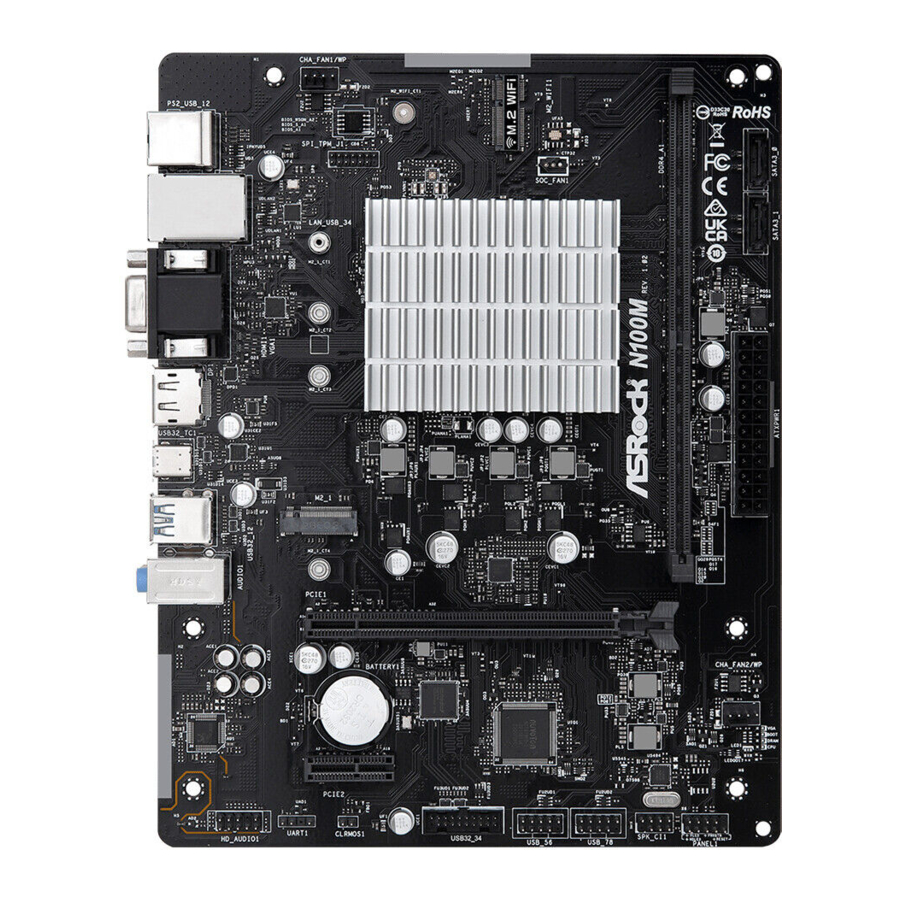
Motherboard Layout

| No. | Description |
| 1 | Chassis/Water Pump Fan Connector (CHA_FAN1/WP) |
| 2 | SPI TPM Header (SPI_TPM_J1) |
| 3 | 288-pin DDR4 DIMM Slot (DDR4_A1) |
| 4 | SATA3 Connector (SATA3_0) |
| 5 | SATA3 Connector (SATA3_1) |
| 6 | ATX Power Connector (ATXPWR1) |
| 7 | Chassis/Water Pump Fan Connector (CHA_FAN2/WP) |
| 8 | Post Status Checker (PSC) |
| 9 | System Panel Header (PANEL1) |
| 10 | Chassis Intrusion and Speaker Header (SPK_CI1) |
| 11 | USB 2.0 Header (USB_78) |
| 12 | USB 2.0 Header (USB_56) |
| 13 | USB 3.2 Gen1 Header (USB32_34) |
| 14 | Clear CMOS Jumper (CLRMOS1) |
| 15 | Front Panel Audio Header (HD_AUDIO1) |
I/O Panel

| No. | Description |
| 1 | USB 2.0 Ports (USB_12) |
| 2 | LAN RJ-45 Port* |
| 3 | D-Sub Port |
| 4 | Line In (Light Blue)** |
| 5 | Front Speaker (Lime)** |
| 6 | Microphone (Pink)** |
| 7 | USB 3.2 Gen1 Type-A Ports (USB32_12) |
| 8 | USB 3.2 Gen2 Type-C Port (USB32_TC1) |
| 9 | DisplayPort 1.4 |
| 10 | HDMI Port |
| 11 | USB 2.0 Ports (USB_34) |
| 12 | PS/2 Mouse/Keyboard Port |
* There are two LEDs on the LAN port. Please refer to the table below for the LAN port LED indications.
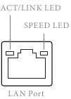
| Activity/Link LED | |
| Status Description | |
| Off | No Link |
| Blinking | Data Activity |
| On | Link |
| Speed LED | |
| Status | Description |
| Off | 10Mbps connection |
| Orange | 100Mbps connection |
| Green | 1Gbps connection |
** Function of the Audio Ports in 7.1-channel Configuration:
| Port | Function |
| Light Blue (Rear panel) | Rear Speaker Out |
| Lime (Rear panel) | Front Speaker Out |
| Pink (Rear panel) | Central /Subwoofer Speaker Out |
| Lime (Front panel) | Side Speaker Out |
Block Diagram

Installation
This is a Micro ATX form factor motherboard. Before you install the motherboard, study the configuration of your chassis to ensure that the motherboard fits into it.
Pre-installation Precautions
Take note of the following precautions before you install motherboard components or change any motherboard settings.
- Make sure to unplug the power cord before installing or removing the motherboard components. Failure to do so may cause physical injuries and damages to motherboard components.
- In order to avoid damage from static electricity to the motherboard's components, NEVER place your motherboard directly on a carpet. Also remember to use a grounded wrist strap or touch a safety grounded object before you handle the components.
- Hold components by the edges and do not touch the ICs.
- Whenever you uninstall any components, place them on a grounded anti-static pad or in the bag that comes with the components.
- When placing screws to secure the motherboard to the chassis, please do not overtighten the screws! Doing so may damage the motherboard.
Installing Memory Module (DIMM)
This motherboard provides a 288-pin DDR4 (Double Data Rate 4) DIMM slot.
- It is not allowed to install a DDR, DDR2 or DDR3 memory module into a DDR4 slot; otherwise, this motherboard and DIMM may be damaged.
- The DIMM only fits in one correct orientation. It will cause permanent damage to the motherboard and the DIMM if you force the DIMM into the slot at incorrect orientation.

Connecting the Front Panel Header

Installing the I/O Panel Shield

Installing the Motherboard

Installing SATA Drives


Installing a Graphics Card

Expansion Slots (PCIe Slots)
There are 2 PCI Express slots on the motherboard.
Before installing an expansion card, please make sure that the power supply is switched off or the power cord is unplugged. Please read the documentation of the expansion card and make necessary hardware settings for the card before you start the installation.
PCIe slots:
PCIE1 (PCIe 3.0 x16 slot) is used for PCIe x2 lane width graphics cards.
PCIE2 (PCIe 3.0 x1 slot) is used for PCIe x1 lane width cards.
Connecting Peripheral Devices

Connecting the Power Connectors

Power On

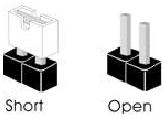
Jumpers Setup
The illustration shows how jumpers are setup. When the jumper cap is placed on the pins, the jumper is "Short". If no jumper cap is placed on the pins, the jumper is "Open".
Clear CMOS Jumper
(CLRMOS1) (see "Motherboard Layout", No. 14)
CLRMOS1 allows you to clear the data in CMOS. The data in CMOS includes system setup information such as system password, date, time, and system setup parameters. To clear and reset the system parameters to default setup, please turn off the computer and unplug the power cord, then use a jumper cap to short the pins on CLRMOS1 for 3 seconds. Please remember to remove the jumper cap after clearing the CMOS. If you need to clear the CMOS when you just finish updating the BIOS, you must boot up the system first, and then shut it down before you do the clear-CMOS action.

Onboard Headers and Connectors
Onboard headers and connectors are NOT jumpers. Do NOT place jumper caps over these headers and connectors. Placing jumper caps over the headers and connectors will cause permanent damage to the motherboard.
System Panel Header
(9-pin PANEL1) (see "Motherboard Layout", No. 9)
Connect the power button, reset button and system status indicator on the chassis to this header according to the pin assignments below. Note the positive and negative pins before connecting the cables.

PWRBTN (Power Button):
Connect to the power button on the chassis front panel. You may configure the way to turn off your system using the power button.
RESET (Reset Button):
Connect to the reset button on the chassis front panel. Press the reset button to restart the computer if the computer freezes and fails to perform a normal restart.
PLED (System Power LED):
Connect to the power status indicator on the chassis front panel. The LED is on when the system is operating. The LED keeps blinking when the system is in S1/S3 sleep state. The LED is off when the system is in S4 sleep state or powered off (S5).
HDLED (Hard Drive Activity LED):
Connect to the hard drive activity LED on the chassis front panel. The LED is on when the hard drive is reading or writing data.
The front panel design may differ by chassis. A front panel module mainly consists of power button, reset button, power LED, hard drive activity LED, speaker and etc. When connecting your chassis front panel module to this header, make sure the wire assignments and the pin assignments are matched correctly.
Chassis Intrusion and Speaker Header
(7-pin SPK_CI1) (see "Motherboard Layout", No. 10)
Please connect the chassis intrusion and the chassis speaker to this header.

Serial ATA3 Connectors
Vertical:
(SATA3_0) (see "Motherboard Layout", No. 4)
(SATA3_1) (see "Motherboard Layout", No. 5)
These two SATA3 connectors support SATA data cables for internal storage devices with up to 6.0 Gb/s data transfer rate.

USB 2.0 Headers
(9-pin USB_56) (see "Motherboard Layout", No. 12)
(9-pin USB_78) (see "Motherboard Layout", No. 11)
There are two headers on this motherboard. Each USB 2.0 header can support two ports.

USB 3.2 Gen1 Header
(19-pin USB32_34) (see "Motherboard Layout", No. 13)
There is one header on this motherboard. This USB 3.2 Gen1 header can support two ports
 .
.
Front Panel Audio Header
(9-pin HD_AUDIO1) (see "Motherboard Layout", No. 15)
This header is for connecting audio devices to the front audio panel.

High Definition Audio supports Jack Sensing, but the panel wire on the chassis must support HDA to function correctly. Please follow the instructions in our manual and chassis manual to install your system.
Chassis/Water Pump Fan Connectors
(4-pin CHA_FAN1/WP) (see "Motherboard Layout", No. 1)
(4-pin CHA_FAN2/WP) (see "Motherboard Layout", No. 7)
This motherboard provides two 4-Pin water cooling chassis fan connectors. If you plan to connect a 3-Pin chassis water cooler fan, please connect it to Pin 1-3.

ATX Power Connector
(24-pin ATXPWR1) (see "Motherboard Layout", No. 6)
This motherboard provides a 24-pin ATX power connector. To use a 20-pin ATX power supply, please plug it along Pin 1 and Pin 13.

SPI TPM Header
(13-pin SPI_TPM_J1) (see "Motherboard Layout", No. 2)
This connector supports SPI Trusted Platform Module (TPM) system, which can securely store keys, digital certificates, passwords, and data. A TPM system also helps enhance network security, protects digital identities, and ensures platform integrity.

Post Status Checker
Post Status Checker (PSC) diagnoses the computer when users power on the machine. It emits a red light to indicate whether the CPU, memory, VGA or storage is dysfunctional. The lights go off if the four mentioned above are functioning normally.

Intel® CNVi (Integrated WiFi/BT) Installation Guide
The M.2 is a small size and versatile card edge connector that aims to replace mPCIe and mSATA. The M.2 Socket (Key E) supports type 2230 Intel® CNVi (Integrated WiFi/BT).
* M.2 PCI Express module is not supported
 Before you install Intel® Integrated Connectivity (CNVi) module, be sure to turn off the AC power.
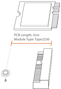
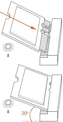
Installing the WiFi/BT module or Intel® CNVi (Integrated WiFi/BT)
- Prepare a type 2230 Intel® CNVi (Integrated WiFi/BT) and the screw.
![]()
- Find the nut location to be used.
![]()
- Gently insert the Intel® CNVi (Integrated WiFi/BT) into the M.2 slot. Please be aware that the module only fits in one orientation.
![]()
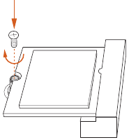
- Tighten the screw with a screwdriver to secure the module into place.
Please do not overtighten the screw as this might damage the module.
![]()

M.2 SSD Module Installation Guide (M2_1)
The M.2 is a small size and versatile card edge connector that aims to replace mPCIe and mSATA. The M.2 Socket (M2_1, Key M) supports type 2242/2260/2280 PCIe Gen3x2 (16 Gb/s) mode.
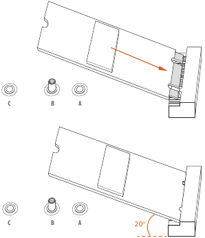
Installing the M.2 SSD Module
- Prepare a M.2 SSD module and the screw.

- Depending on the PCB type and length of your M.2 SSD module, find the corresponding nut location to be used.

No. 1 2 3 Nut Location A B C PCB Length 4.2cm 6cm 8cm Module Type Type2242 Type2260 Type 2280 - Move the standoff based on the module type and length. The standoff is placed at the nut location C by default. Skip Step 3 and 4 and go straight to Step 5 if you are going to use the default nut. Otherwise, release the standoff by hand.

- Peel off the yellow protective film on the nut to be used. Hand tighten the standoff into the desired nut location on the motherboard.

- Align and gently insert the M.2 SSD module into the M.2 slot. Please be aware that the M.2 SSD module only fits in one orientation.
![]()
- Tighten the screw with a screwdriver to secure the module into place.
Please do not overtighten the screw as this might damage the module.


For the latest updates of M.2 SSD module support list, please visit our website for details: http://www.asrock.com
Contact Information
If you need to contact ASRock or want to know more about ASRock, you're welcome to visit ASRock's website at http://www.asrock.com; or you may contact your dealer for further information. For technical questions, please submit a support request form at https://event.asrock.com/tsd.asp
ASRock Incorporation
e-mail: info@asrock.com.tw
ASRock EUROPE B.V.
e-mail: sales@asrock.nl
ASRock America, Inc.
e-mail: sales@asrockamerica.com
Documents / Resources
References
Download manual
Here you can download full pdf version of manual, it may contain additional safety instructions, warranty information, FCC rules, etc.
Advertisement


Need help?
Do you have a question about the N100M and is the answer not in the manual?
Questions and answers