Table of Contents
Advertisement
Advertisement
Table of Contents

Related Manuals for ASROCK 990FX Extreme6


Summary of Contents for ASROCK 990FX Extreme6
- Page 1 990FX Extreme6 990FX Extreme6 9 9 0 F X E x t r e m e 6 9 9 0 F X E x t r e m e 6...
-
Page 2: Copyright Notice
(including damages for loss of proits, loss of business, loss of data, interruption of business and the like), even if ASRock has been advised of the possibility of such damages arising from any defect or error in the documentation or product. - Page 3 Manufactured under license under U.S. Patent Nos: 5,956,674; 5,974,380; 6,487,535; 7,003,467 & other U.S. and worldwide patents issued & pending. DTS, the Symbol, & DTS and the Symbol together is a registered trademark & DTS Connect, DTS Interactive, DTS Neo:PC are trademarks of DTS, Inc. Product includes sotware. ©...
-
Page 4: Table Of Contents
Contents Chapter 1 Introduction Package Contents Speciications Motherboard Layout I/O Panel Chapter 2 Installation Installing the CPU Installing the CPU Fan and Heatsink Installing Memory Modules (DIMM) Expansion Slots (PCI Express Slots) Jumpers Setup Onboard Headers and Connectors and Quad SLI Operation Guide 2.7.1 Installing Two SLI -Ready Graphics Cards... - Page 5 Installing Drivers ASRock EXTREME TUNING UTILITY Start8 Chapter 4 UEFI SETUP UTILITY Introduction 4.1.1 UEFI Menu Bar 4.1.2 Navigation Keys Main Screen OC Tweaker Screen Advanced Screen 4.4.1 CPU Coniguration 4.4.2 North Bridge Coniguration 4.4.3 South Bridge Coniguration 4.4.4 Storage Coniguration 4.4.5 Super IO Coniguration...
-
Page 6: Chapter 1 Introduction
If you require technical support related to this motherboard, please visit our website for speciic information about the model you are using. You may ind the latest VGA cards and CPU support list on ASRock’s website as well. ASRock website http://www.asrock.com. -
Page 7: Speciications
1.2 Speciications • ATX Form Factor Platform • Nichicon 12K Platinum Caps (100% Japan made high quality conductive polymer capacitors) • High Density Glass Fabric PCB • Supports Socket AM3+ processors • Supports Socket AM3 processors: AMD Phenom II X6 / X4 / X3 / X2 (except 920 / 940) / Athlon II X4 / X3 / X2 / Sempron processors • Supports 8-Core CPU... - Page 8 Rear Panel • 1 x PS/2 Keyboard Port • 1 x Optical SPDIF Out Port • 6 x USB 2.0 Ports (Supports ESD Protection (ASRock Full Spike Protection)) • 4 x USB 3.0 Ports (ASMedia Hub) (Supports ESD Protection (ASRock Full Spike Protection)) • 1 x eSATA3 Connector...
- Page 9 • 1 x Vertical Type A USB 3.0 (Supports ESD Protection (ASRock Full Spike Protection)) • 1 x USB 3.0 Header by Etron EJ188 (Supports 2 USB 3.0 ports) (Supports ESD Protection (ASRock Full Spike Protection)) • 32Mb AMI UEFI Legal BIOS with with GUI support BIOS • Supports “Plug and Play”...
- Page 10 2. Due to the operating system limitation, the actual memory size may be less than 4GB for the reservation for system usage under Windows® 8.1 / 8 / 7. For Windows® 64-bit OS with 64-bit CPU, there is no such limitation. You can use ASRock XFast RAM to utilize the memory that Windows® cannot use.
-
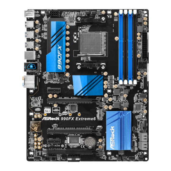
Page 11: Motherboard Layout
USB6_7 USB8_9 USB 2.0 Top: T: USB4 RJ-45 B: USB5 CHA_FAN1 PWR_FAN1 990FX Chipset PCIE1 USB3_7 Vertical Type A USB PCIE2 990FX Extreme6 Purity Sound 2 SB950 PCIE3 Chipset CMOS PCIE4 BATTERY RoHS 32Mb PCIE5 BIOS PLED1 COM1 SLI/XFIRE_PWR1 CHA_FAN3... - Page 12 990FX Extreme6 No. Description Chassis Fan Connector (CHA_FAN2) ATX 12V Power Connector (ATX12V1) CPU Fan Connector (CPU_FAN1) CPU Fan Connector (CPU_FAN2) 2 x 240-pin DDR3 DIMM Slots (DDR3_A1, DDR3_B1) 2 x 240-pin DDR3 DIMM Slots (DDR3_A2, DDR3_B2) ATX Power Connector (ATXPWR1) USB 2.0 Header (USB8_9)
-
Page 13: I/O Panel
1.4 I/O Panel No. Description No. Description PS/2 Mouse Port Line In (Light Blue) USB 2.0 Ports (USB_01) Front Speaker (Lime)** USB 3.0 Ports (USB3_12) Microphone (Pink) USB 3.0 Ports (USB3_34) Optical SPDIF Out Port USB 2.0 Ports (USB23) USB 2.0 Ports (USB_45) LAN RJ-45 Port* eSATA3 Port (ESATA1)*** Central / Bass (Orange) - Page 14 990FX Extreme6 * here are two LEDs on each LAN port. Please refer to the table below for the LAN port LED indications. ACT/LINK LED SPEED LED LAN Port Activity / Link LED Speed LED Status Description Status Description No Link...
-
Page 15: Chapter 2 Installation
Chapter 2 Installation his is an ATX form factor motherboard. Before you install the motherboard, study the coniguration of your chassis to ensure that the motherboard its into it. Pre-installation Precautions Take note of the following precautions before you install motherboard components or change any motherboard settings. -
Page 16: Installing The Cpu
990FX Extreme6 2.1 Installing the CPU Unplug all power cables before installing the CPU. - Page 17 English...
-
Page 18: Installing The Cpu Fan And Heatsink
990FX Extreme6 2.2 Installing the CPU Fan and Heatsink Ater you install the CPU into this motherboard, it is necessary to install a larger heatsink and cooling fan to dissipate heat. You also need to spray thermal grease between the CPU and the heatsink to improve heat dissipation. Make sure that the CPU and the heatsink are securely fastened and in good contact with each other. -
Page 19: Installing Memory Modules (Dimm)
2.3 Installing Memory Modules (DIMM) his motherboard provides four 240-pin DDR3 (Double Data Rate 3) DIMM slots, and supports Dual Channel Memory Technology. 1. For dual channel coniguration, you always need to install identical (the same brand, speed, size and chip-type) DDR3 DIMM pairs. 2. - Page 20 990FX Extreme6...
-
Page 21: Expansion Slots (Pci Express Slots)
2.4 Expansion Slots (PCI Express Slots) here are 5 PCI Express slots on the motherboard. Before installing an expansion card, please make sure that the power supply is switched of or the power cord is unplugged. Please read the documentation of the expansion card and make necessary hardware settings for the card before you start the installation. -
Page 22: Jumpers Setup
990FX Extreme6 2.5 Jumpers Setup he illustration shows how jumpers are setup. When the jumper cap is placed on the pins, the jumper is “Short”. If no jumper cap is placed on the pins, the jumper is “Open”. he illustration shows a 3-pin jumper whose pin1 and pin2 are “Short”... -
Page 23: Onboard Headers And Connectors
2.6 Onboard Headers and Connectors Onboard headers and connectors are NOT jumpers. Do NOT place jumper caps over these headers and connectors. Placing jumper caps over the headers and connectors will cause permanent damage to the motherboard. System Panel Header Connect the power PLED+ PLED-... - Page 24 990FX Extreme6 Power LED Header Please connect the chassis PLED- (3-pin PLED1) power LED to this header PLED+ PLED+ (see p.6, No. 18) to indicate the system’s power status. Serial ATA3 Connectors hese ive SATA3 (SATA3_1: connectors support SATA see p.6, No. 17)
- Page 25 Front Panel Audio Header his header is for PRESENCE# MIC_RET (9-pin HD_AUDIO1) connecting audio devices OUT_RET (see p.6, No. 27) to the front audio panel. O U T 2 _ L J _ S E N S E OUT2_R MIC2_R MIC2_L 1.
- Page 26 990FX Extreme6 CPU Fan Connectors his motherboard pro- FAN_SPEED_CONTROL CPU_FAN_SPEED (4-pin CPU_FAN1) vides a 4-Pin CPU fan +12V (see p.6, No. 3) (Quiet Fan) connector. If you plan to connect a 1 2 3 4 (3-pin CPU_FAN2) 3-Pin CPU fan, please +12V (see p.6, No.
- Page 27 Serial Port Header his COM1 header RRXD1 DDTR#1 DDSR#1 (9-pin COM1) supports a serial port CCTS#1 (see p.6, No. 25) module. RRI#1 RRTS#1 TTXD1 DDCD#1 SPDIF Out Connector Please connect the (2-pin SPDIF_OUT1) SPDIF_OUT connector of SPDIFOUT (see p.6, No. 26) a HDMI VGA card to this header with a cable.
-
Page 28: Sli Tm And Quad Sli Tm Operation Guide
990FX Extreme6 2.7 SLI and Quad SLI Operation Guide ® his motherboard supports NVIDIA and Quad SLI (Scalable Link Interface) technology that allows you to install up to two identical PCI Express x16 ® graphics cards. Currently, NVIDIA and Quad SLI technology supports ®... - Page 29 Step 3 Align and insert the ASRock SLI_ Bridge_2S Card to the goldingers on each graphics card. Make sure the ASRock SLI_ Bridge_2S Card is irmly in place. SLI_Bridge_2S Card ASRock SLI_Bridge_2S Card Step 4 Connect a VGA cable or a DVI cable to the...
-
Page 30: Driver Installation And Setup
990FX Extreme6 2.7.2 Driver Installation and Setup Install the graphics card drivers to your system. Ater that, you can enable the ® Multi-Graphics Processing Unit (GPU) in the NVIDIA nView system tray utility. Please follow the below procedures to enable the multi-GPU. -
Page 31: Tm And Quad Crossfirex
2.8 CrossFireX , 3-Way CrossFireX and Quad CrossFireX Operation Guide his motherboard supports CrossFireX , 3-way CrossFireX and Quad CrossFireX that allows you to install up to three identical PCI Express x16 graphics cards. Currently CrossFireX , 3-way CrossFireX and Quad ®... -
Page 32: Installing Three Crossfirex
990FX Extreme6 Step 3 Connect a VGA cable or a DVI cable to the monitor connector or the DVI connec- tor of the graphics card that is inserted to PCIE2 slot. 2.8.2 Installing Three CrossFireX -Ready Graphics Cards Step 1... -
Page 33: Driver Installation And Setup
2.8.3 Driver Installation and Setup Step 1 Power on your computer and boot into OS. Step 2 Remove the AMD drivers if you have any VGA drivers installed in your system. he Catalyst Uninstaller is an optional download. We recommend using this utility to uninstall any previously installed Catalyst drivers prior to installation. -
Page 34: M.2_Ssd (Ngff) Module Installation Guide
990FX Extreme6 2.9 M.2_SSD (NGFF) Module Installation Guide The M.2, also known as the Next Generation Form Factor (NGFF), is a small size and versatile card edge connector that aims to replace mPCIe and mSATA. The M.2_SSD (NGFF) Socket 3 can accommodate either a M.2 SATA3 6.0 Gb/s module or a M.2 PCI Express module up to Gen 2 x2 (10 Gb/s). - Page 35 Tighten the screw knob to secure the module into place. NUT2 NUT1 M.2_SSD (NGFF) Module Support List PCIe Interface SATA Interface SanDisk SD6PP4M-128G Intel SSDSCKGW080A401/80G SanDisk SD6PP4M-256G For the latest updates of M.2_SSD (NFGG) module support list, please visit our website for details: http://www.asrock.com...
-
Page 36: Chapter 3 Software And Utilities Operation
990FX Extreme6 Chapter 3 Software and Utilities Operation 3.1 Installing Drivers he Support CD that comes with the motherboard contains necessary drivers and useful utilities that enhance the motherboard’s features. Running The Support CD To begin using the support CD, insert the CD into your CD-ROM drive. he CD automatically displays the Main Menu if “AUTORUN”... -
Page 37: Asrock Extreme Tuning Utility
3.2 ASRock EXTREME TUNING UTILITY ASRock Extreme Tuning Utility (AXTU) is an all-in-one tool to ine-tune diferent system functions in a user-friendly interface, which is including Hardware Monitor, Fan Control, Overclocking, OC DNA, IES, XFast RAM and Restart to UEFI. In Hardware Monitor, it shows the major readings of your system. -
Page 38: Hardware Monitor
990FX Extreme6 Hardware Monitor In the Hardware Monitor section, it shows the major readings of your system. he main readings include Clock, Fan & Temperature, and Voltage. In Clock, there are CPU speed and CPU ratio. In Fan & Temperature, there are CPU temperature and CPU fan speed. - Page 39 Overclocking In the Overclocking section, there are Clock and Voltage chapters for users to adjust settings and pursuit optimal system performance. You are able to ine-tune the CPU ratio, CPU frequency, and respective voltages by clicking the “+/-” at the display panel.
- Page 40 990FX Extreme6 Featuring an advanced proprietary hardware and sotware design, Intelligent Energy Saving is a revolutionary technology that delivers unparalleled power savings. he voltage regulator can reduce the number of output phases to improve eiciency when the CPU cores are idle. In other words, it is able to provide exceptional power saving and improve power eiciency without sacriicing computing performance.
- Page 41 Restart to UEFI Windows® 8 brings the ultimate boot up experience. he lightning boot up speed makes it hard to access the UEFI setup. Restart to UEFI technology is designed for those requiring frequent UEFI access. It allows users to easily enter the UEFI automatically when turning on the PC next time.
-
Page 42: Start8
3.3.1 Installing Start8 Install Start8, which is located in the folder at the following path of the Support CD: \ ASRock Utility > Start8. 3.3.2 Coniguring Start8 Style Select between the Windows 7 style and Windows 8 style Start Menu. hen select... - Page 43 Conigure Conigure provides coniguration options, including icon sizes, which shortcuts you want Start Menu to display, quick access to recently used apps, the functionality of the power button, and more. Control...
- Page 44 990FX Extreme6 Control lets you conigure what a click on the start button or a press on the Windows key does. Desktop Desktop allows you to disable the hot corners when you are working on the desktop. It also lets you choose whether or not the system boots directly into desktop mode and bypass the Metro user interface.
-
Page 45: Chapter 4 Uefi Setup Utility
Chapter 4 UEFI SETUP UTILITY 4.1 Introduction his section explains how to use the UEFI SETUP UTILITY to conigure your system. You may run the UEFI SETUP UTILITY by pressing <F2> or <Del> right ater you power on the computer, otherwise, the Power-On-Self-Test (POST) will continue with its test routines. -
Page 46: Navigation Keys
990FX Extreme6 4.1.2 Navigation Keys Use < > key or < > key to choose among the selections on the menu bar, and use < > key or < > key to move the cursor up or down to select items, then press <Enter>... -
Page 47: Main Screen
4.2 Main Screen When you enter the UEFI SETUP UTILITY, the Main screen will appear and display the system overview. Active Page on Entry Select the default page when entering the UEFI setup utility. -
Page 48: Oc Tweaker Screen
990FX Extreme6 4.3 OC Tweaker Screen In the OC Tweaker screen, you can set up overclocking features. Because the UEFI sotware is constantly being updated, the following UEFI setup screens and descriptions are for reference purpose only, and they may not exactly match what you see on your screen. -
Page 49: Spread Spectrum
ASRock UCC (Unlock CPU Core) feature simpliies AMD CPU activation. As long as a simple switch of the UEFI option “ASRock UCC”, you can unlock the extra CPU core to enjoy an instant performance boost. When UCC feature is enabled, the dual-core... -
Page 50: Dram Timing Coniguration
990FX Extreme6 CPU Frequency Multiplier For safety and system stability, it is not recommended to adjust the value of this item. CPU Voltage It allows you to adjust the value of CPU voltage. However, for safety and system stability, it is not recommended to adjust the value of this item. -
Page 51: Channel Interleaving
DRAM Timing Control DRAM Slot Use this item to view SPD data. DRAM Timing Control Use this item to control DRAM timing. Power Down Enable Use this item to enable or disable DDR power down mode. Bank Interleaving Interleaving allows memory accesses to be spread out over banks on the same node, or accross nodes, decreasing access contention. - Page 52 990FX Extreme6 CPU Voltage Ofset Conigure the dynamic CPU voltage added to the CPU. NB Voltage Use this to select NB Voltage. he default value is [Auto]. HT Voltage Use this to select HT Voltage. he default value is [Auto].
-
Page 53: Advanced Screen
4.4 Advanced Screen In this section, you may set the conigurations for the following items: CPU Coniguration, North Bridge Coniguration, South Bridge Coniguration, Storage Coniguration, Super IO Coniguration, ACPI Coniguration, USB Coniguration and Trusted Computing. Setting wrong values in this section may cause the system to malfunction. -
Page 54: Cpu Coniguration
990FX Extreme6 4.4.1 CPU Coniguration Cool 'n' Quiet Use this item to enable or disable AMD’s Cool ‘n’ Quiet technology. he default value is [Enabled]. Coniguration options: [Enabled] and [Disabled]. If you install ® Windows 8.1 / 8 / 7 and want to enable this function, please set this item to [Enabled]. - Page 55 CPU Thermal Throttle Use this item to enable CPU internal thermal control mechanism to keep the CPU from overheated. he default value is [Auto].
-
Page 56: North Bridge Coniguration
990FX Extreme6 4.4.2 North Bridge Coniguration IOMMU Use this to enable or disable IOMMU. he default value of this feature is [Disabled]. -
Page 57: South Bridge Coniguration
4.4.3 South Bridge Coniguration Onboard HD Audio Enable/disable onboard HD audio. Set to Auto to enable onboard HD audio and automatically disable it when a sound card is installed. Front Panel Enable/disable front panel HD audio. Onboard LAN Enable or disable the onboard network interface controller. Good Night LED By enabling Good Night LED, the Power/HDD LEDs will be switched of when the system is on. -
Page 58: Storage Coniguration
990FX Extreme6 4.4.4 Storage Coniguration SATA Controller(s) Enable/disable the SATA controllers. SATA Mode IDE: For better compatibility. AHCI: Supports new features that improve performance. RAID: Combine multiple disk drives into a logical unit. If you set this item to RAID mode, it is suggested to install SATA ODD driver on SATA3_5 or eSATA3 port. -
Page 59: Aggressive Link Power Management
If you want to build RAID on SATA3_5 and eSATA3 ports, please disable this item. Aggressive Link Power Management Aggressive Link Power Management allows SATA devices to enter a low power state during periods of inactivity to save power. It is only supported by AHCI mode. Hard Disk S.M.A.R.T. -
Page 60: Super Io Coniguration
990FX Extreme6 4.4.5 Super IO Coniguration Serial Port Enable or disable the Serial port. Serial Port Address Select the address of the Serial port. Infrared Port Enable or disable the Infrared port. -
Page 61: Acpi Coniguration
4.4.6 ACPI Coniguration Suspend to RAM Select disable for ACPI suspend type S1. It is recommended to select auto for ACPI S3 power saving. Check Ready Bit Enable to enter the operating system ater S3 only when the hard disk is ready, this is recommended for better system stability. - Page 62 990FX Extreme6 Ring-In Power On Allow the system to be waked up by onboard COM port modem Ring-In signals. RTC Alarm Power On Allow the system to be waked up by the real time clock alarm. Set it to By OS to let it be handled by your operating system.
-
Page 63: Usb Coniguration
4.4.7 USB Coniguration USB Controller Enable or disable all the USB 2.0 ports. USB 3.0 Controller Enable or disable all the USB 3.0 ports. Legacy USB Support Enable or disable Legacy OS Support for USB 2.0 devices. If you encounter USB compatibility issues it is recommended to disable legacy USB support. -
Page 64: Trusted Computing
990FX Extreme6 4.4.8 Trusted Computing Security Device Support Enable to activate Trusted Platform Module (TPM) security for your hard disk drives. -
Page 65: Tools
In order to prevent users from bypassing OMG, guest accounts without permission to modify the system time are required. UEFI Tech Service Contact ASRock Tech Service if you are having trouble with your PC. Please setup network coniguration before using UEFI Tech Service. Easy RAID Installer Easy RAID Installer helps you to copy the RAID driver from the support CD to your USB storage device. -
Page 66: Network Coniguration
Save UEFI iles in your USB storage device and run Instant Flash to update your UEFI. Internet Flash ASRock Internet Flash downloads and updates the latest UEFI irmware version from our servers for you. Please setup network coniguration before using Internet Flash. - Page 67 Dehumidiier Function If Dehumidiier Function is enabled, the computer will power on automatically to dehumidify the system ater entering S4/S5 state. Dehumidiier Period Conigure the period of time until the computer powers on and enables Dehumidiier ater entering S4/S5 state. Dehumidiier Duration Conigure the duration of the dehumidifying process before it returns to S4/S5 state.
-
Page 68: Hardware Health Event Monitoring Screen
990FX Extreme6 4.6 Hardware Health Event Monitoring Screen his section allows you to monitor the status of the hardware on your system, including the parameters of the CPU temperature, motherboard temperature, fan speed and voltage. CPU Fan 1 & 2 Setting his allows you to set the CPU fan 1 &... -
Page 69: Boot Screen
4.7 Boot Screen his section displays the available devices on your system for you to conigure the boot settings and the boot priority. Fast Boot Fast Boot minimizes your computer's boot time. In fast mode you may not boot from an USB storage device. Ultra Fast mode is only supported by Windows 8.1 / 8 and the VBIOS must support UEFI GOP if you are using an external graphics card. - Page 70 990FX Extreme6 AddOn ROM Display Enable AddOn ROM Display to see the AddOn ROM messages or conigure the AddOn ROM if you've enabled Full Screen Logo. Disable for faster boot speed. Boot Failure Guard If the computer fails to boot for a number of times the system automatically restores the default settings.
-
Page 71: Launch Storage Oprom Policy
CSM (Compatibility Support Module) Enable to launch the Compatibility Support Module. Please do not disable unless you’re running a WHCK test. If you are using Windows 8.1 / 8 64-bit and all of your devices support UEFI, you may also disable CSM for faster boot speed. Launch PXE OpROM Policy Select UEFI only to run those that support UEFI option ROM only. -
Page 72: Security Screen
990FX Extreme6 4.8 Security Screen In this section you may set or change the supervisor/user password for the system. You may also clear the user password. Supervisor Password Set or change the password for the administrator account. Only the administrator has authority to change the settings in the UEFI Setup Utility. -
Page 73: Exit Screen
4.9 Exit Screen Save Changes and Exit When you select this option the following message, “Save coniguration changes and exit setup?” will pop out. Select [OK] to save changes and exit the UEFI SETUP UTILITY. Discard Changes and Exit When you select this option the following message, “Discard changes and exit setup?”... -
Page 74: Contact Information
990FX Extreme6 Contact Information If you need to contact ASRock or want to know more about ASRock, you’re welcome to visit ASRock’s website at http://www.asrock.com; or you may contact your dealer for further information. For technical questions, please submit a support request form at http://www.asrock.com/support/tsd.asp...
Need help?
Do you have a question about the 990FX Extreme6 and is the answer not in the manual?
Questions and answers