Advertisement
- 1 Introduction
-
2
Installation
- 2.1 Pre-installation Precautions
- 2.2 Installing the CPU
- 2.3 Installing the CPU Fan and Heatsink
- 2.4 Installing Memory Modules (DIMM)
- 2.5 Connecting the Front Panel Header
- 2.6 Installing the I/O Panel Shield
- 2.7 Installing the Motherboard
- 2.8 Installing SATA Drives
- 2.9 Installing a Graphics Card
- 2.10 Connecting Peripheral Devices
- 2.11 Connecting the Power Connectors
- 2.12 Power On
- 2.13 Jumpers Setup
- 2.14 Onboard Headers and Connectors
- 2.15 Smart Switches
- 2.16 Post Status Checker
- 2.17 M.2 WiFi/BT PCIe WiFi Module Installation Guide
- 2.18 M.2 SSD Module Installation Guide (M2_1)
- 2.19 M.2 SSD Module Installation Guide (M2_2)
- 3 Contact Information
- 4 Documents / Resources
Introduction
 Because the motherboard specifications and the BIOS software might be updated, the content of this documentation will be subject to change without notice. In case any modifications of this documentation occur, the updated version will be available on ASRock's website without further notice. If you require technical support related to this motherboard, please visit our website for specific information about the model you are using. You may find the latest VGA cards and CPU support list on ASRock's website as well. ASRock website http://www.asrock.com.
Package Contents
- ASRock A620M-HDV/M.2 Motherboard (Micro ATX Form Factor)
- ASRock A620M-HDV/M.2 User Manual
- 1 x I/O Shield
- 2 x Serial ATA (SATA) Data Cables (Optional)
- 3 x Screws for M.2 Sockets (Optional)
Specifications
| Platform |
|
| CPU |
|
| Chipset |
|
| Memory |
|
| Expansion Slot | CPU:
|
| Graphics |
|
| Audio |
|
| LAN |
|
| USB |
|
| Rear Panel I/O |
|
| Storage | CPU:
|
| RAID |
|
| Connector |
** CHA_FAN1~3/WP support the fan power up to 2A (24W). ** CHA_FAN1~3/WP can auto detect if 3-pin or 4-pin fan is in use. |
| BIOS Feature |
|
| OS |
|
| Certifications |
|
* For detailed product information, please visit our website: http://www.asrock.com
 Please realize that there is a certain risk involved with overclocking, including adjusting the setting in the BIOS, applying Untied Overclocking Technology, or using third-party overclocking tools. Overclocking may affect your system's stability, or even cause damage to the components and devices of your system. It should be done at your own risk and expense. We are not responsible for possible damage caused by overclocking.
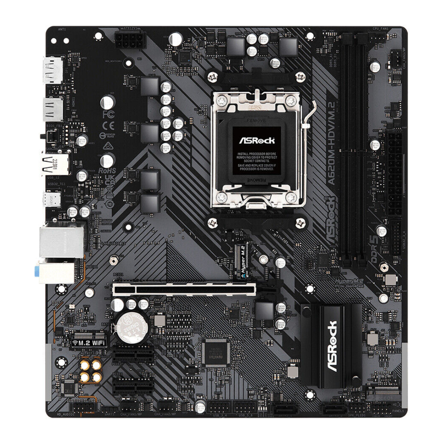
Motherboard Layout

| No. | Description |
| 1 | ATX 12V Power Connector (ATX12V1) |
| 2 | 2 x 288-pin DDR5 DIMM Slots (DDR5_A1, DDR5_B1) |
| 3 | CPU Fan Connector (CPU_FAN1) |
| 4 | Chassis/Water Pump Fan Connector (CHA_FAN3/WP) |
| 5 | ATX Power Connector (ATXPWR1) |
| 6 | USB 3.2 Gen1 Header (USB32_3_4) |
| 7 | Clear CMOS Jumper (CLRCMOS1) |
| 8 | System Panel Header (PANEL1) |
| 9 | Power LED and Speaker Header (SPK_PLED1) |
| 10 | SATA3 Connector (SATA3_2) |
| 11 | SATA3 Connector (SATA3_1) |
| 12 | Post Status Checker (PSC) |
| 13 | USB 2.0 Header (USB_5_6) |
| 14 | USB 2.0 Header (USB_3_4) |
| 15 | Chassis/Water Pump Fan Connector (CHA_FAN2/WP) |
| 16 | Chassis/Water Pump Fan Connector (CHA_FAN1/WP) |
| 17 | Front Panel Audio Header (HD_AUDIO1) |
I/O Panel

| No. | Description | No. | Description |
| 1 | LAN RJ-45 Port* | 6 | USB 3.2 Gen1 Type-C Port (UB32_TC1) |
| 2 | Line In (Light Blue)** | 7 | USB 2.0 Ports (USB_12) |
| 3 | Front Speaker (Lime)** | 8 | BIOS Flashback Button |
| 4 | Microphone (Pink)** | 9 | HDMI Port |
| 5 | USB 3.2 Gen1 Type-A Ports (USB32_12) | 10 | DisplayPort 1.4 |
* There are two LEDs on each LAN port. Please refer to the table below for the LAN port LED indications.

| Activity / Link LED | Speed LED | ||
| Status Description | Status | Description | |
| Off | No Link | Off | 10Mbps connection |
| Blinking | Data Activity | Orange | 100Mbps connection |
| On | Link | Green | 1Gbps connection |
** Function of the Audio Ports in 7.1-channel Configuration:
| Port | Function |
| Light Blue (Rear panel) | Rear Speaker Out |
| Lime (Rear panel) | Front Speaker Out |
| Pink (Rear panel) | Central /Subwoofer Speaker Out |
| Lime (Front panel) | Side Speaker Out |
Block Diagram

Installation
This is a Micro ATX form factor motherboard. Before you install the motherboard, study the configuration of your chassis to ensure that the motherboard fits into it.
Pre-installation Precautions
Take note of the following precautions before you install motherboard components or change any motherboard settings.
- Make sure to unplug the power cord before installing or removing the motherboard components. Failure to do so may cause physical injuries and damages to motherboard components.
- In order to avoid damage from static electricity to the motherboard's components, NEVER place your motherboard directly on a carpet. Also remember to use a grounded wrist strap or touch a safety grounded object before you handle the components.
- Hold components by the edges and do not touch the ICs.
- Whenever you uninstall any components, place them on a grounded anti-static pad or in the bag that comes with the components.
- When placing screws to secure the motherboard to the chassis, please do not overtighten the screws! Doing so may damage the motherboard.
Installing the CPU
- Before you insert the 1718-Pin CPU into the socket, please check if the PnP cap is on the socket, if the CPU surface is unclean, or if there are any bent pins in the socket. Do not force to insert the CPU into the socket if above situation is found. Otherwise, the CPU will be seriously damaged.
- Unplug all power cables before installing the CPU.
![]()
Tutorial Video


Turn your CPU to the correct orientation before opening the CPU socket cover.


Carefully place the CPU in as flat as possible. Do not drop it.

Make sure the CPU is aligned with the socket before locking it into place.

Make sure the black cover plate is always in place until it pops off when closing the socket lever.
Please save the cover if the processor is removed. The cover must be placed if you wish to return the motherboard for after service.
Installing the CPU Fan and Heatsink
After you install the CPU into this motherboard, it is necessary to install a larger heatsink and cooling fan to dissipate heat. You also need to spray thermal grease between the CPU and the heatsink to improve heat dissipation. Make sure that the CPU and the heatsink are securely fastened and in good contact with each other.
Please turn off the power or remove the power cord before changing a CPU or heatsink.
Installing the CPU Cooler (Type 1)
 - Step 1")
 - Step 2")
Installing the CPU Cooler (Type 2)
 - Step 1")
 - Step 2")

*The illustrations shown here are for reference purposes only and may not exactly match the model you purchase.
Installing the CPU Cooler (Type 3)
 - Step 1")
 - Step 2")
 - Step 3")
*The illustrations shown here are for reference purposes only and may not exactly match the model you purchase.
Installing Memory Modules (DIMM)
This motherboard provides two 288-pin DDR5 (Double Data Rate 5) DIMM slots, and supports Dual Channel Memory Technology.
- For dual channel configuration, you always need to install identical (the same brand, speed, size and chip-type) DDR5 DIMM pairs.
- It is unable to activate Dual Channel Memory Technology with only one memory module installed.
- It is not allowed to install a DDR, DDR2, DDR3 or DDR4 memory module into a DDR5 slot; otherwise, this motherboard and DIMM may be damaged.
- The DIMM only fits in one correct orientation. It will cause permanent damage to the motherboard and the DIMM if you force the DIMM into the slot at incorrect orientation.
Recommended Memory Configuration

The first boot may take some time.
Please be patient and refer to the following table for booting time.
*It may vary by different setups.
| Memory | 1st boot after clear CMOS |
| 2 x 16GB | 90 sec |
| 2 x 32GB | 150 sec |
")
Connecting the Front Panel Header

Installing the I/O Panel Shield

Installing the Motherboard

Installing SATA Drives


Installing a Graphics Card

Expansion Slots (PCIe Slots)
There are 3 PCI Express slots on the motherboard.
Before installing an expansion card, please make sure that the power supply is switched off or the power cord is unplugged. Please read the documentation of the expansion card and make necessary hardware settings for the card before you start the installation.
PCIe slots:
PCIE1 (PCIe 4.0 x16 slot) is used for PCIe x16 lane width graphics cards.
PCIE2 (PCIe 3.0 x1 slot) is used for PCIe x1 lane width cards.
PCIE3 (PCIe 3.0 x1 slot) is used for PCIe x1 lane width cards.
Connecting Peripheral Devices

Connecting the Power Connectors

Power On

Jumpers Setup
The illustration shows how jumpers are setup. When the jumper cap is placed on the pins, the jumper is "Short". If no jumper cap is placed on the pins, the jumper is "Open".

Clear CMOS Jumper
(CLRCMOS1) ( see Motherboard Layout, No. 7)
CLRCMOS1 allows you to clear the data in CMOS. The data in CMOS includes system setup information such as system password, date, time, and system setup parameters. To clear and reset the system parameters to default setup, please turn off the computer and unplug the power cord, then use a jumper cap to short the pins on CLRCMOS1 for 3 seconds. Please remember to remove the jumper cap after clearing the CMOS. If you need to clear the CMOS when you just finish updating the BIOS, you must boot up the system first, and then shut it down before you do the clear-CMOS action.

Onboard Headers and Connectors
Onboard headers and connectors are NOT jumpers. Do NOT place jumper caps over these headers and connectors. Placing jumper caps over the headers and connectors will cause permanent damage to the motherboard.
System Panel Header
(9-pin PANEL1)
( see Motherboard Layout, No. 8)
Connect the power button, reset button and system status indicator on the chassis to this header according to the pin assignments below. Note the positive and negative pins before connecting the cables.

PWRBTN (Power Button):
Connect to the power button on the chassis front panel. You may configure the way to turn off your system using the power button.
RESET (Reset Button):
Connect to the reset button on the chassis front panel. Press the reset button to restart the computer if the computer freezes and fails to perform a normal restart.
PLED (System Power LED):
Connect to the power status indicator on the chassis front panel. The LED is on when the system is operating. The LED keeps blinking when the system is in S1/S3 sleep state. The LED is off when the system is in S4 sleep state or powered off (S5).
HDLED (Hard Drive Activity LED):
Connect to the hard drive activity LED on the chassis front panel. The LED is on when the hard drive is reading or writing data.
The front panel design may differ by chassis. A front panel module mainly consists of power button, reset button, power LED, hard drive activity LED, speaker and etc. When connecting your chassis front panel module to this header, make sure the wire assignments and the pin assignments are matched correctly.
Power LED and Speaker Header
(7-pin SPK_PLED1)
( see Motherboard Layout, No. 9)
Please connect the chassis power LED and the chassis speaker to this header.

Serial ATA3 Connectors
Vertical:
(SATA3_1) ( see Motherboard Layout, No. 11)
(SATA3_2) ( see Motherboard Layout, No. 10)
These two SATA3 connectors support SATA data cables for internal storage devices with up to 6.0 Gb/s data transfer rate.

USB 2.0 Headers
(9-pin USB_3_4) ( see Motherboard Layout, No. 14)
(9-pin USB_5_6) ( see Motherboard Layout, No. 13)
There are two headers on this motherboard. Each USB 2.0 header can support two ports.

USB 3.2 Gen1 Header
(19-pin USB32_3_4) ( see Motherboard Layout, No. 6)
There is one header on this motherboard. This USB 3.2 Gen1 header can support two ports.

Front Panel Audio Header
(9-pin HD_AUDIO1) ( see Motherboard Layout, No. 17)
This header is for connecting audio devices to the front audio panel.

High Definition Audio supports Jack Sensing, but the panel wire on the chassis must support HDA to function correctly. Please follow the instructions in our manual and chassis manual to install your system.
Chassis/Water Pump Fan Connectors
(4-pin CHA_FAN1/WP) ( see Motherboard Layout, No.16)
(4-pin CHA_FAN2/WP) ( see Motherboard Layout, No. 15)
(4-pin CHA_FAN3/WP) ( see Motherboard Layout, No. 4)
This motherboard provides three 4-Pin water cooling chassis fan connectors. If you plan to connect a 3-Pin chassis water cooler fan, please connect it to Pin 1-3.

CPU Fan Connector
(4-pin CPU_FAN1) ( see Motherboard Layout, No. 3)
This motherboard provides a 4-Pin CPU fan (Quiet Fan) connector. If you plan to connect a 3-Pin CPU fan, please connect it to Pin 1-3.

ATX Power Connector
(24-pin ATXPWR1) ( see Motherboard Layout, No. 5)
This motherboard provides a 24-pin ATX power connector. To use a 20-pin ATX power supply, please plug it along Pin 1 and Pin 13.

ATX 12V Power Connector
(8-pin ATX12V1) ( see Motherboard Layout, No. 1)
This motherboard provides a 8-pin ATX 12V power connector. To use a 4-pin ATX power supply, please plug it along Pin 1 and Pin 5.


*Please make sure that the power cable connected is for the CPU and not the graphics card. Do not plug the PCIe power cable to this connector.
Smart Switches
The motherboard has one smart switch: BIOS Flashback Button, allowing users to flash the BIOS.
BIOS Flashback Button
(BIOS_FB1) (see I/O Panel, No. 8)
BIOS Flashback Button allows users to flash the BIOS.

This motherboard is equipped with AMD USB BIOS Flashback feature that allows you to update BIOS without powering on the system.
Before using the BIOS Flashback function, please suspend BitLocker and any encryption or security relying on the TPM. Make sure that you have already stored and backup-ed the recovery key. If the recovery key is missing while encryption is active, the data will stay encrypted and the system will not boot into the operating system. It is recommended to disable fTPM before updating the BIOS. Otherwise an unpredictable failure may occur.
USB Drive Requirements
The USB drive that is used for the BIOS update feature should meet the following requirements:
- USB 2.0 only
- Capacity up to 32GB
- Must be formatted as FAT16 or FAT32.
Root Directory Files
In the root directory there are two required files:
- BIOSUBU.BIN (required)
- PSPBIOS.IMG (required)
To use the USB BIOS Flashback function, please follow the steps below.
- Download the latest BIOS file and BIOSUBU.BIN file from ASRock's website: http://www.asrock.com.
- Copy the BIOS file to your USB flash drive. Please make sure the file system of your USB flash drive must be formatted as FAT16 or FAT32.
- Extract BIOS file from the zip file.
- Rename the file to "PSPBIOS.IMG". Save it and BIOSUBU.BIN file to the root directory of X: USB flash drive.
- Install the CPU, CPU fan and DRAM on the motherboard. It is recommended to install the CPU fan to CPU_FAN1 connector. Plug the 8-pin ATX 12V power connector and 24-pin ATX power connector to the motherboard. Then turn on the power supply's AC switch.
*There is no need to power on the system. - Then plug your USB drive to the USB BIOS Flashback port.
- Press the BIOS Flashback Switch for about three seconds. Then the system starts BIOS flashing automatically and the LED starts to blink.
- Wait until the LED stops blinking, indicating that BIOS flashing has been completed. This takes around 2 and a half minutes. Then the system restarts and enter BIOS.
*If the LED light turns solid green, this means that the BIOS Flashback is not operating properly. Please turn off the power supply's AC switch to disconnect power for several minutes, and turn it on again.
**If the LED does not light up at all, this means that the BIOS Flashback does not work. Please turn off the power supply's AC switch to disconnect power for several minutes, and turn it on again.
Post Status Checker
Post Status Checker (PSC) diagnoses the computer when users power on the machine. It emits a red light to indicate whether the CPU, memory, VGA or storage is dysfunctional. The lights go off if the four mentioned above are functioning normally.

It is normal for the DRAM status LED to blink during memory training. This indicates the system is working properly.

Tutorial Video
M.2 WiFi/BT PCIe WiFi Module Installation Guide
The M.2 is a small size and versatile card edge connector that aims to replace mPCIe and mSATA. The M.2 Socket (Key E) supports type 2230 WiFi/BT PCIe WiFi module.
* The M.2 socket does not support SATA M.2 SSDs.
Installing the WiFi/BT module
Step 1 Prepare a type 2230 WiFi/BT PCIe WiFi module and the screw.

Step 2 Find the nut location to be used.

Step 3 Gently insert the WiFi/BT PCIe WiFi module into the M.2 slot. Please be aware that the module only fits in one orientation.

Step 4 Tighten the screw with a screwdriver to secure the module into place. Please do not overtighten the screw as this might damage the module.

M.2 SSD Module Installation Guide (M2_1)
The M.2 is a small size and versatile card edge connector that aims to replace mPCIe and mSATA. The Hyper M.2 Socket (M2_1, Key M) supports type 2280 PCIe Gen4x4 (64 Gb/s) mode.
Installing the M.2 SSD Module
Step 1 Prepare a M.2 SSD module and the screw.

Step 2 Depending on the PCB type and length of your M.2 SSD module, find the corresponding nut location to be used.

| No. | 1 |
| Nut Location | A |
| PCB Length | 8cm |
| Module Type | Type 2280 |
Step 3 Align and gently insert the M.2 SSD module into the M.2 slot. Please be aware that the M.2 SSD module only fits in one orientation.

Step 4 Tighten the screw with a screwdriver to secure the module into place. Please do not overtighten the screw as this might damage the module.

For the latest updates of M.2 SSD module support list, please visit our website for details: http://www.asrock.com
M.2 SSD Module Installation Guide (M2_2)
The M.2 is a small size and versatile card edge connector that aims to replace mPCIe and mSATA. The M.2 Socket (M2_2, Key M) supports type 2260/2280 SATA3 6.0 Gb/s & PCIe Gen3x2 (16 Gb/s) modes.
Installing the M.2 SSD Module
Step 1 Prepare a M.2 SSD module and the screw.

Step 2 Depending on the PCB type and length of your M.2 SSD module, find the corresponding nut location to be used.

| No. | 1 | 2 |
| Nut Location | A | B |
| PCB Length | 6cm | 8cm |
Step 3 Move the standoff based on the module type and length. The standoff is placed at the nut location B by default. Skip Step 3 and 4 and go straight to Step 5 if you are going to use the default nut.

Step 4 Peel off the yellow protective film on the nut to be used. Hand tighten the standoff into the desired nut location on the motherboard.

Step 5 Align and gently insert the M.2 SSD module into the M.2 slot. Please be aware that the M.2 SSD module only fits in one orientation.

Step 6 Tighten the screw with a screwdriver to secure the module into place. Please do not overtighten the screw as this might damage the module.

For the latest updates of M.2 SSD module support list, please visit our website for details: http://www.asrock.com
Contact Information
If you need to contact ASRock or want to know more about ASRock, you're welcome to visit ASRock's website at http://www.asrock.com; or you may contact your dealer for further information.
For technical questions, please submit a support request form at https://event.asrock.com/tsd.asp
e-mail: sales@asrockamerica.com
ASRock Incorporation e-mail: info@asrock.com.tw
ASRock EUROPE B.V. e-mail: sales@asrock.nl
Documents / Resources
References
Download manual
Here you can download full pdf version of manual, it may contain additional safety instructions, warranty information, FCC rules, etc.
Advertisement


Need help?
Do you have a question about the A620M HDV/M.2 and is the answer not in the manual?
Questions and answers