
Related Manuals for ASROCK 990FX Extreme9


Summary of Contents for ASROCK 990FX Extreme9
-
Page 1: User Manual
990FX Extreme9 User Manual Version 1.0 Published January 2013 Copyright©2013 ASRock INC. All rights reserved. -
Page 2: Copyright Notice
ASRock. ASRock assumes no responsibility for any errors or omissions that may appear in this manual. With respect to the contents of this manual, ASRock does not provide warranty of any kind, either expressed or implied, including but not limited to the implied warran- ties or conditions of merchantability or fitness for a particular purpose. -
Page 3: Table Of Contents
CrossFireX , 3-Way CrossFireX and Quad CrossFireX Operation Guide ................ 29 Surround Display Information ............ 33 ASRock Smart Remote Installation Guide ......... 34 Jumpers Setup ................36 2.10 Onboard Headers and Connectors ........37 2.11 Smart Switches ................44 2.12 Dr. Debug ................ - Page 4 3. UEFI SETUP UTILITY ..........53 Introduction ................53 3.1.1 UEFI Menu Bar ..............53 3.1.2 Navigation Keys ............... 54 Main Screen ................54 OC Tweaker Screen..............55 Advanced Screen ..............59 3.4.1 CPU Configuration ............60 3.4.2 North Bridge Configuration ..........61 3.4.3 South Bridge Configuration ..........
-
Page 5: Introduction
In case any modifications of this manual occur, the updated ver- sion will be available on ASRock website without further notice. You may find the latest VGA cards and CPU support lists on ASRock website as well. ASRock website http://www.asrock.com... -
Page 6: Specifications
1.2 Specifications Platform - ATX Form Factor - Premium Gold Capacitor design (100% Japan-made high-quality Conductive Polymer Capacitors) - Support for Socket AM3+ processors - Support for Socket AM3 processors: AMD Phenom II X6 / X4 / X3 / X2 (except 920 / 940) / Athlon II X4 / X3 / X2 / Sempron processors - Supports 8-Core CPU - Supports UCC feature (Unlock CPU Core) (see CAUTION 1) - Page 7 - PCIE x1 Gigabit LAN 10/100/1000 Mb/s ® - Intel 82583V - Supports Wake-On-LAN - Supports PXE Rear Panel I/O I/O Panel - 1 x PS/2 Mouse Port - 1 x PS/2 Keyboard Port - 1 x Coaxial SPDIF Out Port - 1 x Optical SPDIF Out Port - 4 x Ready-to-Use USB 2.0 Ports - 4 x Ready-to-Use USB 3.0 Ports...
- Page 8 Certifications - FCC, CE, WHQL - ErP/EuP Ready (ErP/EuP ready power supply is required) * For detailed product information, please visit our website: http://www.asrock.com WARNING Please realize that there is a certain risk involved with overclocking, including adjusting the setting in the BIOS, applying Untied Overclocking Technology, or using third-party overclocking tools.
- Page 9 4GB for the reservation for system usage un- ® ® der Windows 8 / 7 / Vista . For Windows 64-bit OS with 64- bit CPU, there is no such limitation. You can use ASRock XFast ® RAM to utilize the memory that Windows cannot use.
-
Page 10: Unique Features
OS 32-bit CPU. ASRock Instant Boot ASRock Instant Boot allows you to turn on your PC in just a few seconds, provides a much more efficient way to save energy, time, money, and improves system running speed for your sys- tem. - Page 11 ASRock XFast RAM ASRock XFast RAM is a new function that is included into AS- Rock Extreme Tuning Utility (AXTU). It fully utilizes the memory ® space that cannot be used under Windows OS 32-bit CPU.
- Page 12 S4/S5 state. ASRock Easy RAID Installer ASRock Easy RAID Installer can help you to copy the RAID driver from a support CD to your USB storage device. After copying the RAID driver to your USB storage device, please change “SATA Mode”...
- Page 13 CPU, Memory frequency and all related volt- age settings. ASRock Good Night LED ASRock Good Night LED technology can offer you a better en- vironment by extinguishing the unessential LED. By enabling Good Night LED in BIOS, the Power / HDD / LAN LED will be switched off when system is on.
-
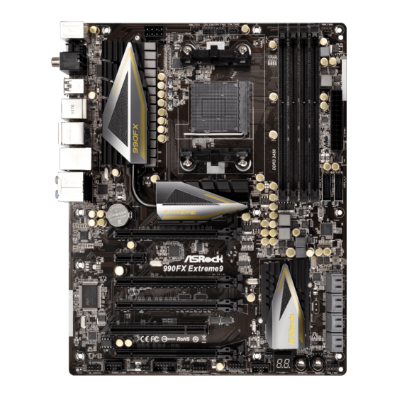
Page 14: Motherboard Layout
USB 2.0 T: USB2 B: USB3 USB 3.0 Top: T: USB2 RJ-45 B: USB3 990FX CMOS Chipset BATTERY PCIE1 AUDIO CODEC PCIE2 990FX Extreme9 PCIE3 SB950 Chipset PCIE4 PCI1 RoHS 32Mb BIOS CHA_FAN3 SPEAKER1 PCIE5 FRONT_1394 COM1 CHA_FAN1 USB4_5 PLED1... -
Page 15: I/O Panel
1.5 I/O Panel PS/2 Mouse Port (Green) Microphone (Pink) Coaxial SPDIF Out Port USB 3.0 Ports (USB3_2_3) USB 2.0 Ports (USB01) IEEE 1394 Port (IEEE 1394) USB 2.0 Port (USB23) *** 14 eSATA3 Connector (ESATA1) LAN RJ-45 Port *** 15 eSATA3 Connector (ESATA2) Side Speaker (Gray) USB 3.0 Ports (USB3_0_1) - Page 16 To enable Multi-Streaming function, you need to connect a front panel audio cable to the front panel audio header. After restarting your computer, you will find “Mixer” tool on your system. Please select “Mixer ToolBox” , click “Enable playback multi-streaming”, and click “ok”. Choose “2CH”, “4CH”, “6CH”, or “8CH”...
-
Page 17: Installation
2. Installation This is an ATX form factor motherboard. Before you install the motherboard, study the configuration of your chassis to ensure that the motherboard fits into it. Pre-installation Precautions Take note of the following precautions before you install motherboard components or change any motherboard settings. -
Page 18: Cpu Installation
2.1 CPU Installation Step 1. Unlock the socket by lifting the lever up to a 90 angle. Step 2. Position the CPU directly above the socket such that the CPU corner with the golden triangle matches the socket corner with a small triangle. Step 3. -
Page 19: Installation Of Memory Modules (Dimm)
2.3 Installation of Memory Modules (DIMM) This motherboard provides four 240-pin DDR3 (Double Data Rate 3) DIMM slots, and supports Dual Channel Memory Technology. For dual channel configuration, you always need to install identical (the same brand, speed, size and chip-type) DDR3 DIMM pair in the slots. -
Page 20: Installing A Dimm
Installing a DIMM Please make sure to disconnect power supply before adding or removing DIMMs or the system components. Step 1. Unlock a DIMM slot by pressing the retaining clips outward. Step 2. Align a DIMM on the slot such that the notch on the DIMM matches the break on the slot. -
Page 21: Expansion Slots (Pci And Pci Express Slots)
PCIE2 (PCIE x1 slot) is used for PCI Express cards with x1 lane width cards, such as ASRock Game Blaster, Gigabit LAN card, SATA card. PCIE3 (PCIE x16 slot) is used for PCI Express x4 lane width graphics cards. -
Page 22: Installing An Expansion Card
Installing an expansion card Step 1. Before installing the expansion card, please make sure that the power supply is switched off or the power cord is unplugged. Please read the documentation of the expansion card and make necessary hardware settings for the card before you start the installation. Step 2. -
Page 23: Sli Tm , 3-Way Sli Tm Tm
2.5 SLI , 3-Way SLI and Quad SLI Operation Guide ® This motherboard supports NVIDIA , 3-Way SLI and Quad SLI (Scalable Link Interface) technology that allows you to install up to three identical PCI Express ® ® x16 graphics cards. Currently, NVIDIA technology supports Windows ®... - Page 24 Step3. Align and insert the ASRock SLI_Bridge_2S Card to the goldfingers on each graphics card. Make sure the ASRock SLI_Bridge_2S Card is firmly in place. ASRock SLI_Bridge_2S Card Step4. Connect a VGA cable or a DVI cable to the monitor connector or the DVI...
- Page 25 (Even the GPU chips version shall be the same.) Each graph- ics card should have two goldfingers for ASRock 3-Way SLI-2S1S Bridge Card connector. Insert one graphics card into PCIE1 slot, another graphics card to PCIE4 slot, and the other graphics card to PCIE5 slot.
-
Page 26: Driver Installation And Setup
2.5.2 Driver Installation and Setup Install the graphics card drivers to your system. After that, you can enable the Multi- ® Graphics Processing Unit (GPU) feature in the NVIDIA nView system tray utility. Please follow the below procedures to enable the multi-GPU feature. ®... - Page 27 ® For Windows Vista / Vista 64-bit / 7 / 7 64-bit / 8 / 8 64-bit OS: (For SLI and Quad SLI mode) A. Click the Start icon on your Windows taskbar. B. From the pop-up menu, select All Programs, and then click NVIDIA Corporation.
- Page 28 ® For Windows Vista / Vista 64-bit / 7 / 7 64-bit / 8 / 8 64-bit OS: (For 3-Way SLI mode) A. Follow steps A to D on page 27. B. From the pop-up menu, select Set SLI and PhysX configuration. In Select a hardware acceleration setting for PhysX item, please select Enabled.
-
Page 29: Crossfirex Operation Guide
2.6 CrossFireX , 3-Way CrossFireX and Quad CrossFireX Operation Guide This motherboard supports CrossFireX , 3-way CrossFireX and Quad CrossFireX feature. CrossFireX technology offers the most advantageous means available of combining multiple high performance Graphics Processing Units (GPU) in a single PC. Combining a range of different operating modes with intelligent software design and an innovative interconnect mechanism, CrossFireX enables the highest possible level of performance and image quality in any 3D ®... - Page 30 Step 2. Connect two Radeon graphics cards by installing CrossFire Bridge on CrossFire Bridge Interconnects on the top of Radeon graphics cards. (CrossFire Bridge is provided with the graphics card you purchase, not bundled with this motherboard. Please refer to your graphics card vendor for details.) CrossFire Bridge Step 3.
-
Page 31: Installing Three Crossfirex
2.6.1.2 Installing Three CrossFireX -Ready Graphics Cards Step 1. Install the identical 3-Way CrossFireX -ready graphics cards that are AMD certified because different types of graphics cards will not work to- gether properly. (Even the GPU chips version shall be the same.) Insert one graphics card into PCIE1 slot, another graphics card to PCIE4 slot, and the other graphics card to PCIE5 slot. - Page 32 2.6.2 Driver Installation and Setup Step 1. Power on your computer and boot into OS. Step 2. Remove the ATI driver if you have any VGA driver installed in your sys- tem. The Catalyst Uninstaller is an optional download. We recommend using this utility to uninstall any previously installed Catalyst drivers prior to installation.
-
Page 33: Surround Display Information
Although you have selected the option “Enable CrossFire ”, the Cross- FireX function may not work actually. Your computer will automatically reboot. After restarting your computer, please confirm whether the option “Enable CrossFire ” in “ATI Catalyst Control Center” is selected or not; if not, please select it again, and then you are able to enjoy the benefit of CrossFireX feature. -
Page 34: Asrock Smart Remote Installation Guide
2.8 ASRock Smart Remote Installation Guide ASRock Smart Remote is only used for ASRock motherboard with CIR header. Please refer to below procedures for the quick installation and usage of ASRock Smart Remote. Step1. Find the CIR header located next to the USB 2.0 header on ASRock... - Page 35 The Multi-Angle CIR Receiver does not support Hot-Plug function. Please install it before you boot the system. * ASRock Smart Remote is only supported by some of ASRock motherboards. Please refer to ASRock website for the motherboard support list: http://www.asrock.com...
-
Page 36: Jumpers Setup
2.9 Jumpers Setup The illustration shows how jumpers are setup. When the jumper cap is placed on pins, the jumper is “Short”. If no jumper cap is placed on pins, the jumper is “Open”. The illustration shows a 3-pin jumper whose pin1 and pin2 are “Short”... -
Page 37: Onboard Headers And Connectors
2.10 Onboard Headers and Connectors Onboard headers and connectors are NOT jumpers. Do NOT place jumper caps over these headers and connectors. Placing jumper caps over the headers and connectors will cause permanent damage of the motherboard! Serial ATA3 Connectors These eight Serial ATA3 (SATA3) connectors support (SATA3_1_2: see p.14, No. -
Page 38: Front Panel Audio Header
(9-pin USB6_7) USB_PWR (see p.14 No. 25) DUMMY USB_PWR USB 3.0 Headers Besides four default USB 3.0 Vbus Vbus ports on the I/O panel, there are (19-pin USB3_4_5) Vbus IntA_P5_SSRX- two USB 3.0 headers on this (see p.14 No. 12) IntA_P4_SSRX- IntA_P5_SSRX+ IntA_P4_SSRX+... -
Page 39: System Panel Header
B. Connect Audio_R (RIN) to OUT2_R and Audio_L (LIN) to OUT2_L. C. Connect Ground (GND) to Ground (GND). D. MIC_RET and OUT_RET are for HD audio panel only. You don’t need to connect them for AC’97 audio panel. E. To activate the front mic. ®... - Page 40 Chassis Speaker Header Please connect the chassis speaker to this header. (4-pin SPEAKER 1) SPEAKER DUMMY (see p.14 No. 19) +5V DUMMY Power LED Header Please connect the chassis power LED to this header to (3-pin PLED1) PLED- indicate system power status. (see p.14 No.
- Page 41 (3-pin CPU_FAN2) +12V (see p.14 No. 5) CPU_FAN_SPEED ATX Power Connector Please connect an ATX power supply to this connector. (24-pin ATXPWR1) (see p.14 No. 10) Though this motherboard provides 24-pin ATX power connector, it can still work if you adopt a traditional 20-pin ATX power supply. To use the 20-pin ATX power supply, please plug your power supply along with Pin 1 and Pin 13.
- Page 42 Serial port Header This COM1 header supports a serial port module. (9-pin COM1) (see p.14 No. 31) Consumer Infrared Module Header This header can be used to connect the remote (4-pin CIR1) IRTX IRRX controller receiver. (see p.14 No. 27) ATX+5VSB...
- Page 43 The Installation Guide of Front USB 3.0 Panel Step 1 Screw the 2.5” HDD/SSD to the Front Step 2 Prepare the bundled Front USB 3.0 Panel, four USB 3.0 Panel with four HDD screws. HDD screws, and six chassis screws. Step 3 Screw the Front USB 3.0 Panel to the Step 4...
-
Page 44: Smart Switches
2.11 Smart Switches The motherboard has three smart switches: power switch, reset switch and clear CMOS switch, allowing users to quickly turn on/off or reset the sytem clear the CMOS values. Power Switch Power Switch is a smart switch, allowing users to quickly turn (PWRBTN) Power on/off the system. -
Page 45: Status Codes
2.12 Dr. Debug Dr. Debug is used to provide code information, which makes troubleshooting even easier. Please see the diagrams below for reading the Dr. Debug codes. Status Code Description Please check if CPU is installed correctly and then clear CMOS. Problem related to memory, VGA card and other devices. -
Page 46: Serial Ata3 (Sata3) Hard Disks Installation
2.13 Serial ATA3 (SATA3) Hard Disks Installation This motherboard adopts AMD SB950 chipset that supports Serial ATA3 (SATA3) hard disks and RAID (RAID 0, RAID 1, RAID 0+1, JBOD and RAID 5) functions. It also adopts ASMedia ASM1061 chipset that supports Serial ATA3 (SATA3) hard disks. -
Page 47: Sata3 Hdd Hot Plug Feature And Operation Operation Guide
* The SATA3 Hot Plug feature might not be supported by the chipset because of its limitation, the SATA3 Hot Plug support information of our motherboard is indicated in the product spec on our website: www.asrock.com 2. Make sure your SATA3 HDD can support Hot Plug function from your dealer or HDD user manual. -
Page 48: How To Hot Plug A Sata3 Hdd
How to Hot Plug a SATA3 HDD: Points of attention, before you process the Hot Plug: Please do follow below instruction sequence to process the Hot Plug, improper procedure will cause the SATA3 HDD damage and data loss. Please connect SATA power cable 1x4-pin Step 1 Connect SATA data cable to Step 2... -
Page 49: Driver Installation Guide
STEP 2: Make a SATA3 Driver Diskette. (Please use an USB floppy or a floppy disk.) A. Insert the ASRock Support CD into your optical drive to boot your system. B. During POST at the beginning of system boot-up, press <F11> key, and then a window for boot devices selection appears. -
Page 50: 64-Bit / 7 / 7 64-Bit / Vista
STEP 3: Use “RAID Installation Guide” to set RAID configuration. Before you start to configure RAID function, you need to check the RAID installation guide in the Support CD for proper configuration. Please refer to the BIOS RAID installation guide part of the document in the following path in the Support CD: .. -
Page 51: 64-Bit / Xp / Xp 64-Bit Without Raid Functions
® 2.18 Installing Windows 8 / 8 64-bit / 7 / 7 64-bit / Vista Vista 64-bit / XP / XP 64-bit Without RAID Functions ® If you want to install Windows 8 / 8 64-bit / 7 / 7 64-bit / Vista / Vista 64-bit / XP / XP 64-bit OS on your SATA3 HDDs without RAID functions, please follow below... -
Page 52: Installing Windows ® 8 / 8 64-Bit / 7 / 7 64-Bit / Vista
® 2.18.2 Installing Windows 8 / 8 64-bit / 7 / 7 64-bit / Vista Vista 64-bit Without RAID Functions ® If you want to install Windows 8 / 8 64-bit / 7 / 7 64-bit / Vista / Vista 64-bit on your SATA3 HDDs without RAID functions, please follow below steps. -
Page 53: Uefi Setup Utility
3. UEFI SETUP UTILITY 3.1 Introduction This section explains how to use the UEFI SETUP UTILITY to configure your system. The UEFI chip on the motherboard stores the UEFI SETUP UTILITY. You may run the UEFI SETUP UTILITY when you start up the computer. Please press <F2>... -
Page 54: Navigation Keys
3.1.2 Navigation Keys Please check the following table for the function description of each navigation key. Navigation Key(s) Function Description Moves cursor left or right to select Screens Moves cursor up or down to select items + / - To change option for the selected items <Tab>... -
Page 55: Oc Tweaker Screen
ASRock UCC ASRock UCC (Unlock CPU Core) feature simplifies AMD CPU activation. As long as a simple switch of the UEFI option “ASRock UCC”, you can unlock the extra CPU core to enjoy an instant performance boost. When UCC feature is enabled, the dual-core or triple-core CPU will boost to the... - Page 56 CPU Active Core Control This allows you to adjust CPU Active Core Control feature. The configura- tion options depend on the CPU core you adopt. The default value is [Dis- abled]. AMD Turbo Core Technology This item appears only when the processor you adopt supports this fea- ture.
- Page 57 HT Bus Speed This feature allows you selecting Hyper-Transport bus speed. Configura- tion options: [200MHz] to [2000MHz]. HT Bus Width This feature allows you selecting Hyper-Transport bus width. Configuration options: [8 Bit] and [16 Bit]. DRAM Timing Configuration DRAM Frequency If [Auto] is selected, the motherboard will detect the memory module(s) inserted and assigns appropriate frequency automatically.
- Page 58 Voltage Configuration CPU Load-line calibration Use this to select CPU Load-line calibration. The default value is [Auto]. DRAM Voltage Use this to select DRAM Voltage. The default value is [Auto]. NB Voltage Use this to select NB Voltage. The default value is [Auto]. HT Voltage Use this to select HT Voltage.
-
Page 59: Advanced Screen
3.4 Advanced Screen In this section, you may set the configurations for the following items: CPU Configu- ration, Nouth Bridge Configuration, South Bridge Configuration, Storage Configura- tion, Super IO Configuration, ACPI Configuration and USB Configuration. Setting wrong values in this section may cause the system to malfunction. -
Page 60: Cpu Configuration
3.4.1 CPU Configuration Cool ‘n’ Quiet Use this item to enable or disable AMD’s Cool ‘n’ Quiet technology. The default value is [Enabled]. Configuration options: [Enabled] and [Disabled]. ® If you install Windows 8 / 7 / Vista and want to enable this function, please set this item to [Enabled]. -
Page 61: North Bridge Configuration
3.4.2 North Bridge Configuration Primary Graphics Adapter This item will switch the PCI Bus scanning order while searching for video card. It allows you to select the type of Primary VGA in case of multiple video controllers. The default value of this feature is [PCI Express]. Con- figuration options: [PCI] and [PCI Express]. -
Page 62: South Bridge Configuration
3.4.3 South Bridge Configuration Onboard HD Audio Select [Auto], [Enabled] or [Disabled] for the onboard HD Audio feature. If you select [Auto], the onboard HD Audio will be disabled when PCI Sound Card is plugged. Front Panel Select [Auto] or [Disabled] for the onboard HD Audio Front Panel. Onboard LAN This allows you to enable or disable the onboard LAN feature. -
Page 63: Storage Configuration
3.4.4 Storage Configuration SATA Controller This item is for SATA3_1 to SATA3_6 ports. Use this item to enable or dis- able the “SATA Controller” feature. SATA Mode This item is for SATA3_1 to SATA3_6 ports.Use this item to adjust SATA Mode. - Page 64 ASMedia SATA3 Mode This item is for SATA3_A1 and SATA3_A2 ports. Use this item to adjust the “ASMedia SATA3 Mode” feature. Configuration options: [Disabled], [IDE Mode] and [AHCI Mode]. The default value is [AHCI Mode]. SATA Boot ROM Use this to enable or disable Onboard ASMedia SATA3 Option ROM. If Option ROM is disabled, UEFI cannot use the SATA device to connect to ASMedia SATA3 controller as Boot Device.
-
Page 65: Super Io Configuration
3.4.5 Super IO Configuration Serial Port Use this item to enable or disable the onboard serial port. Serial Port Address Use this item to set the address for the onboard serial port. Configuration options: [3F8h / IRQ4] and [3E8h / IRQ4]. Infrared Port Use this item to enable or disable the onboard infrared port. -
Page 66: Acpi Configuration
3.4.6 ACPI Configuration Suspend to RAM Use this item to select whether to auto-detect or disable the Suspend-to- RAM feature. Select [Auto] will enable this feature if the OS supports it. Check Ready Bit Use this item to enable or disable the feature Check Ready Bit. ACPI HPET table Use this item to enable or disable ACPI HPET Table. - Page 67 USB Phy Power Down Use this item to enable the USB PHY to power down in S4/S5 state. USB Keyboard/Remote Power On Use this item to enable or disable the system to wake from S5 using USB Keyboard/Remote. USB Mouse Power On Use this item to enable or disable the system to wake from S5 using USB Mouse.
-
Page 68: Usb Configuration
3.4.7 USB Configuration USB 2.0 Controller Use this item to enable or disable the use of USB 2.0 controller. USB 3.0 Controller Use this item to enable or disable the use of USB 3.0 controller. Legacy USB Support Use this option to select legacy support for USB devices. There are four confi guration options: [Enabled], [Disabled], [Auto] and [UEFI Setup Only]. -
Page 69: Tool
3.5 Tool System Browser System Browser can let you easily check your current system configura- tion in UEFI setup. OMG (Online Management Guard) Administrators are able to establish an internet curfew or restrict internet access at specified times via OMG. You may schedule the starting and ending hours of internet access granted to other users. - Page 70 Internet Flash Internet Flash searches for available UEFI firmware updates from our servers. In other words, the system can auto-detect the latest UEFI from our servers and flash them without entering Windows OS. Network Configuration Internet Setting Use this item to set up the internet connection mode. Configuration options: [DHCP (Auto IP)] and [PPPOE].
- Page 71 Would you like to save current setting user defaults? In this option, you are allowed to load and save three user defaults according to your own requirements.
-
Page 72: Hardware Health Event Monitoring Screen
3.6 Hardware Health Event Monitoring Screen In this section, it allows you to monitor the status of the hardware on your system, including the parameters of the CPU temperature, motherboard temperature, CPU fan speed, chassis fan speed, and the critical voltage. CPU Fan 1 &... -
Page 73: Boot Screen
3.7 Boot Screen In this section, it will display the available devices on your system for you to config- ure the boot settings and the boot priority. Fast Boot Fast Boot minimizes your computer’s boot time. There are three con- figuration options: [Disabled], [Fast] and [Ultra Fast]. - Page 74 Full Screen Logo Use this item to enable or disable OEM Logo. The default value is [En- abled]. AddOn ROM Display Use this option to adjust AddOn ROM Display. If you enable the option “Full Screen Logo” but you want to see the AddOn ROM information when the system boots, please select [Enabled].
-
Page 75: Security Screen
3.8 Security Screen In this section, you may set or change the supervisor/user password for the system. For the user password, you may also clear it. Secure Boot Use this to enable or disable Secure Boot. The default value is [Disabled]. -
Page 76: Exit Screen
3.9 Exit Screen Save Changes and Exit When you select this option, it will pop-out the following message, “Save configuration changes and exit setup?” Select [OK] to save the changes and exit the UEFI SETUP UTILITY. Discard Changes and Exit When you select this option, it will pop-out the following message, “Discard changes and exit setup?”... -
Page 77: Software Support
Click on a specific item then follow the installation wizard to install it. 4.2.4 Contact Information If you need to contact ASRock or want to know more about ASRock, welcome to visit ASRock’s website at http://www.asrock.com; or you may contact your... -
Page 78: Installing Os On A Hdd Larger Than 2Tb
Installing OS on a HDD Larger Than 2TB ® This motherboard is adopting UEFI BIOS that allows Windows OS to be installed on a large size HDD (>2TB). Please follow below procedure to install the operating system. ® 1. Please make sure to use Windows Vista 64-bit (with SP1 or above), ®...
Need help?
Do you have a question about the 990FX Extreme9 and is the answer not in the manual?
Questions and answers