ASROCK B550M Pro4 - Motherboard Manual
- User manual (92 pages) ,
- User manual (202 pages)
Advertisement
- 1 Motherboard Layout
- 2 I/O Panel
- 3 Introduction
-
4
Installation
- 4.1 Installing the CPU
- 4.2 Installing the CPU Fan and Heatsink
- 4.3 Installing Memory Modules (DIMM)
- 4.4 Expansion Slots (PCI Express Slots)
- 4.5 Jumpers Setup
- 4.6 Onboard Headers and Connectors
- 4.7 Post Status Checker
- 4.8 M.2 WiFi/BT Module Installation Guide (M2_3)
- 4.9 M.2_SSD (NGFF) Module Installation Guide (M2_1)
- 4.10 M.2_SSD (NGFF) Module Installation Guide (M2_2)
- 4.11 ASRock Polychrome SYNC
- 5 Documents / Resources
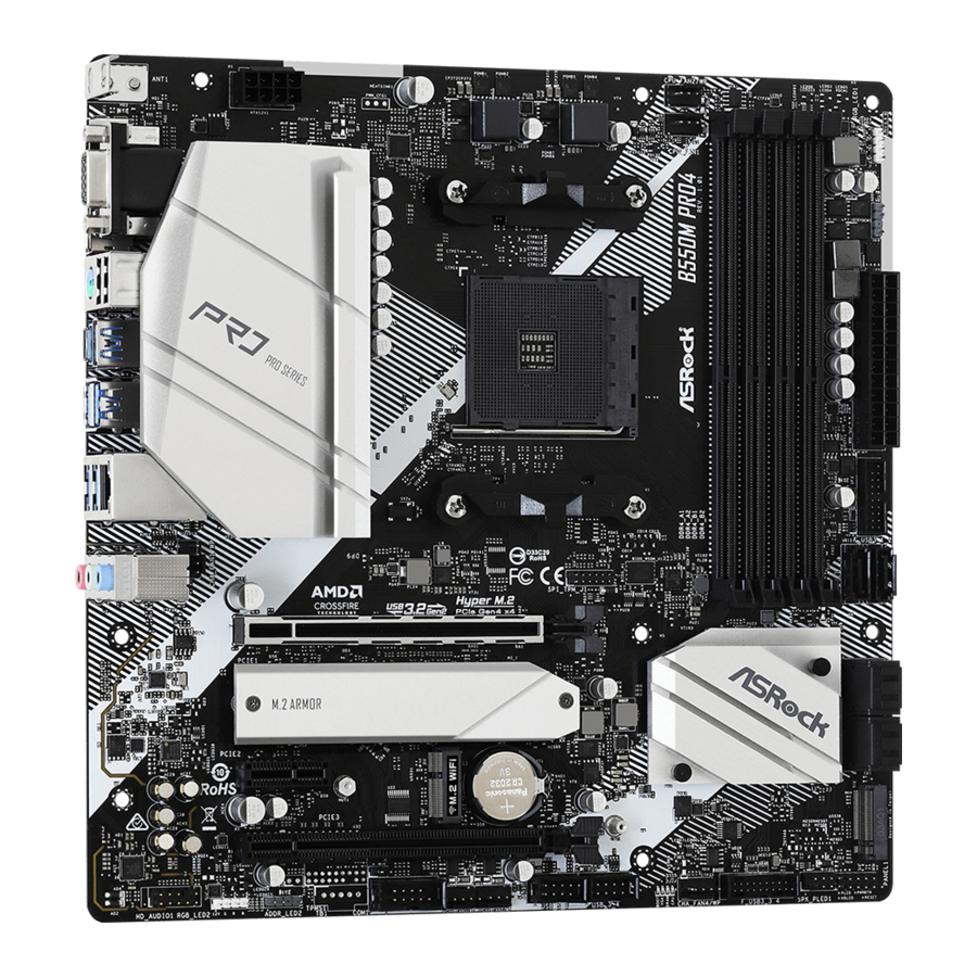
Motherboard Layout

| No. | Description |
| 1 | 8 pin 12V Power Connector (ATX12V1) |
| 2 | CPU Fan Connector (CPU_FAN1) |
| 3 | CPU/Water Pump Fan Connector (CPU_FAN2/WP) |
| 4 | 2 x 288-pin DDR4 DIMM Slots (DDR4_A1, DDR4_B1) |
| 5 | 2 x 288-pin DDR4 DIMM Slots (DDR4_A2, DDR4_B2) |
| 6 | RGB LED Header (RGB_LED1) |
| 7 | Addressable LED Header (ADDR_LED1) |
| 8 | ATX Power Connector (ATXPWR1) |
| 9 | USB 3.2 Gen1 Header (F_USB3_1_2) |
| 10 | SATA3 Connector (SATA3_2) |
| 11 | SATA3 Connector (SATA3_1) |
| 12 | SATA3 Connector (SATA3_4) |
| 13 | SATA3 Connector (SATA3_3) |
| 14 | SATA3 Connector (SATA3_5) |
| 15 | SATA3 Connector (SATA3_6) |
| 16 | System Panel Header (PANEL1) |
| 17 | Power LED and Speaker Header (SPK_PLED1) |
| 18 | USB 3.2 Gen1 Header (F_USB3_3_4) |
| 19 | Chassis/Water Pump Fan Connector (CHA_FAN4/WP) |
| 20 | Post Status Checker (PSC) |
| 21 | SPI TPM Header (SPI_TPM_J1) |
| 22 | USB 2.0 Header (USB_3_4) |
| 23 | USB 2.0 Header (USB_5_6) |
| 24 | Chassis/Water Pump Fan Connector (CHA_FAN2/WP) |
| 25 | Chassis/Water Pump Fan Connector (CHA_FAN3/WP) |
| 26 | Clear CMOS Jumper (CLRCMOS1) |
| 27 | COM Port Header (COM1) |
| 28 | Addressable LED Header (ADDR_LED2) |
| 29 | RGB LED Header (RGB_LED2) |
| 30 | Front Panel Audio Header (HD_AUDIO1) |
| 31 | Chassis/Water Pump Fan Connector (CHA_FAN1/WP) |
I/O Panel

| No. | Description | No. | Description |
| 1 | D-Sub Port | 9 | USB 3.2 Gen2 Type-A Port (USB31_TA_1) |
| 2 | USB 2.0 Ports (USB_12)* | ||
| 3 | LAN RJ-45 Port** | 10 | USB 3.2 Gen2 Type-C Port (USB31_TC_1) |
| 4 | Line In (Light Blue)*** | ||
| 5 | Front Speaker (Lime)*** | 11 | PS/2 Mouse/Keyboard Port |
| 6 | Microphone (Pink)*** | 12 | DisplayPort 1.4 |
| 7 | USB 3.2 Gen1 Ports (USB3_34) | 13 | HDMI Port |
| 8 | USB 3.2 Gen1 Ports (USB3_12) | 14 | Antenna Bracket |
* Please note that the USB_2 consumes auxiliary power (+5VSB) while the other USB ports consume DUAL Power (+5VDUAL). The USB_2 is optimal for connecting the USB Type speaker and headset.
** There are two LEDs on each LAN port. Please refer to the table below for the LAN port LED indications.
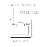
| Activity / Link LED | Speed LED | ||
| Status | Description | Status | Description |
| Off | No Link | Off | 10Mbps connection |
| Blinking | Data Activity | Orange | 100Mbps connection |
| On | Link | Green | 1Gbps connection |
*** Function of the Audio Ports in 7.1-channel Configuration:
| Port | Function |
| Light Blue (Rear panel) | Rear Speaker Out |
| Lime (Rear panel) | Front Speaker Out |
| Pink (Rear panel) | Central /Subwoofer Speaker Out |
| Lime (Front panel) | Side Speaker Out |
Introduction
It delivers excellent performance with robust design conforming to ASRock's commitment to quality and endurance.
 Because the motherboard specifications and the BIOS software might be updated, the content of this documentation will be subject to change without notice. In case any modifications of this documentation occur, the updated version will be available on ASRock's website without further notice. If you require technical support related to this motherboard, please visit our website for specific information about the model you are using. You may find the latest VGA cards and CPU support list on ASRock's website as well. ASRock website http://www.asrock.com.
Package Contents
- ASRock B550M Pro4 Motherboard (Micro ATX Form Factor)
- ASRock B550M Pro4 Quick Installation Guide
- ASRock B550M Pro4 Support CD
- 1 x I/O Panel Shield
- 2 x Serial ATA (SATA) Data Cables (Optional)
- 2 x Screws for M.2 Socket (Optional)
Specifications
| Platform |
|
| CPU |
|
| Chipset |
|
| Memory |
|
| Expansion Slot | AMD Ryzen series CPUs (Matisse)
|
| Graphics |
|
| Audio |
|
| LAN |
|
| Rear Panel I/O |
|
| Storage |
|
| Connector |
|
| BIOS Feature |
|
| Hardware Monitor |
|
| OS |
|
| Certifications |
|
* For detailed product information, please visit our website: http://www.asrock.com
 Please realize that there is a certain risk involved with overclocking, including adjusting the setting in the BIOS, applying Untied Overclocking Technology, or using third-party overclocking tools. Overclocking may affect your system's stability, or even cause damage to the components and devices of your system. It should be done at your own risk and expense.
We are not responsible for possible damage caused by overclocking.
Installation
This is a Micro ATX form factor motherboard. Before you install the motherboard, study the configuration of your chassis to ensure that the motherboard fits into it.
Pre-installation Precautions
Take note of the following precautions before you install motherboard components or change any motherboard settings.
- Make sure to unplug the power cord before installing or removing the motherboard. Failure to do so may cause physical injuries to you and damages to motherboard components.
- In order to avoid damage from static electricity to the motherboard's components, NEVER place your motherboard directly on a carpet. Also remember to use a grounded wrist strap or touch a safety grounded object before you handle the components.
- Hold components by the edges and do not touch the ICs.
- Whenever you uninstall any components, place them on a grounded anti-static pad or in the bag that comes with the components.
- When placing screws to secure the motherboard to the chassis, please do not overtighten the screws! Doing so may damage the motherboard.
Installing the CPU
Unplug all power cables before installing the CPU.


Installing the CPU Fan and Heatsink
After you install the CPU into this motherboard, it is necessary to install a larger heatsink and cooling fan to dissipate heat. You also need to spray thermal grease between the CPU and the heatsink to improve heat dissipation. Make sure that the CPU and the heatsink are securely fastened and in good contact with each other.
Please turn off the power or remove the power cord before changing a CPU or heatsink.
Installing the CPU Box Cooler SR1


Installing the AM4 Box Cooler SR2


*The diagrams shown here are for reference only. The headers might be in a different position on your motherboard.
Installing the AM4 Box Cooler SR3


*The diagrams shown here are for reference only. The headers might be in a different position on your motherboard.
Installing Memory Modules (DIMM)
This motherboard provides four 288-pin DDR4 (Double Data Rate 4) DIMM slots, and supports Dual Channel Memory Technology.
- For dual channel configuration, you always need to install identical (the same brand, speed, size and chip-type) DDR4 DIMM pairs.
- It is unable to activate Dual Channel Memory Technology with only one or three memory module installed.
- It is not allowed to install a DDR, DDR2 or DDR3 memory module into a DDR4 slot; otherwise, this motherboard and DIMM may be damaged.
- We suggest that you install the memory modules on DDR4_A2 and DDR4_B2 first for better DRAM compatibility on 2 DIMMs configuration.
AMD non-XMP Memory Frequency Support
Ryzen Series CPUs (Matisse):
| UDIMM Memory Slot | Frequency | |||
| A1 | A2 | B1 | B2 | (Mhz) |
| - | SR | - | - | 3200 |
| - | DR | - | - | 3200 |
| - | SR | - | SR | 3200 |
| - | DR | - | DR | 3200 |
| SR | SR | SR | SR | 2933 |
| SR/DR | DR | SR/DR | DR | 2667 |
| SR/DR | SR/DR | SR/DR | SR/DR | 2667 |
Ryzen Series APUs (Renoir):
| UDIMM Memory Slot | Frequency | |||
| A1 | A2 | B1 | B2 | (Mhz) |
| - | SR | - | - | 3200 |
| - | DR | - | - | 3200 |
| - | SR | - | SR | 3200 |
| - | DR | - | DR | 3200 |
| SR | SR | SR | SR | 2933 |
| SR/DR | DR | SR/DR | DR | 2667 |
| SR/DR | SR/DR | SR/DR | SR/DR | 2667 |
SR: Single rank DIMM, 1Rx4 or 1Rx8 on DIMM module label
DR: Dual rank DIMM, 2Rx4 or 2Rx8 on DIMM module label
The DIMM only fits in one correct orientation. It will cause permanent damage to the motherboard and the DIMM if you force the DIMM into the slot at incorrect orientation.
")
Expansion Slots (PCI Express Slots)
There are 3 PCI Express slots on the motherboard.
Before installing an expansion card, please make sure that the power supply is switched off or the power cord is unplugged. Please read the documentation of the expansion card and make necessary hardware settings for the card before you start the installation.
PCIe slots:
PCIE1 (PCIe 4.0 x16 slot) is used for PCI Express x16 lane width graphics cards.
PCIE2 (PCIe 3.0 x1 slot) is used for PCI Express x1 lane width cards.
PCIE3 (PCIe 3.0 x16 slot) is used for PCI Express x4 lane width graphics cards.
PCIe Slot Configurations
| PCIE1 | PCIE2 | PCIE3 | |
| Ryzen Series CPUs (Matisse) | Gen4x16 | Gen3x1 | Gen3x4 |
| Ryzen Series CPUs (Renoir) | Gen3x16 | Gen3x1 | Gen3x4 |
For a better thermal environment, please connect a chassis fan to the motherboard's chassis fan connector (CHA_FAN1/WP, CHA_FAN2/WP, CHA_FAN3/WP or CHA_ FAN4/WP ) when using multiple graphics cards.
Jumpers Setup
The illustration shows how jumpers are setup. When the jumper cap is placed on the pins, the jumper is "Short". If no jumper cap is placed on the pins, the jumper is "Open".
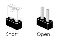
| Clear CMOS Jumper (CLRCMOS1) |  2-pin Jumper | Short: Clear CMOS Open: Default |
CLRCMOS1 allows you to clear the data in CMOS. The data in CMOS includes system setup information such as system password, date, time, and system setup parameters. To clear and reset the system parameters to default setup, please turn off the computer and unplug the power cord, then use a jumper cap to short the pins on CLRCMOS1 for 3 seconds. Please remember to remove the jumper cap after clearing the CMOS. If you need to clear the CMOS when you just finish updating the BIOS, you must boot up the system first, and then shut it down before you do the clear-CMOS action.
Onboard Headers and Connectors
Onboard headers and connectors are NOT jumpers. Do NOT place jumper caps over these headers and connectors. Placing jumper caps over the headers and connectors will cause permanent damage to the motherboard.
System Panel Header (9-pin PANEL1)
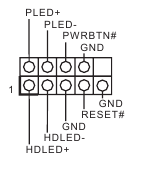
Connect the power button, reset button and system status indicator on the chassis to this header according to the pin assignments below. Note the positive and negative pins before connecting the cables.
PWRBTN (Power Button):
Connect to the power button on the chassis front panel. You may configure the way to turn off your system using the power button.
RESET (Reset Button):
Connect to the reset button on the chassis front panel. Press the reset button to restart the computer if the computer freezes and fails to perform a normal restart.
PLED (System Power LED):
Connect to the power status indicator on the chassis front panel. The LED is on when the system is operating. The LED keeps blinking when the system is in S1/S3 sleep state. The LED is off when the system is in S4 sleep state or powered off (S5).
HDLED (Hard Drive Activity LED):
Connect to the hard drive activity LED on the chassis front panel. The LED is on when the hard drive is reading or writing data.
The front panel design may differ by chassis. A front panel module mainly consists of power button, reset button, power LED, hard drive activity LED, speaker and etc. When connecting your chassis front panel module to this header, make sure the wire assignments and the pin assignments are matched correctly.
| Power LED and Speaker Header (7-pin SPK_PLED1) (see No. 17) |  | Please connect the chassis power LED and the chassis speaker to this header. |
| Serial ATA3 Connectors (SATA3_1: see No. 11) (SATA3_2: see No. 10) (SATA3_3: see No. 13) (SATA3_4: see No. 12) (SATA3_5: see No. 14) (SATA3_6: see No. 15) |  | These six SATA3 connectors support SATA data cables for internal storage devices with up to 6.0 Gb/s data transfer rate. * M2_2 and SATA3_5_6 share lanes. If either one of them is in use, the other one will be disabled. |
| USB 2.0 Headers (9-pin USB_3_4) (see No. 22) (9-pin USB_5_6) (see No. 23) |  | There are two headers on this motherboard. Each USB 2.0 header can support two ports. |
| USB 3.2 Gen1 Headers (19-pin F_USB3_1_2) (see No. 9) |  | There are two headers on this motherboard. Each USB 3.2 Gen1 header can support two ports. |
| (19-pin F_USB3_3_4) (see No. 18) |  | |
| Front Panel Audio Header (9-pin HD_AUDIO1) (see No. 30) |  | This header is for connecting audio devices to the front audio panel. |
- High Definition Audio supports Jack Sensing, but the panel wire on the chassis must support HDA to function correctly. Please follow the instructions in our manual and chassis manual to install your system.
- If you use an AC'97 audio panel, please install it to the front panel audio header by the steps below:
- Connect Mic_IN (MIC) to MIC2_L.
- Connect Audio_R (RIN) to OUT2_R and Audio_L (LIN) to OUT2_L.
- Connect Ground (GND) to Ground (GND).
- MIC_RET and OUT_RET are for the HD audio panel only. You don't need to connect them for the AC'97 audio panel.
- To activate the front mic, go to the "FrontMic" Tab in the Realtek Control panel and adjust "Recording Volume".
| Chassis Water Pump Fan Connectors (4-pin CHA_FAN1/WP) (see No. 31) |  | This motherboard provides four 4-Pin water cooling chassis fan connectors. If you plan to connect a 3-Pin chassis water cooler fan, please connect it to Pin 1-3. |
| (4-pin CHA_FAN2/WP) (see No. 24) (4-pin CHA_FAN3/WP) (see No. 25) (4-pin CHA_FAN4/WP) (see No. 19) |  | |
| CPU Fan Connector (4-pin CPU_FAN1) (see No. 2) |  | This motherboard provides a 4-Pin CPU fan (Quiet Fan) connector. If you plan to connect a 3-Pin CPU fan, please connect it to Pin 1-3. |
| CPU Water Pump Fan Connector (4-pin CPU_FAN2/WP) (see No. 3) |  | This motherboard provides a 4-Pin water cooling CPU fan connector. If you plan to connect a 3-Pin CPU water cooler fan, please connect it to Pin 1-3. |
| ATX Power Connector (24-pin ATXPWR1) (see No. 8) |  | This motherboard provides a 24-pin ATX power connector. To use a 20-pin ATX power supply, please plug it along Pin 1 and Pin 13. |
| ATX 12V Power Connector (8-pin ATX12V1) (see No. 1) |  | This motherboard provides an 8-pin ATX 12V power connector. To use a 4-pin ATX power supply, please plug it along Pin 1 and Pin 5. *  Please make sure that the power cable connected is for the CPU and not the graphics card. Do not plug the PCIe power cable to this connector. |
| Serial Port Header (9-pin COM1) (see No. 27) |  | This COM1 header supports a serial port module. |
| SPI TPM Header (13-pin SPI_TPM_J1) (see No. 21) |  | This connector supports SPI Trusted Platform Module (TPM) system, which can securely store keys, digital certificates, passwords, and data. A TPM system also helps enhance network security, protects digital identities, and ensures platform integrity. |
| RGB LED Headers (4-pin RGB_LED1) (see p.1, No. 6) (4-pin RGB_LED2) (see p.1, No. 29) |  | These two RGB headers are used to connect RGB LED extension cable which allows users to choose from various LED lighting effects. Never install the RGB LED cable in the wrong orientation; otherwise, the cable may be damaged. *Please refer to further instructions on these two headers. |
| Addressable LED Headers (3-pin ADDR_LED1) (see No. 7) (3-pin ADDR_LED2) (see No. 28) |  | These two Addressable headers are used to connect Addressable LED extension cable which allows users to choose from various LED lighting effects. Never install the Addressable LED cable in the wrong orientation; otherwise, the cable may be damaged. *Please refer to for further instructions on this header. |
Post Status Checker
Post Status Checker (PSC) diagnoses the computer when users power on the machine. It emits a red light to indicate whether the CPU, memory, VGA or storage is dysfunctional. The lights go off if the four mentioned above are functioning normally.
M.2 WiFi/BT Module Installation Guide (M2_3)
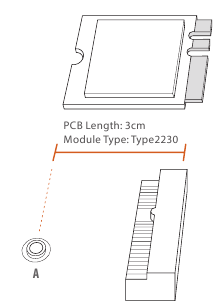
The M.2, also known as the Next Generation Form Factor (NGFF), is a small size and versatile card edge connector that aims to replace mPCIe and mSATA. The M.2 Socket (Key E) supports type 2230 WiFi/BT module.
* The M.2 socket does not support SATA M.2 SSDs.
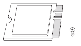
Installing the WiFi/BT module
- Prepare a type 2230 WiFi/BT module and the screw.
![]()
- Find the nut location to be used.
![]()
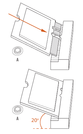
- Gently insert the WiFi/BT module into the M.2 slot. Please be aware that the module only fits in one orientation.
![]()
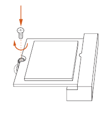
- Tighten the screw with a screwdriver to secure the module into place. Please do not overtighten the screw as this might damage the module.
![]()
M.2_SSD (NGFF) Module Installation Guide (M2_1)
The M.2, also known as the Next Generation Form Factor (NGFF), is a small size and versatile card edge connector that aims to replace mPCIe and mSATA.
The Hyper M.2 Socket (M2_1) supports M Key type 2280 M.2 PCI Express module up to Gen4x4 (64 Gb/s) (with Matisse) or Gen3x4 (32 Gb/s) (with Renoir).
Installing the M.2_SSD (NGFF) Module
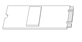
- Prepare a M.2_SSD (NGFF) module and the screw.
![]()
- Depending on the PCB type and length of your M.2_SSD (NGFF) module, find the corresponding nut location to be used.
![]()
No. 1 Nut Location A PCB Length 8cm Module Type Type2280

- Before installing a M.2 (NGFF) SSD module, please loosen the screws to remove the M.2 heatsink. *Please remove the protective films on the bottom side of the M.2 heatsink before you install a M.2 SSD module.
 Module - Step 3")
- Align and gently insert the M.2 (NGFF) SSD module into the M.2 slot. Please be aware that the M.2 (NGFF) SSD module only fits in one orientation.
 Module - Step 4")
- Tighten the screw with a screwdriver to secure the module into place. Please do not overtighten the screw as this might damage the module.
 Module - Step 5")
 Module - Step 3")
 Module - Step 4")
 Module - Step 5")
M.2_SSD (NGFF) Module Support List (M2_1)
 Module Support List (M2_1) Table")
For the latest updates of M.2_SSD (NFGG) module support list, please visit our website for details: http://www.asrock.com
M.2_SSD (NGFF) Module Installation Guide (M2_2)
The M.2, also known as the Next Generation Form Factor (NGFF), is a small size and versatile card edge connector that aims to replace mPCIe and mSATA. The M.2 Socket (M2_2) supports M Key type 2280 M.2 SATA3 6.0 Gb/s module and M.2 PCI Express module up to Gen3 x2 (16 Gb/s).
* M2_2 and SATA3_5_6 share lanes. If either one of them is in use, the other one will be disabled.
Installing the M.2_SSD (NGFF) Module
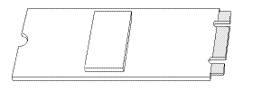
- Prepare a M.2_SSD (NGFF) module and the screw.
![]()
- Depending on the PCB type and length of your M.2_SSD (NGFF) module, find the corresponding nut location to be used.
 Module - Step 1")
No. 1 Nut Location A PCB Length 8cm Module Type Type2280 -
Align and gently insert the M.2 (NGFF) SSD module into the M.2 slot. Please be aware that the M.2 (NGFF) SSD module only fits in one orientation.
 Module - Step 2")
-
Tighten the screw with a screwdriver to secure the module into place. Please do not overtighten the screw as this might damage the module.
 Module - Step 3")
 Module - Step 1")
 Module - Step 2")
 Module - Step 3")
M.2_SSD (NGFF) Module Support List (M2_2)
| Vendor | Interface | P/N |
| ADATA | SATA3 | AXNS330E-32GM-B |
| ADATA | SATA3 | AXNS381E-128GM-B |
| ADATA | SATA3 | AXNS381E-256GM-B |
| ADATA | SATA3 | ASU800NS38-256GT-C |
| ADATA | SATA3 | ASU800NS38-512GT-C |
| Crucial | SATA3 | CT120M500SSD4 |
| Crucial | SATA3 | CT240M500SSD4 |
| Intel | SATA3 | Intel SSDSCKGW080A401/80G |
| Kingston | SATA3 | SM2280S3 |
| Plextor | PCIe | PX-G256M6e |
| Plextor | PCIe | PX-G512M6e |
| Samsung | PCIe x4 | XP941-512G (MZHPU512HCGL) |
| SanDisk | PCIe | SD6PP4M-128G |
| SanDisk | PCIe | SD6PP4M-256G |
| Team | SATA3 | TM4PS4128GMC105 |
| Team | SATA3 | TM4PS4256GMC105 |
| Team | SATA3 | TM8PS4128GMC105 |
| Team | SATA3 | TM8PS4256GMC105 |
| Transcend | SATA3 | TS256GMTS400 |
| Transcend | SATA3 | TS512GMTS600 |
| Transcend | SATA3 | TS512GMTS800 |
| V-Color | SATA3 | VLM100-120G-2280B-RD |
| V-Color | SATA3 | VLM100-240G-2280RGB |
| V-Color | SATA3 | VSM100-240G-2280 |
| V-Color | SATA3 | VLM100-240G-2280B-RD |
| WD | SATA3 | WDS100T1B0B-00AS40 |
| WD | SATA3 | WDS240G1G0B-00RC30 |
For the latest updates of M.2_SSD (NFGG) module support list, please visit our website for details: http://www.asrock.com
ASRock Polychrome SYNC
ASRock Polychrome SYNC is a lighting control utility specifically designed for unique individuals with sophisticated tastes to build their own stylish colorful lighting system. Simply by connecting the LED strip, you can customize various lighting schemes and patterns, including Static, Breathing, Strobe, Cycling, Music, Wave and more.
Connecting the LED Strip
Connect your RGB LED strips to the RGB LED Headers (RGB_LED1, RGB_LED2) on the motherboard.

- Never install the RGB LED cable in the wrong orientation; otherwise, the cable may be damaged.
- Before installing or removing your RGB LED cable, please power off your system and unplug the power cord from the power supply. Failure to do so may cause damages to motherboard components.
- Please note that the RGB LED strips do not come with the package.
- The RGB LED header supports standard 5050 RGB LED strip (12V/G/R/B), with a maximum power rating of 3A (12V) and length within 2 meters.
Connecting the Addressable RGB LED Strip
Connect your Addressable RGB LED strips to the Addressable LED Headers (ADDR_LED1, ADDR_LED2) on the motherboard.

- Never install the RGB LED cable in the wrong orientation; otherwise, the cable may be damaged.
- Before installing or removing your RGB LED cable, please power off your system and unplug the power cord from the power supply. Failure to do so may cause damages to motherboard components.
- Please note that the RGB LED strips do not come with the package.
- The RGB LED header supports WS2812B addressable RGB LED strip (5V/Data/ GND), with a maximum power rating of 3A (5V) and length within 2 meters.
ASRock Polychrome SYNC Utility
Now you can adjust the RGB LED color through the ASRock Polychrome SYNC Utility. Download this utility from the ASRock Live Update & APP Shop and start coloring your PC style your way!

Documents / Resources
References
Download manual
Here you can download full pdf version of manual, it may contain additional safety instructions, warranty information, FCC rules, etc.
Advertisement


Need help?
Do you have a question about the B550M Pro4 and is the answer not in the manual?
Questions and answers