Advertisement
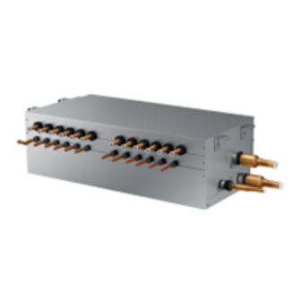
MSB (Mode Selection Box)
Installation manual
V1MSBB01HR / V1MSBB02HR / V1MSBB04HR /
V1MSBB06HR / V1MSBB08HR / V1MSBB12HR
• Thank you for purchasing this Lennox Product.
• Before operating this unit, please read this manual carefully and retain it for future reference.
DB68-13125A-00_IM_Mode Selection Box_AA_EN.indd 1
DB68-13125A-00_IM_Mode Selection Box_AA_EN.indd 1
2024-07-11 오후 4:09:52
2024-07-11 오후 4:09:52
Advertisement
Table of Contents

Related Manuals for Lennox V1MSBB01HR


Summary of Contents for Lennox V1MSBB01HR
- Page 1 Installation manual V1MSBB01HR / V1MSBB02HR / V1MSBB04HR / V1MSBB06HR / V1MSBB08HR / V1MSBB12HR • Thank you for purchasing this Lennox Product. • Before operating this unit, please read this manual carefully and retain it for future reference. DB68-13125A-00_IM_Mode Selection Box_AA_EN.indd 1 DB68-13125A-00_IM_Mode Selection Box_AA_EN.indd 1...
-
Page 2: Table Of Contents
Contents Contents Safety precautions ............................................3 Preparing the installation ..........................................5 Space requirements ............................................8 Refrigerant piping ............................................15 Wiring ................................................18 MSB (Mode Selection Box) Installation Checklist ................................29 2 English DB68-13125A-00_IM_Mode Selection Box_AA_EN.indd 2 DB68-13125A-00_IM_Mode Selection Box_AA_EN.indd 2 2024-07-11 오후 4:09:52 2024-07-11 오후 4:09:52... -
Page 3: Safety Precautions
Safety precautions California Proposition 65 Warning (US) WARNING: Cancer and Reproductive Harm - www.P65Warnings.ca.gov. The safety information and precautions below must be kept for the safety of users and installers. Before installing an VRF, please read this manual thoroughly to ensure that you know how to safely and efficiently install a new appliance. - Page 4 Safety precautions Contents When turning on the power, make sure to connect the power supply to the circuit breaker designated for indoor units. (ELCB, ELB, MCCB) X If you do not install the circuit breaker for MSB(ELCB, ELB, MCCB), excessive current or failure to blocking the power supply may cause electric shock, a fire.
-
Page 5: Preparing The Installation
Pattern Name Cable tie V1MSBB02HR V1MSBB06HR (for pipe) (for base) manual sheet V1MSBB01HR V1MSBB08HR V1MSBB12HR Shape Soundproof and soundproofing materials Name V1MSBP01HR Shape Selecting the refrigerant pipe for installation The design pressure of MSB for R-410A is about 4.1 MPa (594.6psi). For safe use of the product, please refer to the table below in selecting the installation pipe. - Page 6 Before installing MSB, refer to the compatible table below and find the model before installation. Outdoor unit Indoor unit V1MSBB06HR V1MSBB04HR V1MSBB02HR VRF Outdoor VRF Indoor V1MSBB01HR V1MSBB12HR V1MSBB08HR Model Description V1MSBB06HR below 61.6 kW (216MBH) V1MSBB04HR below 61.6 kW (216MBH)
- Page 7 Liquid pipe connected to indoor unit Gas pipe connected to indoor unit ø 9.52 (ø 3/8) WELDING ø 15.88 (ø 5/8) WELDING <V1MSBB01HR> Liquid pipe connected to indoor unit Gas pipe connected to indoor unit ø 9.52 (ø 3/8) WELDING ø...
- Page 8 Space requirements Space requirements Space requirements Contents 1. Refrigerant noise can be generated during MSB operation. Do not install the unit in spaces that require silence, such as bedrooms, libraries, hospitals, offices etc. 2. Do not install the MSB in the ceiling of living spaces. Noise generated from the MSB may disrupt occupant comfort. <Spaces with open ceiling>...
- Page 9 Refrigerant pipe less V1MSBB04HR V1MSBB02HR Do not install the MSB to close to the ceiling textile[minimum 50mm(2")] V1MSBB01HR V1MSBB12HR Ceiling textile V1MSBB08HR 9. Select an installation location with enough space for service and repair. Leave enough space between adjacent walls and structures. Refer to the examples below.
-
Page 10: Space Requirements
Not included Internal EEV Cannot connect indoor unit without internal EEV Model V1MSBB04HR V1MSBB02HR V1MSBB01HR Exterior of MSB Number of connectable indoor units at one port Up to 8 units Up to 8 units Up to 8 units Maximum number of indoor units (Total) - Page 11 MSB which are connected in series. Example: V1MSBB12HR + V1MSBB06HR → 85.0 kW (290MBH) [V1MSBB06HR, V1MSBB04HR, V1MSBB02HR, V1MSBB01HR] When twinning 2 adjacent ports, Y-connectors can only be connected to the port combinations noted below. Allowed Y-connector port combinations: A + B, C + D, E + F ports...
- Page 12 Space requirements [V1MSBB12HR, V1MSBB08HR] When twinning 2 adjacent ports, Y-connectors can only be connected to the port combinations noted below.: [#1-A] + [#1-B] port, [#1-C] + [#1-D] port, [#1-E] + [#1-F] port [#2-A] + [#2-B] port, [#2-C] + [#2-D] port, [#2-E] + [#2-F] port Y-connector port combinations that are NOT allowed: #1 Ports: B + C port, D + E port, any non-continuous port (example: A+C) #2 Ports: B + C port, D + E port, any non-continuous port (example: A+C) Set Dip Switch Settings when using Y-connector...
- Page 13 *Length (Between the locations of suspension bolts) *Length V1MSBB06HR Anti vibration V1MSBB04HR 764(30.08) rubber Washer V1MSBB02HR V1MSBB01HR 374(14.74) V1MSBB12HR Fasten the nut firmly 1016(40.00) V1MSBB08HR <Location and intervals of fixed suspension bolts> <Fixing the bolt> English DB68-13125A-00_IM_Mode Selection Box_AA_EN.indd 13 DB68-13125A-00_IM_Mode Selection Box_AA_EN.indd 13...
- Page 14 Space requirements Contents 5. How to connect the pipe line. Protect with wet towel when welding 70 mm Pipe connection from outdoor unit ← Default installing direction. Low pressure gas pipe conection (welding) High pressure gas pipe connection (welding) Liquid pipe connection (welding) Pipe connection to indoor unit Liquid pipe (welding) Gas pipe (welding)
-
Page 15: Refrigerant Piping
Refrigerant piping Pipe brazing instructions and cautions Keeping refrigerant pipe clean and dry X To prevent foreign materials or water from entering the pipe, it is important to keep the refrigerant pipe clean, dry and sealed during installation. Exposure place Exposure time Sealing type Longer than one month... - Page 16 Refrigerant piping Pipe insulating instructions and cautions Make sure to check for gas leakage before completing the installation (hose and pipe insulation) and insulate hoses and pipes when there is no sign of leakage. 1. To avoid condensation problems, place T13.0 (1/2") or thicker Acrylonitrile No gap Butadien Rubber separately around each refrigerant pipe.
- Page 17 Refrigerant pipe before EEV kit and MSB or without EEV kit and MSB Insulation Insulation X You can contact the gas side and liquid side pipes but the pipes should not be pressed. X When contacting the gas side and gas side pipe, use 1 grade thicker insulator. Liquid pipe Gas pipe Refrigerant pipe after EEV kit and MSB...
-
Page 18: Wiring
Wiring Installing the circuit breaker and wires Power supply MCCB Power cable Earth cable Communication cable Max : 242V x [A], 30mmA 0.0039inch 0.0039inch x [A] 0.0012~0.0023inch (0.75~1.5mm (2.5mm (2.5mm Min : 198V 0.1 sec x [A] ≥ 1.25 X 1.1 X ∑Ai (x [A] : MCCB/ELB ampheres, ∑Ai : Sum of the rated current ampheres of indoors) Installing the wire X Supply the 208-230V power to L1, L2 (L, N) of MSB separately... - Page 19 X Power line and communication line must be installed as shown in drawing Hole size is Φ 43.7 mm (1.72 inches) Hole for MSB main Hole for MSB main Hole for MSB main power supply power supply power supply Hole for communication Hole for communication Hole for communication...
- Page 20 Wiring Contents Setting MSB address and port When counting the quantity of MSBs while outdoor unit installation, one MSB is one. However, in the case of V1MSBB12HR and V1MSBB08HR, one MSB must be counted as two MSBs. Process 1. MSB address Set MSB address by rotary switch.
- Page 21 Default 2 3 4 Using A, B, C, F port 3. DIP switch [V1MSBB06HR, V1MSBB04HR, V1MSBB02HR, V1MSBB01HR] setting When twinning 2 adjacent ports, Y-connectors can only be connected to the port combinations noted below. for using Allowed Y-connector port combinations: A + B, C + D, E + F ports...
- Page 22 Wiring Contents Process 3. DIP switch [V1MSBB12HR, V1MSBB08HR] setting When twinning 2 adjacent ports, Y-connectors can only be connected to the port combinations noted below.: for using [#1-A] + [#1-B] port, [#1-C] + [#1-D] port, [#1-E] + [#1-F] port Y-connetor [#2-A] + [#2-B] port, [#2-C] + [#2-D] port, [#2-E] + [#2-F] port Y-connector port combinations that are NOT allowed: #1 Ports: B + C port, D + E port, any non-continuous port (example: A+C)
- Page 23 Process 4. MSB address Auto setting: refer to 'auto pipe pairing' in outdoor installation manual. and port Manual setting : setting for 1. Wireless remote controller indoor unit 1) Enter mode to set option (for wireless 2) Assign an indoor unit MSB port address by wireless remote controller remote –...
- Page 24 Wiring Process 4. MSB address 2. Wired controller and port – Setting for VSTAT02P-1 setting for 1) Press the top right corner (hidden button) of the display for more than 3 seconds then release it. indoor unit Then you can press [ + ]/[ - ] buttons and select No.3 and press [ OK ] button. (for wired 2) Assign an indoor unit MSB port address with main menu 4, sub menu 7 (MSB address is assingned controller)
- Page 25 Service mode Please enter your PASSWORD 3. Setting by using Lennox Service Software Set the pipe addresses by using Add-on > Change address on Lennox Service Software. (For more information, see the Lennox Service Software Help.) English DB68-13125A-00_IM_Mode Selection Box_AA_EN.indd 25 DB68-13125A-00_IM_Mode Selection Box_AA_EN.indd 25...
- Page 26 Wiring • The Direct-connected indoor unit without MSB like below picture, be sure to set their options to "Cooling only unit setting“ and then connect them to a low pressure gas pipe and a liquid pipe. This indoor unit only operate to cooling mode. NOTE •...
- Page 27 Option SEG7 SEG8 SEG9 SEG10 (When setting SEG3) (When setting SEG3) Compensation option for Long pipe or height Standard for mode Explanation PAGE Time required for changing Cooling → diffference between indoor units mode change Heating mode Indication Details Indication Details Indication Details...
- Page 28 Wiring Contents Display segment Display Contents Remarks (Pushed time) Indoor unit main address for matching with port A Indoor unit main address of port A : 0 Indoor unit main address for matching with port B Indoor unit main address of port B : 3 Indoor unit main address for matching with port C Indoor unit main address of port C : 6 Indoor unit main address for matching with port D...
- Page 29 MSB (Mode Selection Box) Installation Checklist MSB (Mode Selection Box) Installation Checklist Item Check 1. If the gas leaking test has been completed or not. 2. If MSB has been fixed securely enough to avoid the danger of vibration and falling or not. 3.
- Page 30 DB68-13125A-00_IM_Mode Selection Box_AA_EN.indd 30 DB68-13125A-00_IM_Mode Selection Box_AA_EN.indd 30 2024-07-11 오후 4:09:59 2024-07-11 오후 4:09:59...
Need help?
Do you have a question about the V1MSBB01HR and is the answer not in the manual?
Questions and answers