
Subscribe to Our Youtube Channel
Related Manuals for Lennox ALLEGRA II


Summary of Contents for Lennox ALLEGRA II
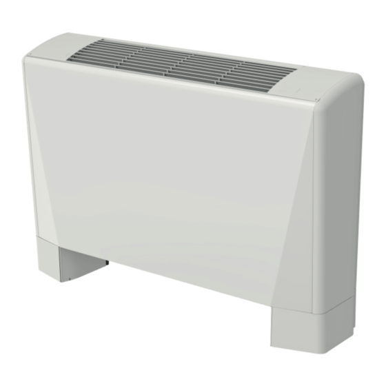
- Page 1 INSTALLATION, USE, MAINTENANCE MANUAL CENTRIFUGAL FAN COIL UNIT ALLEGRA II 0,6 - 6,7 kW 105 - 1500 m3/h ALLEGRA2-IOM-1803-E www.lennoxemea.com...
-
Page 3: Table Of Contents
INSTALLATION, USE, MAINTENANCE MANUAL INDEX INTRODUCTION RECOMMENDATIONS TRANSPORTATION, RECEIVING, HANDLING SAFETY RULES GENERAL DIMENSIONS DIMENSIONAL CHARACTERISTICS MAIN COMPONENTS RECOMMENDATIONS FOR INSTALLATION FAN COIL INSTALLATION WATER CONNECTIONS Connection to the water mains Condensate water drainage ELECTRICAL CONNENCTION CONNECTIONS TO THE TERMINAL BOARD Without control panel With control panel CHANGING THE MOTOR SPEED OF ROTATION... -
Page 4: Introduction
INSTALLATION, USE, MAINTENANCE MANUAL INTRODUCTION TRASPORTATION, RECEIVING, HANDLING This installation, operation and maintenance booklet should always accompany The appliance is dispatched enclosed in special protective packaging, which the fancoil ready consultation by the installer or user if necessary. The appliance should be kept intact until the appliance is positioned in the final place of in- should be installed in compliance with regulations in force in each country and stallation. -
Page 5: General Dimensions
INSTALLATION, USE, MAINTENANCE MANUAL GENERAL DIMENSIONS Pic. 02 * NOTE: the dimensions shown are referred at system with left hydraulic connections DIMENSIONAL CHARACTERISTICS 2 PIPE SYSTEM MOD. Fans number n° Coils numbers n° Rows number n° Coil used for Water content litri cooling and heating... -
Page 6: Main Components
INSTALLATION, USE, MAINTENANCE MANUAL MAIN COMPONENTS Pic. 03 Heat exchanger Electric motor Auxiliary drain pan Water low temperature sensor Centrifugal fan Cabinet Control panel Condense discharge Bearing structure Drain pan Knockouts Terminal board Air filter Valves Supply grills RECOMMENDATIONS FOR INSTALLATION FAN COIL INSTALLATION Before installing the appliance, ensure that: Before installing the appliance, remove the housing (if present). -
Page 7: Water Connections
INSTALLATION, USE, MAINTENANCE MANUAL Il mobile di copertura è rivestito da un film protettivo: toglierlo prima di fissare il mobile alla macchina. Rimontare il mobile di copertura (se previsto), altrimenti l’apparecchio deve essere mascherato a cura del cliente. ATTENZIONE! Proteggere l’apparecchio con un cartone nel caso in cui le opere murarie dell’edificio debbano ancora teminare (Pic. -
Page 8: Condensate Water Drainage
INSTALLATION, USE, MAINTENANCE MANUAL WATER CONNECTIONS CONDENSATE WATER DRAINAGE CONNECTIONS TO THE TERMINAL BOARD The condensate drain pipe should slope downwards by at least 3 cm/m and WITHOUT CONTROL PANEL should not have ascending or throttled section in order to ensure a regular flow The electrical connections should be made to the terminal board on the side of of water. -
Page 9: Changing The Motor Speed Of Rotation
INSTALLATION, USE, MAINTENANCE MANUAL E) Take out auxiliary coil (C), if present, CHANGING THE MOTOR SPEED OF ROTATION and standard coil (B). The fan coil motor has 6 speed settings, 3 of which are connected in the fac- Prestare attenzione a non tagliarsi con tory (red, blue and black wires connected to the motor auto-transformer). -
Page 10: Work Limits
INSTALLATION, USE, MAINTENANCE MANUAL USING THE CONTROL PANEL WORK LIMITS If the appliance has a built-in control panel, raise the flap and proceed as follows. SUMMER (COOLING) Minimum inlet water temperature +4°C Maximum operating pressure 8 bar Maximum room air temperature +35°C Maximum room air humidity Pic. -
Page 11: Cleaning And Maintenance
INSTALLATION, USE, MAINTENANCE MANUAL CLEANING THE HOUSING AND THE CONTROL PANEL CLEANING AND MAINTENANCE To clean the housing, use a dry soft cloth to avoid scratching the enamel. The appliance requires no periodic maintenance. Simple checks by the user to To clean the control panel and the air outlet louvres, use a vacuum cleaner fitted keep it in perfect working order are, however, necessary. - Page 12 INSTALLATION, USE, MAINTENANCE MANUAL DISMANTLING THE APPLIANCE This appliance is made to last for many years. Qualified personnel are needed to dismantle it in all safety. The first operation to be carried out before disman- tling the appliance is to disconnect it totally from the electricity supply. This appliance has been made using recyclable materials (copper, aluminium, brass, plastic) assembled by screws and push-fits to make separation of the parts easy.
- Page 14 +33 4 72 23 20 20 +33 4 72 23 20 20 Due to LENNOX EMEA ongoing commitment to quality, the specifications, ratings and dimensions are subject to change without notice and without incurring liability. Improper installation, adjustment, alteration, service or maintenance can cause property damage or personal injury.
Need help?
Do you have a question about the ALLEGRA II and is the answer not in the manual?
Questions and answers