Advertisement
Introduction
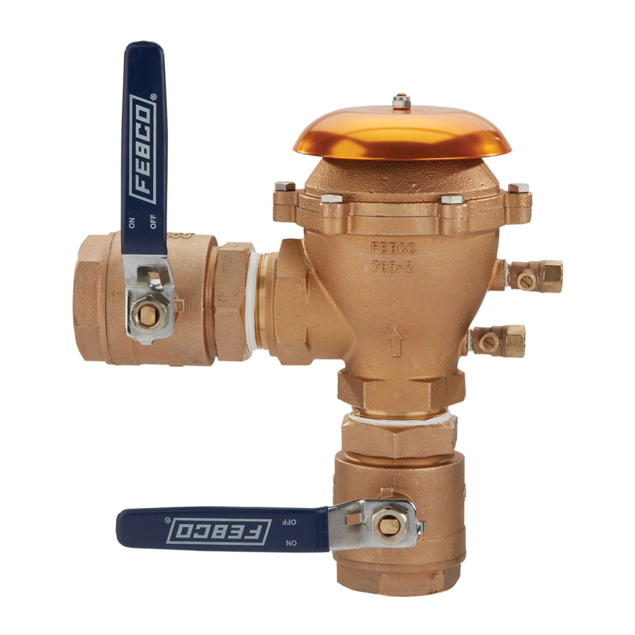
Series 765 Pressure Vacuum Breakers are used to protect against health hazard and non-health hazard backsiphonage conditions in industrial plants, cooling towers laboratories, laundries, swimming pools, and lawn sprinkler systems.
The series includes a sensor for use with SentryPlus Alert technology to monitor temperature and alert facility personnel when freeze conditions can cause damage to equipment. (The sensor is installed on the assembly exterior and does not alter assembly functions or certifications.) The monitoring system is compatible with BMS and irrigation management systems, allowing freeze alerts to be distributed according to the BMS or IMS application. When the monitoring system is Wi-Fi enabled, notifications can be issued through the Smart Freeze Alert cloud service.
NOTICE
An add-on connection kit (sold separately) is required to activate the freeze sensor. Without the connection kit, the sensor is a passive component that has no communication with any other device. (The kit can also be used to install an alternative standalone outdoor sensor or to retrofit existing installations. For ordering details, see "Add-on/Retrofit Sensor Connection Kit.")
NOTICE
Use of the freeze sensor and activation kit with FZ models does not replace the need to comply with all required instructions, codes, and regulations related to installation, operation, and maintenance of the PVB assembly.
Installation Guidelines
- Consult local codes for requirements and restrictions applicable to the area. FEBCO recommends at least 20 psi (138 kPa) for system supply pressure.
- Install the valve only in the orientation/flow direction shown. The air inlet operates in the vertical position. Installation in any other manner causes the device to malfunction.
- Install the valve where it is accessible for periodic testing, maintenance, and repair. The clearances recommended apply to exterior and interior installations. (See Figures 1 and 2.) These minimums do not apply to removable protective enclosures. Refer to local codes for requirements in the area.

- Before installing the valve into the supply line, flush the line of all foreign material.
NOTICE
Failure to flush the line may cause the check valves to become fouled and require disassembly for cleaning. Install the device where spillage is not objectionable, as instantaneous siphon conditions and pressure surges can cause spitting. - When threading the assembly in line, place the wrench only on the ball valve hex ends. Keep pipe dope (sealant) off the interior surfaces of the valve. After installation, fill the assembly with water and test the device to ensure proper operation. Open the inlet ball valve to pressurize the unit. Slowly open the outlet ball valve to fill the downstream line.
NOTICE
Maintain the downstream pressure above 5 psi (34 kPa) to keep the spring-loaded air inlet poppet closed. If the check valve fails to hold 10 psi minimum, it has become fouled and must be cleaned. Close both ball valves and bleed pressure from the device before disassembly. (For more information, see "Service Procedure.")
NOTICE
All assemblies are tested at the factory for proper operation and leakage. If the valve does not pass the field test, it may contain a fouled check valve. This condition is not covered by the factory warranty. Remove the valve cover then inspect and clean the check seats. Any damage or improper operation caused by pipeline debris or improper installation/startup is not included in the factory warranty. In case of a warranty claim, contact the local supplier or FEBCO representative. Do not remove the assembly from the pipeline. - Protect the assembly from freezing and excessive pressure increases. Pressure increases can be caused by thermal expansion or water hammer. Eliminate excessive pressure situations to protect the valve and system from possible damage. Use the plastic test cock plugs and tethers included in the packaging, if required. For information on freeze protection, download IS-F-765-Winterization.

Field Testing Procedure
FEBCO recommends the use of the appropriate test method presented in the ASSE Series 5000 manual that is consistent with the local codes.
Before starting the procedure, remove the freeze sensor mounting clip from the test cock and set it aside to avoid damage. After the procedure is finished, reattach the clip on either test cock.
Equipment Required
Sight Tube Test Kit (1" clear plastic Sight Tube about 40" long with appropriate fittings to attach to test cocks of vacuum breaker)
Purpose of Test
To test the air inlet and the check valves for proper performance.

Test Air Inlet
The air inlet must be tested to verify opening above 1 psi.
(For visual aid information, see Figure 3.)
- Remove the canopy from the top of the vacuum breaker to expose the air inlet.
- Install the sight tube at test cock No. 2.
- Close ball valve B on the discharge side of the vacuum breaker.
- Open test cock No. 2, fill the tube to about 30" above the poppet, then close the test cock.
- Close ball valve A on the inlet side of the vacuum breaker.
- Slowly open test cock No. 2 while watching the poppet in the air inlet. The poppet must unseat. If the air inlet does not open, it is sticking and must be repaired.
- Close test cock No. 2 and remove the sight tube.
Test Check Valve
The check valve must be tested to hold against 1 psi in the direction of flow.
- Install the sight tube at test cock No. 1.
- Open ball valve A to allow the unit to refill with water.
- Open test cock No. 1 and allow the sight tube to fill about 30" above the top of the unit, then close the test cock.
- Close ball valve A. (Ball valve B should already be closed.)
- Open test cock No. 1.
- Open test cock No. 2. Water may run from test cock No. 2 initially, but should stop after a short time. The level of water in the sight tube may drop a little, but should not drop below 28" above the check valve. (Centerline of the discharge ball valve.) If the level in the sight tube continues to drop and water continues to run out of test cock No. 2, the check valve is leaking and must be repaired.
- Close test cocks No. 1 and No. 2.
Restore Operation
Restore all valves and test cocks to the original positions and replace the canopy.
Service Procedure
The general service instructions apply to all sizes. (For visual aid information, see "Parts.")
Before starting the procedure, remove the freeze sensor mounting clip from the test cock and set aside to avoid damage. After the procedure is finished, reattach the clip on either test cock.
- Rinse all parts with clean water before assembly.
- DO NOT USE ANY PIPE DOPE, OIL, GREASE, OR SOLVENT ON ANY PARTS unless instructed to do so.
- Do not force the parts into place. The parts should fit freely together. Excess force may cause damage and render the device inoperable.
- Carefully inspect seals, seating surfaces, and other areas for damage or debris.
- Test the unit after servicing to ensure proper operation.
- Tighten the canopy nut only until it cannot turn freely.
- Rapidly open the inlet ball valve to minimize spillage through the air vent.
- Slowly open the outlet ball valve.
- Test the unit to ensure proper operation.
- Test the unit after servicing to ensure proper operation.
Sizes 1/2 inch to 1 1/4 inch
- Disassemble the bonnet/poppet.
- Close the outlet ball valve then close the inlet ball valve. Bleed the residual pressure by opening test cock No. 2.
- Remove the canopy nut and the canopy.
- Unscrew the bonnet assembly from the valve body by hand. (If necessary, use an appropriate-sized wrench on the outside diameter of the bonnet. However, this may cause damage and require replacement of the bonnet assembly.)
- Remove the poppet/seal assembly from the body.
- Remove the check valve.
- Evenly depress the retaining bracket approximately 1/4", and rotate the bracket 90 degrees.
- Remove the bracket and the spring and check assembly.
- Replace the check valve seal.
- Remove the screw holding the guide, and lift the seal from its holder.

Do not damage the guide legs or the guide pin of the holder.
- Insert the seal disc into the holder, position the guide in the center of the seal, and thread the retaining screw through the guide into the holder.
- Lightly tighten the screw to hold the guide from rotation.
Overtightening may cause distortion of the guide legs.
- Reassemble the device by reversing the preceding steps and using the following special instructions.
- Position the check assembly into the valve body. Position the spring into the recessed area on the top side of the check assembly.
NOTICE
In some cases it may be easier to position the spring on the check assembly before positioning it in the valve body. - When installing the retaining bracket, ensure the spring is centered on the base of the bracket.
- Roll the rubber disc into the recess on the poppet and position the poppet assembly in the valve body.
- To ease assembly of the bonnet into the valve body, apply a thin coating of petroleum jelly on the O-ring. DO NOT USE ANY OTHER LUBRICANT.
- Ensure the guide pin of the bonnet correctly enters the hole in the poppet.
- Thread the bonnet into the valve body by hand until the bonnet flange bottoms on the top surface of the valve body. DO NOT OVERTIGHTEN.
- Tighten the canopy nut only until the canopy cannot turn freely.
- Rapidly open the inlet ball valve to minimize spillage through the air vent, then slowly open the outlet ball valve.
- Position the check assembly into the valve body. Position the spring into the recessed area on the top side of the check assembly.
Sizes 1 1/2 inch to 2 inch
- Disassemble the unit.
- Close the outlet ball valve then close the inlet ball valve. Bleed the residual pressure by opening test cock No. 2.
- Remove the six bonnet bolts, lift the bonnet from the valve body, then remove the poppet and the seat disc.
- To replace poppet spring, unscrew the nut and the guide pin and remove the spring. Use caution to avoid damage to the guide pin. Install a new spring and reassemble.
- Remove the spring retaining the web and the spring and check assembly.
- Replace the valve seal.
- Remove the guide retaining the nut and guide, then lift the seal from the holder.
- Insert a new seal, position the guide in the center of the holder/seal, and thread the nut to retain the guide. Lightly tighten the nut to keep the guide from rotating.
- Reassemble the unit.
- Position the check valve assembly, spring, and retaining web in the valve body. Ensure the arms of the retaining web are aligned with the guide and supports in the valve body.
- Roll the rubber disc into the recess on the poppet and position the poppet assembly in the retaining web. Place the bonnet on the valve body. Ensure the retaining web is properly supported by the three case bosses inside the bonnet.
- Insert the bonnet bolts and tighten.
- Rapidly open the inlet ball valve to minimize spillage in the air vent, then slowly open the outlet ball valve.
- Test the unit to ensure proper operation.
Parts

*Commercial parts
Call customer service if you need assistance with technical details.
| FIGURE NO. | DESCRIPTION | QUANTITY | 1/2" | 3/4" | 1" | 1 1/4" | 1 1/2" | 2" |
| 1 | Nut | 523-533-00 | 523-533-00 | 523-543-00 | 523-543-00 | 523-543-00 | 523-543-00 | |
| 2 | Canopy | 300-092 | 300-093 | 300-089 | 300-089 | 300-083 | 300-083 | |
| 4 | Bolt | 6 | - | - | - | - | 1024564 | 1024564 |
| 6 | O-Ring | 1101068 | 1101068 | 398-140-72 | 398-140-72 | 398-247-72 | 398-247-72 | |
| 7 | Spring | - | - | - | - | 630-096 | 630-096 | |
| 10 | Stem | - | - | - | - | 200-767 | 200-767 | |
| 13 | Retainer | 300-096 | 300-096 | 300-088 | 300-088 | - | - | |
| 14 | Spring | 630-108 | 630-108 | 630-106 | 630-106 | 630-063 | 630-063 | |
| 20 | Test Cock | 2 | 781-074 | 781-074 | 781-075 | 781-075 | 781-075 | 781-075 |
| 22 | Ball Valve | 2 | 781-047 | 781-048 | 781-049 | 781-050 | 781-051 | 781-052 |
| Parts Kit | ||||||||
| Rubber Parts Kit (6, 11, 16) | 905-020 | 905-020 | 905-021 | 905-021 | 905-022 | 905-022 | ||
| Bonnet Assembly (5-10) | 905-047 | 905-047 | 905-048(2) | 905-048(2) | - | - | ||
| Bonnet/Kit (3, 5-10) | - | - | - | - | 901-857 | 901-857 | ||
| Poppet Assembly (11,12) | 905-049 | 905-049 | 905-050 | 905-050 | 901-860 | 901-860 | ||
| Check Assembly (15-18) | 905-051 | 905-051 | 905-052 | 905-052 | - | - | ||
| Check Repair Kit (6, 13, 15-18) | - | - | - | - | 905-070 | 905-070 | ||
| Bonnet/Poppet Kit (5-12) | 905-211 | 905-211 | 905-212(2) | 905-212(2) | - | - | ||
(2) Kit includes parts to retrofit older style units.
Troubleshooting
| PROBLEM | CAUSE | SOLUTION |
Check value fails to hold 1 psid minimum | Debris on sealing surface, guide surfaces, or valve surfaces | Disassemble and clean check |
| Damaged seat disc | Disassemble and replace seal | |
| Weak or broken spring | Disassemble and replace spring | |
| Poppet broken due to thermal expansion | Replace broken poppet (Refer to IS-F-765-Winterization at watts.com.) | |
Poppet fails to open at 1 psig minimum | Debris restricting free operation | Disassemble and clean check valve surfaces |
| Poppet seal adhering to bonnet | Disassemble and clean and/or replace damaged parts | |
| Weak spring load | Replace bonnet assembly (½" to 1¼") Replace spring (1½" and larger) | |
Minor leakage through air vent | Damaged poppet seal | Disassemble and replace seal |
| Cracked or damaged poppet | Disassemble and replace poppet seal | |
| Cracked bonnet or damaged sealing edge | Disassemble and replace bonnet assembly | |
| Debris on sealing surface | Disassemble and clean | |
Significant discharge through air vent | Poppet not properly guided | Disassemble and replace damaged parts |
| Major poppet or seal failure | ||
| Low downstream pressure | Check pressure at test cock No. 2; should be higher than 5 psig if low system | |
| Insufficient inlet volume to operate device | Increase pressure or partially close outlet ball valve to create higher pressure on poppet | |
| Poppet and or bonnet broken due to thermal expansion | Replace broken bonnet/poppet (Refer to IS-F-765-Winterization at watts.com.) | |
Chatter during flow conditions | Worn, damaged, or defective check valve guide | Disassemble and repair or replace guide |
Add-on/Retrofit Sensor Connection Kit
| ORDERING CODE | ADD-ON/RETROFIT KIT | DESCRIPTION |
| 88009516 |  FP-FBF-WiFi/BMS/IMS-FZ Freeze Sensor Connection Kit | Includes freeze sensor in mounting clip, standalone outdoor sensor, activation module, wire nuts (2), and power adapter. This kit adds a monitoring system to alert facility personnel when temperature nears and reaches the freezing point. |
Warnings

Read this Manual BEFORE using this equipment.
Failure to read and follow all safety and use information can result in death, serious personal injury, property damage, or damage to the equipment.
Keep this Manual for future reference.
Local building or plumbing codes may require modifications to the information provided. You are required to consult the local building and plumbing codes prior to installation. If the information provided here is not consistent with local building or plumbing codes, the local codes should be followed. This product must be installed by a licensed contractor in accordance with local codes and ordinances.
Need for Periodic Inspection/Maintenance: This product must be tested periodically in compliance with local codes, but at least once per year or more as service conditions warrant. All products must be retested once maintenance has been performed. Corrosive water conditions and/or unauthorized adjustments or repair could render the product ineffective for the service intended. Regular checking and cleaning of the product's internal and external components helps assure maximum life and proper product function.
Freeze sensor solely provides alerts about a possible freeze event and cannot prevent a freeze event from occurring. User action is required to prevent freeze conditions from causing product and/ or property damage.
USA: T: (800) 767-1234 • FEBCOonline.com
Canada: T: (888) 208-8927 • FEBCOonline.ca
Latin America: T: (52) 55-4122-0138 • FEBCOonline.com
Documents / Resources
References
Download manual
Here you can download full pdf version of manual, it may contain additional safety instructions, warranty information, FCC rules, etc.
Download Watts FEBCO 765 Series, FBT765CBV, FBT765HBV, FBT765EBV, FBT765FBV Manual
Advertisement


Need help?
Do you have a question about the FEBCO 765 Series and is the answer not in the manual?
Questions and answers