Table of Contents
Advertisement
Quick Links
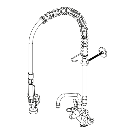
Food Service Pre-Rinse Assemblies
Installation and Maintenance Instructions
FHS001
FHS141
FHS002
FHS141C
FHS011
FWS001
FHS021
FWS011
FHS031
FWS021
FHS041
FWS031
FHS121
FWS031ADJ
FHS131
FWS101
technical data
Working Pressure Range
Maximum Static Pressure
Maximum Working
Temperature
Inlet Connection
Flow Rate
Enware products are to be installed in accordance with the Plumbing Code of Australia (PCA) and AS/NZS3500.
Installations not complying with PCA and AS/NZS 3500 may void the product and performance warranty provisions.
Reference should also be made to the Australasian Health Facility Guidelines (AHFG), ABCB and Local Government
regulations when considering the choice of, and the installation of these products.
This product must be installed and commissioned by a qualified plumber.
For use with potable water only.
NOTE: Enware Australia advises:
1. Due to ongoing Research and Development, specifications may change without notice.
2. Component specifications may change on some export models.
I00063_09 Oct 2023
1300 369 273 | info@enware.com.au | enware.com.au
FWS121
FWS121C
FWS121W
FWS131
FWS131ADJ
FS704
Min 50 kPa
Max 500 kPa
1200 kPa
95°C (Jumper Valve)
85°C (Spring loaded valve / Pre-Rinse spray gun)
1/2" BSP
5/8" BSP (In-wall recessed SBA)
4 L/min (Pre-rinse spray gun)
8 L/min (Pot filler)
With New Leva Handles
Advertisement
Table of Contents

Related Manuals for Watts ENWARE FHS001


Summary of Contents for Watts ENWARE FHS001
- Page 1 Food Service Pre-Rinse Assemblies Installation and Maintenance Instructions FHS001 FHS141 FWS121 FHS002 FHS141C FWS121C FHS011 FWS001 FWS121W FHS021 FWS011 FWS131 FHS031 FWS021 FWS131ADJ FHS041 FWS031 FS704 With New Leva Handles FHS121 FWS031ADJ FHS131 FWS101 technical data Min 50 kPa Working Pressure Range Max 500 kPa Maximum Static Pressure 1200 kPa...
-
Page 2: Installing The Base
assembly and installation procedure • Ensure all supply lines are flushed thoroughly IMPORTANT - Before proceeding with Installation to remove debris prior to the installation of this product as per AS/NZS 3500.1. Strainers (40 • Ensure all operating and dimensional mesh) are recommended if debris is an ongoing specifications are suitable for the intended problem. - Page 3 hob mounted single inlet FS011 FS010 Single inlet hob tap Hob base mount - assembly - Maximum Maximum bench bench thickness: 35mm thickness: 10mm 1. Fit 1/2” Tail into Base Mount: Apply thread sealing tape onto the non-bevelled end of 1/2” BSP all-thread tail, and screw to female thread of hob base.
- Page 4 hob mounted twinner body FS015 Maximum bench thickness: 30mm 1. Mark the hole to be drilled on the bench WALL (min. 40mm - max. 160mm to the centre from wall) and drill a Φ 33mm hole using 40 mm MIN - a hole saw or similar tool.
- Page 5 hob mounted exposed breech FS012 Maximum bench thickness: 30mm 1. Mark 2x holes to be drilled on the WALL bench. (min. 40mm - max. 160mm to the centre from wall, centres 150mm 40 mm MIN - apart.) 160 mm MAX For adjustable breech models- max.
- Page 6 hob mounted concealed adjustable breech FS013 Maximum bench thickness: 20mm 1. Mark the holes to be drilled on the bench WALL and drill the holes. (min. 40mm - max. 160mm to the centre from wall, tap body centres min. 150 mm – max. 330mm. 40 mm MIN - Drill hole size: spout –...
- Page 7 Fitting the bodies: 6. Fit compression nut and olive to each side of the copper T-piece, and fit tap bodies on to each side. Screw each compression nut onto each body loosely. Note: a small groove in the spline of the spindle and red tape indicates the hot side.
- Page 8 wall mounted exposed breech FS022 Rough In: 1. Secure two 1/2” BSP male fittings behind the finished wall, for hot and cold water supplies, 150mm apart. Allow approximately 12mm of thread proud from finished wall. max. 350 for adjustable breech (For adjustable breech models - max.
- Page 9 wall mounted single inlet FS021 FS020 Rough In: 1. Secure one 1/2” BSP male fitting behind the finished wall, allowing approx. 12mm of thread proud from finished wall. Fit off: 2. If required, cut the 1/2” thread on wall so it is approx. 12mm proud from finished wall.
- Page 10 wall mounted recessed (concealed in-wall) FS023 Rough In: Finished Wall Finished Wall 1. Secure a tap breeching piece behind wall, Recess Body (B = 14mm ) Recess Body (A = 1mm ) setting the face of the body within 1 to 14mm behind finished wall, and outlet 1/2”...
- Page 11 Test for leaks from SBA’s: 7. Turn off the SBA’s using the lever handle, then turn water supply on. Turn the tap on and off a few times to test for leaks from SBA’s. (Cover the outlet with a towel to minimise water splashing.) 8.
- Page 12 fitting lever handles Fit colour indicator ring onto lever handle. To do this, place an indicator ring on flat surface with the rebated edge facing up. Press the Fit spline adaptor onto lever handle down onto the indicator spindle. ring evenly until it clips into place. Fit tooth washer and SPLINE If an indicator ring needs to be...
- Page 13 installing the riser, pot filler & spray arm Note that each component of the pre-rinse assembly uses a corresponding male-double-O-ring-spigot to female-socket swivel connection. The O-rings on the male spigot are pre-greased. Re-grease them if required. 1. Take grub screws out from female joints of all parts (riser, pot filler adaptor, base, body) and keep them at hand.
- Page 14 6. Check that the riser is sitting plumb both ways (front- rear, right – left), and bracket is lined up straight towards the wall. Then mark the two drill holes of the bracket on the wall. 50 P.C.D. INSTALLATION DETAIL 7.
-
Page 15: Water Connections
water connections 1. Ensure the hot and cold supply lines have been flushed thoroughly to remove debris. 2. Once the lines are clear of debris, connect tap to water supply. (For taps with flexible hoses: care must be taken to not twist or kink the flexible hose. If the isolation tap is located in an awkward position or is too far, use another fitting and a flexible hose to extend the length and to reduce the strain on the flexible hose) 3. - Page 16 operating instructions PRE-RINSE SPRAY GUN OPERATION Squeeze spray trigger and pull down hose to desired angle and position to wash. SEE IMAGE 43 To make the spray stay on, slide the holding ring over the trigger. SEE IMAGE 44 To turn off, let go of the trigger or slide the holding ring off the spray lever handle.
- Page 17 components and spare parts Ultra-Rinse Pre-Rise Trigger Spray (Standard) FS729 Ultra-spray soft rinse trigger spray (Non-adjustable spray outlet) FS729SS FS721S Trigger spray spring loaded SBA (cartridge) FS077NS Trigger Spray Service Kit Trigger Spray Handle & Screw FS790 O-rings (8), grub screws (4), & aerator (1) pack FS734 Lever Indicator button (hot, cold, warm) &...
-
Page 18: Service And Maintenance
service and maintenance Always refer to instructions from Enware before disassembling any fitting. Spare part kits should be on hand before any service of the tap is undertaken. It is recommended that the trigger spray action be periodically serviced. The maintenance interval will depend on the frequency of use of the product, water quality and the general environment. -
Page 19: Troubleshooting
troubleshooting Refer to the following troubleshooting guide for specific problems and solutions. PROBLEM CAUSE RECITIFICATION No water flow from trigger Water supply turned off or Connect and turn on water supply spray outlet or pot filler spout disconnected Check valves are blocked by Remove check valves and clean debris Replace check valves (Located inside... - Page 20 product warranty for Australia Effective May 2023 exceptions Enware Pty Ltd (“we” or “us”) warrants that this product (also referred to as “our goods”) will be free from all defects in materials and workmanship for 2 This warranty does not apply in respect of any years from the date of purchase.
Need help?
Do you have a question about the ENWARE FHS001 and is the answer not in the manual?
Questions and answers