Hach AS950 Manual
- Installation and maintenance manual (516 pages) ,
- Basic installation and maintenance (480 pages) ,
- Basic operations (472 pages)
Advertisement
Specifications
Specifications are subject to change without notice.
| Specification | Details |
| Dimensions (W x D x H)1 | 61 x 61 x 112 cm (24 x 24 x 44 in.) |
| Weight | 63.5 kg (140 lb) with four 10-L (2.5-gal) glass bottles |
| Power requirements, refrigerator | 115 VAC, 60 Hz, 2.0 A 230 VAC, 50 Hz, 1.4 A |
| Power requirements, AS950 power supply | 100 to 120 VAC, 50/60 Hz, 3.5 A 230 VAC, 50/60 Hz, 3.5 A |
| Overload protection, AS950 controller/pump | 7.0 A fuse for 15 VDC |
| Compressor | R600a refrigerant, 1/7 HP, 302 W cooling at 4000 RPM, 1.7 A locked rotor ampheres Overload protector/inverter, FMX CF02E01 |
| Operating temperature | 0 to 50°C (32 to 122°F) 0 to 40°C (32 to 104°F) with AC battery backup |
| Storage temperature | –30 to 60°C (–22 to 140°F) |
| Relative humidity | 0 to 95% |
| Installation category, pollution degree | II, 2 |
| Protection class | I |
| Temperature control | 4 (±0.8) °C (39 (±1.5) °F) in ambient temperatures at a maximum of 50°C (120°F) |
| Enclosure, refrigerator | 22-gauge steel (optional stainless steel) with vinyl laminate overcoat |
| Sample bottle capacity | Single bottle: 10 L (2.5 gal) glass or polyethylene, or 21 L (5.5 gal) polyethylene |
| Multiple bottles: two 10 L (2.5 gal) polyethylene and/or glass, four 10 L (2.5 gal) polyethylene and/or glass, eight 2.3 L (0.6 gal) polyethylene and/or 1.9 L (0.5 gal) glass, twenty-four 1 L (0.3 gal) polyethylene and/or 350 mL (12 oz) glass | |
| Enclosure, AS950 controller | PC/ABS blend, NEMA 6, IP68, corrosion and ice resistant |
| Display | ¼ VGA, color |
| Pump | Peristaltic high speed with spring-mounted Nylatron rollers |
| Pump enclosure | Polycarbonate cover |
| Pump tubing | 9.5 mm ID x 15.9 OD mm (3/8-in. ID x 5/8-in. OD) silicone |
| Pump tubing life | 20,000 sample cycles with: 1 L (0.3 gal) sample volume, 1 rinse, 6-minute pacing interval, 4.9 m (16 ft) of 3/8-in. intake tube, 4.6 m (15 ft) of vertical lift, 21°C (70°F) sample temperature |
| Vertical sample lift | 8.5 m (28 ft) for 8.8 m (29 ft) maximum of 3/8-in. vinyl intake tube at sea level at 20 to 25°C (68 to 77°F) |
| Pump flow rate | 4.8 L/min (1.25 gpm) at 1 m (3 ft) vertical lift with 3/8-in. intake tube typical |
| Sample volume | Programmable in 10-mL (0.34 oz) increments from 10 to 10,000 mL (3.38 oz to 2.6 gal) |
| Sample volume repeatability (typical) | ±5% of 200 mL sample volume with: 4.6 m (15 ft) vertical lift, 4.9 m (16 ft) of 3/8-in. vinyl intake tube, single bottle, full bottle shut-off at room temperature and 1524 m (5000 ft) elevation |
| Sample volume accuracy (typical) | ±5% of 200 mL sample volume with: 4.6 m (15 ft) vertical lift, 4.9 m (16 ft) of 3/8-in. vinyl intake tube, single bottle, full bottle shut-off at room temperature and 1524 m (5000 ft) elevation |
| Sampling modes | Pacing: Fixed Time, Fixed Flow, Variable Time, Variable Flow, Event Distribution: Samples per bottle, bottles per sample and time based (switching) |
| Run modes | Continuous or non-continuous |
| Transfer velocity (typical) | 0.9 m/s (2.9 ft/s) with: 4.6 m (15 ft) vertical lift, 4.9 m (16 ft) of 3/8-in. vinyl intake tubing, 21°C (70°F) and 1524 m (5000 ft) elevation |
| Liquid detector | Ultrasonic. Body: Ultem® NSF ANSI standard 51 approved, USP Class VI compliant. Contacting liquid detector or optional non-contact liquid detector |
| Air purge | An air purge is done automatically before and after each sample. The sampler automatically compensates for different intake tube lengths. |
| Tubing | Intake tubing: 1.0 to 30.0 m (3.0 to 99 ft) length, ¼-in. or 3/8-in. ID vinyl or 3/8-in. ID Teflon™-lined polyethylene with protective outer cover (black or clear) |
| Wetted materials | Stainless steel, polyethylene, Teflon, Ultem, silicone |
| Memory | Sample history: 4000 records; Data log: 325,000 records; Event log: 2000 records |
| Communications | USB and optional RS485 (Modbus) |
| Electrical connections | Power, auxiliary, optional sensors (2x), USB, distributor arm, optional rain gauge |
| Analog outputs | AUX port: none; optional IO9000 module: Three 0/4–20 mA outputs to supply the recorded measurements (e.g., level, velocity, flow and pH) to external instruments |
| Analog inputs | AUX port: One 0/4–20 mA input for flow pacing; optional IO9000 module: Two 0/4–20 mA inputs to receive measurements from external instruments (e.g., third-party ultrasonic level) |
| Digital outputs | AUX port: none; optional IO9000 module: Four low voltage, contact closure outputs that each supply a digital signal for an alarm event |
| Relays | AUX port: none; optional IO9000 module: Four relays controlled by alarm events |
| Certifications | AC power supply and AS950 controller: cETLus, CE Refrigerator: 3rd-party product, UL |
- Refer to Figure 1 for the sampler dimensions.


General information
In no event will the manufacturer be liable for damages resulting from any improper use of product or failure to comply with the instructions in the manual. The manufacturer reserves the right to make changes in this manual and the products it describes at any time, without notice or obligation. Revised editions are found on the manufacturer's website.
Use of hazard information

Indicates a potentially or imminently hazardous situation which, if not avoided, will result in death or serious injury.

Indicates a potentially or imminently hazardous situation which, if not avoided, could result in death or serious injury.

Indicates a potentially hazardous situation that may result in minor or moderate injury.
NOTICE
Indicates a situation which, if not avoided, may cause damage to the instrument. Information that requires special emphasis.
Precautionary labels
Read all labels and tags attached to the instrument. Personal injury or damage to the instrument could occur if not observed. A symbol on the instrument is referenced in the manual with a precautionary statement.
 | This is the safety alert symbol. Obey all safety messages that follow this symbol to avoid potential injury. If on the instrument, refer to the instruction manual for operation or safety information. |
 | This symbol indicates that a risk of electrical shock and/or electrocution exists. |
 | This symbol indicates that a risk of fire is present. |
 | This symbol indicates that the marked item can be hot and should not be touched without care. |
 | This symbol indicates that the item is to be protected from fluid entry. |
 | This symbol indicates that the marked item should not be touched. |
 | This symbol indicates a potential pinch hazard. |
 | This symbol indicates that the object is heavy. |
 | This symbol indicates that the marked item requires a protective earth connection. If the instrument is not supplied with a ground plug on a cord, make the protective earth connection to the protective conductor terminal. |
 | Electrical equipment marked with this symbol may not be disposed of in European domestic or public disposal systems. Return old or end-of-life equipment to the manufacturer for disposal at no charge to the user. |
Product overview
Chemical or biological hazards. If this instrument is used to monitor a treatment process and/or chemical feed system for which there are regulatory limits and monitoring requirements related to public health, public safety, food or beverage manufacture or processing, it is the responsibility of the user of this instrument to know and abide by any applicable regulation and to have sufficient and appropriate mechanisms in place for compliance with applicable regulations in the event of malfunction of the instrument.
Fire hazard. This product is not designed for use with flammable liquids.
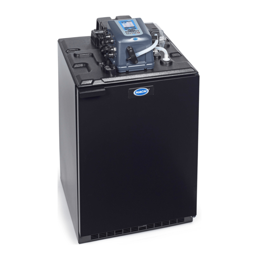
The sampler collects liquid samples at specified intervals and keeps the samples in a refrigerated cabinet. Use the sampler for a wide variety of aqueous sample applications and also with toxic pollutants and suspended solids.

- Refrigerator base unit
- Power supply
- Pump
- Controller
- Liquid detector
- Non-contacting liquid detector
- Refrigerated cabinet
Product components
Fire hazard. This product contains a flammable refrigerant. Do not damage or puncture the refrigeration circuit.
Personal injury hazard. Instruments or components are heavy. Use assistance to install or move.
The instrument weighs a maximum of 63.5 kg (140 lb). Do not try to unpack or move the instrument without sufficient equipment and people to do it safely. Use correct lifting procedures to prevent injury. Make sure that all used equipment is rated for the load, for example, a hand truck must be rated for a minimum of 68 kg (150 lb). Do not move the sampler when filled sample bottles are in the refrigerated cabinet.
Make sure that all components have been received. Refer to Figure 3. If any items are missing or damaged, contact the manufacturer or a sales representative immediately.

- Optional cover
- Refrigerated sampler
- Components for single-bottle option
- Components for multiple-bottle option
- Intake tubing, vinyl or PTFE-lined
- Strainer
- Tubing coupler2
- Supplied with controllers with the non-contacting liquid detector only.
Installation
Multiple hazards. Only qualified personnel must conduct the tasks described in this section of the document.
Site installation guidelines
 Explosion hazard. The instrument is not approved for installation in hazardous locations.
Fire hazard. This product contains a flammable refrigerant. Do not damage or puncture the refrigeration circuit.
- Only install the refrigerated sampler in an indoor location that is out of direct sunlight and away from heat sources.
- Make sure that the temperature at the location is in the specification range. Refer to Specifications.
- Install the sampler on a level surface. Adjust the sampler feet to make the sampler level. Refer to Figure 1 for the sampler dimensions.
- Make sure that all airflow openings in the instrument and in the structure (if applicable) are not blocked.
- Plumb a drain tube to the ½ in.-14 NPT female connector on the bottom of the sampler.
Prepare the sampler
- Clean the sample bottles
Clean the sample bottles and caps with a brush, water and a mild detergent. Flush the sample bottles with fresh water followed by a distilled water rinse. - Install a single bottle
When a single bottle is used to collect one composite sample, do the steps that follow. When multiple bottles are used, refer to Install multiple bottles.
When the bottle is full, the full bottle shut-off stops the sampling program. Install the sample bottle as shown in Figure 4.

- Install multiple bottles
When multiple bottles are installed, a distributor arm moves the sample tube over each bottle. Sample collection automatically stops when the specified number of samples are collected.- Assemble the sample bottles as shown in Figure 5. For eight or more bottles, make sure that the first bottle is near the bottle one indicator in the clockwise direction.

- Retainer for 24 1-L poly bottles
- Retainer for 24 350-mL glass bottles
- Bottle one indicator
- Bottle tray for 8 to 24 bottles
- Slot for bottle tray
- Floor of refrigerated sampler
- Front of sampler
- Insert (refrigerated sampler only)
- Put the bottle assembly in the sampler. For eight or more bottles, align the wires in the slots in the bottom tray.
- Assemble the sample bottles as shown in Figure 5. For eight or more bottles, make sure that the first bottle is near the bottle one indicator in the clockwise direction.


Plumb the sampler
Install the intake tube in the middle of the sample stream (not near the surface or bottom) to make sure that a representative sample is collected.
- For a sampler with the standard liquid detector, connect the tubing to the sampler as shown in Figure 6.

Note: When Teflon-lined tubing is used, use the tubing connection kit for Teflon-lined PE tubing. - For a sampler with the optional non-contacting liquid detector, connect the tubing to the sampler as shown in Figure 7.

Note: When Teflon-lined tubing is used, use the tubing connection kit for Teflon-lined PE tubing. - Install the intake tube and strainer in the main stream of the sample source where the water is turbulent and well-mixed.

- Strainer
- Vertical lift
- Make the intake tube as short as possible. Refer to Specifications for the minimum intake tubing length.
- Keep the intake tube at a maximum vertical slope so that the tube drains completely between samples.
Note: If a vertical slope is not possible or if the tube is pressurized, disable the liquid detector. Calibrate the sample volume manually. - Make sure that the intake tube is not pinched.


Electrical installation
Connect the sampler to power

Electrocution hazard. If this equipment is used outdoors or in potentially wet locations, a Ground Fault Circuit Interrupt (GFCI/GFI) device must be used for connecting the equipment to its main power source.
Fire hazard. Install a 15 A circuit breaker in the power line. A circuit breaker can be the local power disconnect, if located in close proximity to the equipment.
Electrocution hazard. Protective Earth Ground (PE) connection is required.

Electrocution hazard. Make sure that there is easy access to the local power disconnect.
Connect the power cords on the refrigerated sampler. Use a power line filter or connect the power cord for the controller to a different branch circuit to decrease the possibility of electrical transients.
Controller connections
Figure 9 shows the electrical connectors on the controller.

- Sensor 2 port (optional)
- Power supply port
- Sensor 1 port (optional)
- USB connector
- Rain gauge/RS485 port (optional)
- Auxilliary I/O port
- Distributor arm/Full bottle shut-off port
- Connect a Sigma 950 or FL900
If sample pacing is flow based, supply the controller with a flow input signal (pulse or 4–20 mA). Connect a Sigma 950 or an FL900 Flow Logger to the AUX I/O port.
As an alternative, connect a flow sensor to a sensor port. Refer to Connect a sensor.
Item to collect: Multi-purpose auxiliary full cable, 7 pin- Connect one end of the cable to the flow meter. Refer to the flow meter documentation.
- Connect the other end of the cable to the AUX I/O port on the controller.
Connect a non-Hach flow meter
To connect a non-Hach flow meter to the AUX I/O port, do the steps that follow.
Items to collect: Multi-purpose auxiliary half cable, 7 pin
- Connect one end of the cable to the AUX I/O port on the controller.
- Connect the other end of the cable to the flow meter. Refer to Figure 10 and Table 1.
Note: In some installations, it is necessary to connect external equipment to the Pulse input, Special output and/or Program Complete output with long cables. Since these are ground-referenced pulse interfaces, false signaling can be caused by transient ground differences between each end of the cable. High ground differentials are typical in heavy industrial environments. In such environments, it may be necessary to use third-party galvanic isolators (e.g., optocouplers) in line with the affected signal(s). For the Analog input, external ground isolation is typically not necessary because the 4–20 mA transmitter typically supplies isolation.


Table 1 Half cable wiring information
| Pin | Signal | Color3 | Description | Rating |
| 1 | +12 VDC power output | White | Power supply positive output. Only use with pin 2. | Battery power to the I/O module: 12 VDC nominal; Power supply to the I/O module: 15 at 1.0 A maximum. |
| 2 | Common | Blue | Negative return of power supply. When the power supply is used, pin 2 is connected to earth ground4. | |
| 3 | Pulse input or Analog input | Orange | This signal is a sample collection trigger from the flow logger (pulse or 4–20 mA) or a simple floating (dry) contact closure. | Pulse input—Reacts to a positive pulse with respect to pin 2. Termination (pulled low): pin 2 through a series 1 kΩ resistor and 10 kΩ resistor. A 7.5 zener diode is in parallel with the 10 kΩ resistor as a protection device. Analog input—Reacts to the analog signal that enters pin 3 and returns on pin 2. Input burden: 100 Ω plus 0.4 V; Input current (internal limit): 40 to 50 mA maximum5 Absolute maximum input: 0 to 15 VDC with respect to pin 2. Signal to make the input active: 5 to 15 V positive-going pulse6 with respect to pin 2, 50 millisecond minimum. |
| 4 | Liquid level input or Auxiliary control input | Black | Liquid level input—Start or continue the sampling program. A simple float level switch can supply input. Auxiliary control input—Start a sampler after the sampling program on another sampler ends. As an alternative, start a sampler when a trigger condition occurs. For example, when a high or low pH condition occurs, the sampling program starts. | Termination (pulled high): internal +5 V supply through an 11 kΩ resistance with a series 1 kΩ resistor and 7.5 V zener diode terminated to pin 2 for protection. Trigger: High to low voltage with a low pulse of 50 milliseconds minimum. Absolute maximum input: 0 to 15 VDC with respect to pin 2. Signal to make the input active: external logic signal with 5 to 15 VDC power source. The drive signal must be typically high. The external driver must be able to sink 0.5 mA at 1 VDC maximum at the logic low level. A logic high signal from a driver with a power source of more than 7.5 V will source current into this input at the rate of: I = (V – 7.5)/1000 where I is the source current and V is the power supply voltage of the driving logic. Dry contact (switch) closure: 50 millisecond minimum between pin 4 and pin 2. Contact resistance: 2 kΩ maximum. Contact current: 0.5 mA DC maximum |
| 5 | Special output | Red | This output goes from 0 to +12 VDC with respect to pin 2 after each sample cycle. Refer to the Mode setting of the hardware settings for the AUX I/O port. Refer to the AS950 operations documentation. | This output has protection against short circuit currents to pin 2. External load current: 0.2 A maximum Active high output: 15 VDC nominal with AC power to the AS950 controller or a 12 VDC nominal with battery power to the AS950 controller. |
| 6 | Program Complete output | Green | Typical state: open circuit. This output goes to ground for 90 seconds at the end of the sampling program. Use this output to start another sampler or to signal an operator or data logger at the end of the sampling program. | This output is an open drain output with 18 V zener clamp diode for over-voltage protection. The output is active low with respect to pin 2. Absolute maximum ratings for the output transistor: sink current = 200 mA DC maximum; external pull-up voltage = 18 VDC maximum |
| 7 | Shield | Silver | The shield is a connection to earth ground when AC power is supplied to a sampler to control RF emissions and susceptibility to RF emissions. | The shield is not a safety ground. Do not use the shield as a current carrying conductor. The shield wire of cables that are connected to the AUX I/O port and are more than 3 m (10 ft) should connected to pin 7. Only connect the shield wire to earth ground at one end of the cable to prevent ground loop currents. |
- The wire color refers to the colors of multi-purpose cables. Refer to Accessories.
- All mains powered equipment that connects to the controller terminals must be NRTL listed.
- Long-term operation in this state voids the warranty.
- Source impedance of the driving signal must be less than 5 kΩ.
Connect a sensor
To connect a sensor (e.g., pH or flow sensor) to a sensor port.

Startup
Set the instrument to on
The refrigerator starts after a 5-minute delay when power is supplied to the sampler. The refrigerator continues to operate when the controller is set to off or the power is removed from the controller.
Push the POWER key on the controller to set the controller to on.
To set the refrigerator to off, push the POWER key on the controller. Then, disconnect the two power cords on the refrigerated sampler.
Preparation for use
Install the analyzer bottles and stir bar. Refer to the operations manual for the startup procedure.
Maintenance
Multiple hazards. Only qualified personnel must conduct the tasks described in this section of the document.
Electrocution hazard. Remove power from the instrument before doing maintenance or service activities.
 Fire hazard. This product contains a flammable refrigerant. Do not damage or puncture the refrigeration circuit. Do not use a mechanical device or other procedure to increase the speed of a defrost cycle.
 Biohazard exposure. Obey safe handling protocols during contact with sample bottles and sampler components.
Multiple hazards. The technician must make sure that the equipment operates safely and correctly after maintenance procedures.
NOTICE
Do not disassemble the instrument for maintenance. If the internal components must be cleaned or repaired, contact the manufacturer.
Clean the instrument
Fire hazard. Do not use flammable agents to clean the instrument.
NOTICE
Do not clean the controller compartment heater with liquids of any kind.
If water is not sufficient to clean the controller and the pump, disconnect the controller and move the controller away from the sampler. Allow sufficient time for the controller and pump to dry before the parts are re-installed and put back into service.
Clean the sampler as follows:
- Refrigerator — clean the condenser fins and coils as needed with a brush or vacuum.
Note: The controller sets the temperature of the evaporator for frost-free operation. Do not use a mechanical device or other procedure to increase the speed of a defrost cycle. - Sampler cabinet and tray — clean the internal and external surfaces of the sampler cabinet with adamp cloth and mild detergent. Do not use abrasive cleaners or solvents.
Replace the desiccant
A desiccant cartridge in the controller absorbs moisture and prevents corrosion. Monitor the desiccant color through the desiccant window. Refer to Figure 12. Fresh desiccant is orange. When the color is green, replace the desiccant.
- Unscrew and remove the desiccant cartridge.

- Plug
- Desiccant tube
- O-ring
- Desiccant window
- Remove the plug and discard the spent desiccant.
- Fill the desiccant tube with fresh desiccant.
- Install the plug.
- Apply silicone grease to the O-ring.
- Install the desiccant tube in the controller.

Pump maintenance
 Pinch hazard. Remove power from the instrument before maintenance or service activities are done.
Replace the pump tubing
NOTICE
Use of tubing other than that supplied by the manufacturer can cause excessive wear on mechanical parts and/or poor pump performance.
Examine the pump tubing for wear where the rollers rub against the tubing. Replace the tubing when the tubing shows signs of wear.
Pre-requisites:
- Pump tubing—pre-cut or bulk 4.6 m or 15.2 m (15 ft or 50 ft)
- Disconnect the power to the controller.
- If the bulk tubing is used, cut the tubing and add alignment dots.

- To intake tubing
- Alignment dots
- To fitting on sampler base
- Length for controller with standard liquid detector
- Length for controller with optional non-contacting liquid detector
- Length inside the pump
- Length for the refrigerated sampler
- Length for refrigerated sampler and controller with standard liquid detector
- Length for refrigerated sampler and controller with non-contacting liquid detector
- Remove the pump tubing as shown in the illustrated steps that follow.
- Clean the silicone residue from the interior of the pump housing and from the rollers.
- Install the new pump tubing as shown in the illustrated steps that follow.


Clean the rotor
Clean the rotor, pump tube tracks and pump housing with a mild detergent. Refer to Replace the pump tubing and the illustrated steps that follow.

Replace the distributor arm tube
The distributor arm moves over each bottle during multiple bottle sampling. Replace the tube in the distributor arm when the tube is worn. Make sure that the correct tube is used for the correct distributor and distributor arm.
Note: The distributor tubing is not the same as the pump tubing. The pump tubing installed in the distributor assembly can damage the distributor. Also, samples can be missed because the distributor arm cannot move easily.
- Remove the tube from the distributor arm and from the ceiling of the sampler cabinet.
- Insert the new tube into the distributor arm. Extend the tube past the end of the distributor arm 4.8 mm (3/16 in.) or 19 mm (3/4 in.) as shown in item 1 of Figure 14.

- Tube extension
- Nozzle
- Distributor arm
- Distributor arm lengths: 152.4 mm (6.0 in.), 177.8 mm (7.0 in.) or 190.8 mm (7.51 in.)
- Distributor motor
- Shaft
- Distributor tube
- Insert the other end of the tube into the fitting on the ceiling of the sampler cabinet.
- Complete the diagnostic test for the distributor to make sure that the operation is correct.

Replace the power supply
 Fire hazard. Use only the external power supply that is specified for this instrument.
To replace the power supply for the refrigerated sampler.

Troubleshooting
General troubleshooting
Table 2 shows causes and corrective actions for several common problems.
Table 2 Troubleshooting table
| Problem | Possible cause | Solution |
| No instrument power | Problem with the main power source. | Make sure that AC power gets to the electrical outlet. |
| Defective power supply (refrigerated sampler only) | Replace the power supply. | |
| Defective controller | Contact technical support. | |
| Sampler does not have sufficient lift. | Strainer is not completely submerged. | Install the shallow depth strainer (2071 or 4652). |
| Intake tube has a leak. | Replace the intake tube. | |
| Pump tube is worn. | See Replace the pump tubing. | |
| Pump roller assembly is worn. | Contact technical support. | |
| Sample volume is not correct. | Incorrect volume calibration | Repeat the volume calibration. |
| Incorrect tube length is specified in the sampling program. | Make sure that the correct tube length is in the sampling program. | |
| Intake tube does not purge completely. | Make sure that the intake tube is as vertical and as short as possible. | |
| Strainer is not completely submerged. | Install the shallow depth strainer (2071 or 4652). | |
| Worn pump tubing and/or roller assembly. | Replace the pump tube and/or roller assembly. | |
| The liquid detector is disabled. | Turn the liquid detector on and complete a volume calibration. | |
| Liquid detector does not operate properly. | Calibrate the liquid detector with the same liquid that is sampled. |
Replacement parts and accessories
Personal injury hazard. Use of non-approved parts may cause personal injury, damage to the instrument or equipment malfunction. The replacement parts in this section are approved by the manufacturer.
Note: Product and Article numbers may vary for some selling regions. Contact the appropriate distributor or refer to the company website for contact information.
Bottle kits
| Description | Quantity | Item no. |
| Single bottle kits (includes bottle and full bottle shut off): | ||
| 10-L (2.5-gal) poly bottle and full bottle shut off | 1 | RF010030 |
| 10-L (2.5-gal) glass bottle and full bottle shut off | 1 | RF010025 |
| 21-L (5.5-gal) poly bottle and full bottle shut off | 1 | RF010060 |
| Multi-bottle kits (include bottle, retainer and distributor arm): | ||
| 10-L (2.5-gal) poly bottles, retainer and distributor arm | 4 | RF040030 |
| 350-mL (11.8-oz) glass bottles, retainer and distributor arm | 24 | RF240350 |
| 1-L (33.8-oz) poly bottles, retainer and distributor arm | 24 | RF241000 |
Bottle sets
| Description | Quantity | Item no. |
| Bottle, 10-L (2.5-gal) glass with cap | 1 | 6559 |
| Bottle, 10-L (2.5-gal) poly with cap | 1 | 1918 |
| Bottle, 21-L (5.5-gal) poly with cap | 1 | 6498 |
| Bottle set, 1-L (33.8-oz) poly with caps | 24 | 737 |
| Bottle set, 350-mL (11.8-oz) glass with caps | 24 | 732 |
| Bottle set, 2.3-L (0.6-gal) poly with caps | 8 | 657 |
| Bottle set, 1.9-L (0.5-gal) glass with caps | 8 | 1118 |
| Bottle set, 10-L (2.5-gal) glass with caps | 4 | 2317 |
| Bottle set, 10-L (2.5-gal). poly with caps | 4 | 2315 |
| Bottle set, 10-L (2.5-gal) glass with caps | 2 | 2318 |
| Bottle set, 10-L (2.5-gal) poly with caps | 2 | 2316 |
Replacement parts
| Description | Quantity | Item no. |
| AS950 controller retrofit kit, refrigerated sampler | 1 | 9505000US |
| Bottle tray, 8 to 24 bottles | 1 | 1511 |
| Desiccant, refill | 0.56 kg (1.5 lb) | 8755500 |
| Desiccant cap assembly | 1 | 8754900 |
| Desiccant tube | 1 | 8742100 |
| Desiccant tube assembly | 1 | 8741500 |
| Desiccant tube assembly with silicone grease packet | 1 | 8755600 |
| Insert, refrigerated sampler | 1 | 2038 |
| Pump cover | 1 | 8755400 |
| Pump, replacement assembly | 1 | 6262000 |
| Full bottle shut-off | 1 | 8996 |
| Power supply, North America, NEMA 5-15P plug, 103.5–124.5 VAC | 1 | 8754500US |
| Power supply, Europe, CCE 7/7 plug, 207–253 VAC | 1 | 8754500EU |
| Power supply, Australia, AS3112 plug, 207–253 VAC | 1 | 8754500AU |
| Retainer for 24 1-L poly bottles | 1 | 1322 |
| Retainer for 24 350-mL glass bottles | 1 | 1056 |
| Tubing, pump, refrigerated sampler with non-contacting liquid detector | 7.6 m (25 ft) | 9501400 |
| Tubing, pump | 4.6 m (15 ft) | 4600-15 |
| Tubing, pump | 15.2 m (50 ft) | 4600-50 |
| Tubing, black, soft PVC, intake 10 mm ID, 15 mm OD | 7.8 m (25.5 ft) | 6633500 |
| Tubing, black, soft PVC, intake 10 mm ID, 15 mm OD | selected when ordered | 6627200 |
| Tubing, PTFE-lined intake 3/8-in. | 3 m (10 ft) | 921 |
| Tubing, PTFE-lined intake 3/8-in. | 7.6 m (25 ft) | 922 |
| Tubing, PTFE-lined intake 3/8-in. | 30.5 m (100 ft) | 925 |
| Tubing, vinyl intake 3/8-in. | 7.6 m (25 ft) | 920 |
| Tubing, vinyl intake 3/8-in. | 30.5 m (100 ft) | 923 |
| Tubing, vinyl intake, 3/8-in. | 152.4 m (500 ft) | 924 |
| Tubing connection kit for PTFE-lined PE tubing | 1 | 2186 |
Accessories
| Description | Item no. |
| Assembly, A/C power backup, 3P, 406.4 mm (16 in.) CBL | 8757400 |
| Cover | 8963 |
| Distributor assembly with arm for 24 bottles | 8562 |
| Distributor assembly with arm for 8 bottles | 8565 |
| Distributor assembly with arm for 2 or 4 bottles | 8568 |
| Distributor arm for assembly 8562, with tubing | 8563 |
| Distributor arm for assembly 8565, with tubing | 8566 |
| Distributor arm for assembly 8568, with tubing | 8569 |
| Distributor arm for assembly 8562 | 1782 |
| Distributor arm for assembly 8565 | 1785 |
| Distributor arm for assembly 8568 | 1789 |
| Distributor arm tubing, 571.5 mm (22.5-in.), for assembly 8562 (arm 1782) | 8564 |
| Distributor arm tubing, 571.5 mm (22.5-in.), for assembly 8565 (arm 1785) | 8564 |
| Distributor arm tubing, 520.7 mm (20.5-in.), for assembly 8568 (arm 1789) | 8570 |
| Lockable hasp on refrigerator door | 2143S |
| Power Supply, 3 pin connector, 100-120 VAC | 8754500US |
| Retainer for 2 or 4 10-L (2.5-gal) glass/poly bottles | 2038 |
| Retrofit Kit (U.S.) | 9505000US |
| Tubing for peristaltic pump, pre-cut for refrigerated sampler | 8753800 |
| Tubing Extension | 3527 |
| Tubing Support | 8986 |
| AV9000 interface, subAV sensor | 8531300 |
| Cable, auxiliary, cascade sampling or synchronized sampling | 9505100 |
| Cable, auxiliary, Sigma 950 to AUX port, 2.7 m (9 ft) | 8528400 |
| Cable, auxiliary, Sigma 950 to AUX port, 7.6 m (25 ft) | 8528401 |
| Cable, auxiliary, multi-purpose half, 7 pin, 2.7 m (9 ft) | 8528500 |
| Cable, auxiliary, multi-purpose half, 7 pin, 7.6 m (25 ft) | 8528501 |
| Cable, Cascade/Syncho cable | 9505100 |
| Cable, FL900 logger to AUX port, 7 pin, 2.7 m (9 ft) | 9500700 |
| Cable, FL900 logger to AUX port, 7 pin, 2.7 m (25 ft) | 9500701 |
| Cable, pHD sensor, used with DPD2P1 | 9501200 |
| Cable, USB, Type A–A, 2 m (6.5 ft) | 9504700 |
| Flow-thru module | 2471 |
| Full-bottle shutoff | 8847 |
| IO9004 module | 9494600 |
| IO9001 module (one high voltage relay) | 9494500 |
| Junction box with auxiliary cable | 9501000 |
| Rain gauge, tipping bucket, includes 30.5 m (100 ft) 7-pin cable | 8542800 |
| Sensor, pHD, digital, used with 9501200 | DPD2P1 |
| Sensor, US9001, downlooking ultrasonic | 9487100 |
| Sensor, US9001B, downlooking ultrasonic | 9088800 |
| Sensor, US9003, in-pipe ultrasonic | 9497300 |
| Sensor, subAV, used with AV9000 interface | 77065-030 |
| Silicone grease, 7 g (0.25 oz) | 000298HY |
| Strainer, all 316 stainless steel, 152 mm long x 10.3 mm OD (6.0 in. long x 0.406 in. OD) | 2071 |
| Strainer, all 316 stainless steel, 201.7 mm long x 25.4 mm OD (7.94 in. long, x 1.0 in. OD) | 2070 |
| Strainer, stainless steel, 99.1 mm long x 10.3 mm OD (3.9 in. long x 0.406 in. OD) | 4652 |
| Strainer, PTFE/stainless steel, 139.7 mm long x 22.2 mm OD (5.5 in. long x 0.875 in. OD) | 926 |
| Strainer, PTFE/stainless steel, 279.4 mm long x 22.2 mm OD (11.0 in. long x 0.875 in. OD) | 903 |
| Adapter fitting, tubing | 9503200 |
Documents / ResourcesDownload manual
Here you can download full pdf version of manual, it may contain additional safety instructions, warranty information, FCC rules, etc.
Advertisement


Need help?
Do you have a question about the AS950 and is the answer not in the manual?
Questions and answers