Marshall 1974X Manual
- Quick start manual (28 pages) ,
- Owner's manual (5 pages) ,
- Product catalogue (32 pages)
Advertisement
SPECIFICATION
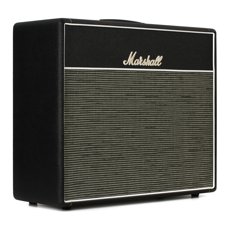
The 18W 1974X is a re-issue of the 1974 produced between 1966 and 1968. Just like the original, the 1974X is valve driven and is carefully handwired in the UK. The Celestion G12M-20 Greenback has been 'aged' to get as close as possible to that vintage, worn in sound of the original.
| Power | 18W |
| Valves | 2 x ECC83, 1 x ECC83 (phase splitter), 2 x EL84, 1 x EZ81 (rectifier) |
| Channels | 2 |
| Equalisation | 2 x tone controls (1 per channel) |
| Outputs | 2 x 1/4" jack speaker outputs, selectable 16Ω/8Ω/4Ω load |
| Effects loop | No |
| Speaker config. | 1 x 12" |
| Speaker model | Celestion Heritage Greenback G12M-20 (20W, 15Ω) |
| Unit weight | 19kg |
| Unit width | 610mm |
| Unit height | 535mm |
| Unit depth | 230mm |
FRONT PANEL FUNCTIONS

- INDICATOR
The power indicator will light when the amp's mains power is switched on. - STANDBY SWITCH
The standby switch is used in conjunction with the power switch to 'warm up' the amp before use.
Always turn the power on for two minutes before switching the standby switch to the 'on' position.
The standby switch should be set to the 'off' position during breaks in performances instead of leaving the amp on full power. - POWER SWITCH
Turns the amp on and off. - SPEED
Controls the speed at which the tremolo effect oscillates. - INTENSITY
Controls the depth of the tremolo effect's oscillation.
Note: tremolo will only work when playing through channel 2. - TONE CONTROL (CHANNEL 2)
Adjusts the tonal character of channel 2. Turning this control clockwise increases the amount of high frequencies (treble) present in the sound.
VOLUME CONTROL (CHANNEL 2)
Controls the volume of channel 2.
8 & 9. CHANNEL 2 INPUTS
These are the guitar inputs for channel 2. The top one is the 'high sensitivity' input for this channel. The bottom one is the 'low sensitivity' input (6dB lower).
- TONE CONTROL (CHANNEL 1)
This controls the tonal character of channel 1. Turning the tone control clockwise increases the amount of high frequencies (treble) present in the sound. - VOLUME CONTROL (CHANNEL 1)
Controls the volume for channel 1.
12 & 13. CHANNEL 1 INPUTS
These are the guitar inputs for this channel and both are identical.
Note: some guitar players prefer to mix the two channels together by plugging a guitar into the top (high sensitivity) input of the Tremolo channel and running a short, screened guitar cable from the Tremolo channel's bottom (low sensitivity) input to either one of channel 1's two identical inputs. The Tremolo channel must be used as the primary channel.
REAR PANEL FUNCTIONS

- TREMOLO FOOTSWITCH JACK
This is where the supplied Tremolo on/off footswitch is plugged in.
2 & 3. SPEAKER OUTPUTS
Connect one or two speaker cabinets here using 1/4" jack speaker cables.

Always ensure the output impedance selector is set to the appropriate impedance for the load of your setup (speaker cabinets). Never use this amp without a speaker or load.
- OUTPUT IMPEDANCE SELECTOR
Matches the amp's output to the load impedance. Ensure the amp is completely powered down before turning the selector.
The impedance selected on the amp must match the total impedance of the internal speaker or external speaker cabinet(s) being used.- When using the combo's internal speaker only, the impedance selector must be set to 16Ω.
- If an additional 16Ω extension speaker cabinet is used in conjunction with the internal speaker the impedance selector should be set to 8Ω.
Note: an extension speaker cabinet with an impedance of less than 16Ω should not be used in conjunction with the internal speaker.
Failure to comply with these points may result in damage to the amp.
- MAINS FUSE
The correct value of the mains fuse is specified on the rear panel. - H.T. FUSE
The correct value of the H.T. fuse is specified on the rear panel. - POWER INLET
The supplied mains power lead is connected here. The mains input voltage rating that your amp has been built for is shown on the rear panel.
SAFETY INSTRUCTIONS
Please read this manual carefully before plugging in. Follow all instructions and heed all warnings.
Please refer to full details in separate Important Safety Instructions leaflet (document number CATS-00158).
MAINS ELECTRICITY SUPPLY AND OUTPUT IMPEDANCE
The specific mains input voltage rating that your amp has been manufactured for is indicated on the rear panel of the amp. Your amp is provided with a detachable mains (power) lead, which should be connected to the mains input socket on the rear panel of the amp.
The correct value and type of mains fuse is specified on the rear panel of the amp. Never attempt to bypass the fuse or fit one of the incorrect value or type.
The output impedance selector should be set to the total impedance of the speaker cabinet(s) (or load) being used.
If you have any doubt regarding your mains electricity supply or the impedance of speaker cabinet(s), please seek help from a qualified engineer – your Marshall dealer can help you with this.
Your amp must be switched off and disconnected from the mains electricity supply before you:
- check and/or change any fuse; and/or
- change the output selector for a different setting.
Failure to comply with any of the points above may damage your amp.
IMPORTANT SET UP INFORMATION
- Set the output impedance selector to the impedance of the combined load of the speaker cabinet(s) you will be using.
- Check that the internal speaker and/or extension cabinets that you want to use are plugged into the speaker outputs correctly.
Note: There are two parallel speaker output jack sockets provided for connection to the internal speaker and/or an external load, e.g. speaker extension cabinet(s). The amp is supplied with the internal speaker connected to one of the speaker output jack sockets. More information on impedance can be found later in this guide.
![]()
Failure to do the above may damage your amp. When connecting a speaker cabinet make sure that you use a proper speaker cable. Never use a screened (shielded) guitar cable for this purpose. - Ensure that both the power switch and standby switch are set to the off position.
- Connect the supplied mains (power) lead into the power inlet on the rear panel first and then into an electricity outlet.
- Ensure that any master, volume and/or output level controls on the front panel are set to zero.
- Plug your guitar into one of the inputs on the front panel.
- Turn the power switch on and wait a couple of minutes.
- Turn the standby switch on.
- Turn the volume up to your preferred level and you're ready to play.
TRANSPORTING YOUR EQUIPMENT
Please ensure that your amp is switched off, unplugged from the mains electricity supply and all removable cables have been disconnected from your equipment before attempting to move it. Only move the amp on its own. Do not attempt to move it while it is stacked on top of a cabinet or other equipment.
Documents / Resources
References
Download manual
Here you can download full pdf version of manual, it may contain additional safety instructions, warranty information, FCC rules, etc.
Advertisement


Need help?
Do you have a question about the 1974X and is the answer not in the manual?
Questions and answers