Advertisement
Introduction
For the past two decades, one name has been synonymous with the best in rock amplification. Marshall has now become a household name throughout the world as a symbol of precision acoustic engineering to be relied upon, not only for superlative sound quality, but also for high performance night after night.
Each amplifier chassis is constructed from steel, precision cut, punched, hent and seam welded to form a substantial, rigid foundation, strong enough to take all the knocks of the road.
All electronic components are selected and tested to outperform their required functions, and the electrical hardware, such as switches, selectors, etc., comply to most international safety standards, to ensure the user is safe from the risk of electric shock.
The same applies to both the mains and output transformer that are designed and built to withstand full output for hour upon hour, To complete the electrical specification all valves are selected from the finest grades available.
After testing and adjusting, each chassis is assembled into cabinets made from finest quality birch ply, corner locked and r.f. bonded for immense strength and longevity.
After the black P.V.C. covering is bonded and stretched into place, A.B.S. corner protectors and air vents are riveted into position, creating a cabinet that is manufactured to an equal standard as that of the chassis.
The Master Volume and Super Lead amplifiers and combos cover the whole musical spectrum from the small practice amp to the full stage set-up, forming the basis of the classic Marshall range, which has become so renowned throughout the world.
Jim Marshall (Products) Ltd. operate a policy of continuous development and reserve the right to change specifications without prior notice.
Front Panel Functions
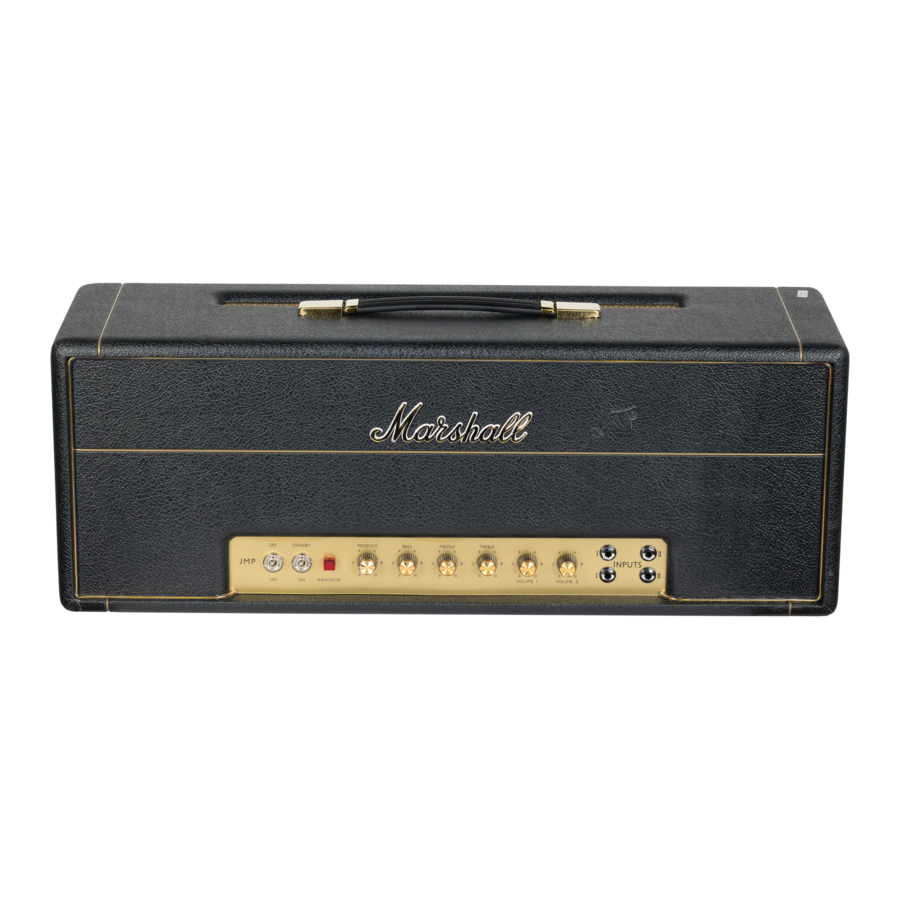
1987, 1959

- Power Switch
Controls total mains power to amplifier. - Standby Switch
Controls H.T. supply to amp valves. Allows the filaments to remain heated during breaks. - Channel 2 Input Jacks
Connects instrument to amplifier. Top input high power, bottom input low power. - Channel 1 Input Jacks
Top input high gain, bottom input low gain. This channel is treble boosted, therefore brighter than channel 2. With guitar plugged into channel l high input, amp may be linked to other amps by linking from low input channel 1 to high input channel on next Marshall amp. - Channel 2 Volume Control
Controls the overall output level of channel 2. - Channel 1 Volume Control
Controls the overall output of channel 1. - Treble Control
Controls the high frequency content of the amplifier. - Middle Control
Controls the middle register of the amplifier. - Bass Control
Controls the low frequency content of the amplifier. - Presence Control
Controls additional boost to the upper frequencies to add crispness and liveliness.
2204, 2203, 4010, 4104, 4103

- Power Switch
Controls total mains power to amplifier. - Standby Switch
Controls H.T. supply to amp valves. Allows the filaments to remain heated during breaks. - High & Low Input Jacks
Connects instrument to amplifier (high input gives more volume than low input). - Pre-amp Volume Control
Controls the volume of the pre-amp hence the amount of overdrive, i.e. when control is on full, maximum overdrive will be achieved. - Master Volume Control
Controls the overall output of the amplifier. - Treble Control
Controls the high frequency content of the amplifier. - Middle Control
Controls the middle register of the amplifier and at high levels will also modify the treble and bass. - Bass Control
Controls the low frequencies of the amplifier. - Presence Control
Controls additional boost to the upper frequencies of the overall sound and adds crispness and liveliness.
5010, 5002, 5005

- High Input
Connects instrument to amplifier (high powered input). - Low Input
Connects instrument to amplifier (low powered input). - Pre-amp Volume
Controls the level of pre-amplification (high settings for overdrive, low settings for cleaner sound). - Master Volume
Controls the overall output level of the amplifier. - Control
Controls the high frequency content of the amplifier. - Middle Control
Controls the middle register of the amplifier. - Bass Control
Controls the low frequencies of the amplifier. - Presence Control
Controls additional boost to the upper frequencies of the overall sound and adds crispness and liveliness (not included on models 5002 and 5005). - Headphone Line-out Jack Socket
For linking headphones, insertion of jack hallway mutes speaker and gives headphone signal. Full insertion of jack gives line-out. - Mains Power Switch
ON/OFF for mains power to amplifier.
NOTE! On models 5005 and 5002 the mains lead is attached. On model 5010 the mains lead is plugged into the socket on the back panel of the amplifier.
4001

- Input
Connects instrument to amplifier. - Gain Control
Controls input level (high settings for overdrive, lower settings for clean). - Treble Control
Controls the high frequency content of the amplifier. - Middle Control
Controls the mid range of the amplifier. - Bass Control
Controls the low frequencies of the amplifier. - Output Level Control
Controls the overall volume level of the amplifier. - Standby Switch
Controls H.T. supply to amp valves allowing the filaments to remain heated during breaks. - Power Switch
Controls total mains power to amplifier.
Rear Panel Functions
1987, 1959, 2204, 2203, 4010, 4104, 4103

- H.T. Fuse
See label for correct value.
Only use correct value fuse.
(Please note, on models 1987, 2204, 4104 and 4010 this item is reversed with component 12.) - Mains Fuse
See label for correct value.
Only use correct value fuse.
(Please note, on models 1987, 2204, 4104 and 4010 this item is reversed with component 11.) - Mains Input
Connects amplifier to power supply.
(Please note, on models 1987, 2204, 4104, and 4010 the position of this component is at the extreme of the chassis.) - Mains Selector
Matches amplifier output transformer to the incoming mains voltage. - Output Selector
Matches amplifier output transformer impedance to loudspeaker load impedance, i.e. 4/8/16 ohms. (Speaker impedance usually marked on cabinet), if in doubt check with supplier. - Loudspeaker Output Jacks
Parallel connected jacks for loudspeaker connections.
Speaker load must always be connected. If one or both sockets are used, total impedance must be matched to selector and must not be less than 4 ohms. - D.I. Output
Jack socket carrying low level version of amplifier output, suitable for connection to recording and P.A. mixing desks, or into slave amplifying systems.
4001

- Mains Input
Connects the amplifier to mains power supply. - Mains Fuse
See label on the back of the amp for current fuse value. - Balanced Line-out Socket
XLR type socket for connection to balanced line outboard equipment such an mixing console, etc., fully floating and giving 0dBm. output. - Speaker Output
Output for connection of internal or external loudspeaker 8 ohm nominal impedance giving 15 watts R.M.S. - Headphone Output
Output for headphones (only operative when speaker is disconnected), alternatively the internal speaker may be connected to this output for attenuated output. - Line-out
Unbalanced line-out for connecting the amplifier to unbalanced outboard equipment such as slave/speaker systems, etc.
Operational Functions
Note! Before switching on this unit it must be correctly earthed.
The super lead amplifiers 1987 and 1959 provide a very powerful rock sound. At lower levels the sound remains fairly clean, as the volume controls (5 or 6), are turned up, the natural distortion of the valve amp comes in. The tone may be shaped with controls 7, 8, 9 and 10. These controls work in conjunction with each other, hence it may be necessary to adjust more than one control to achieve the degree of variation required.
The master volume range will provide the overdriven sound at lower volumes by turning pre-amp control number 4 to maximum with master volume control number 5 at a lower level. For cleaner sounds, the pre-amp control (4), should be kept at a lower level than master volume control (5). The tone being set in the same way as models 1987 and 1959.
5010, 5002, 5005
Connect the guitar to input (1 or 2). The high input for louder, more distorted playing or the low input for a cleaner, less distorted sound. The pre-amplifier control (3), should he set to achieve the type of overdrive required - in conjunction with the Master Volume (4). For clean sounds, the Master Volume (4), should be set high and the pre-amp (3), low, For distorted sounds the pre-amp (3), should be set high and the Master Volume (4), should be lower - depending on the overall volume required. Set the tone controls (5, 6 and 7), to achieve type of sound required, using the presence control (8), where applicable, to further colour the sound.
4001
Connect the amplifier to the mains by using lead provided into socket (9). Switch on power switch (8), and set amp controls to zero. Connect the guitar to
input (1), and switch on standby (7).
Many different sounds can be achieved using the tone and volume controls. For overdrive, gain control (2), should be kept higher than output level (6). A variety of cleaner sounds can be achieved by keeping output level (6), higher than gain control (2).
The speaker may be disconnected without any damage to the amplifier section allowing the amp to be used as a valve pre-amplifier via the line out socket (14). The internal speaker can be connected to the headphone socket (13), which gives a very low signal through the speaker - allowing the amp to be used at maximum volume and giving full-bodied valve distortion. The internal speaker must be disconnected (12), to allow the headphone socket (13), to be used with headphones.
Diagram for linking models 1959 or 1987

- Ensure internal or external loudspeakers are connected (16), and properly matched to the amplifier by correct usage of the impedance selector (15).
- Turn the volume controls to zero.
- Check that mains settings (14), correspond to mains supply and connect the amplifier to socket (13).
- Switch power on (1), and allow valves to heat up to working temperature.
- Connect instrument to input jack (3 or 4).
- Switch standby on (2).
Specification
Measured at 1KHz. Controls set to maximum, top input unless otherwise stated.
1959
| Input Sensitivity | Channel 1 1mV. overload level 250mV. Channel 2 1.5mV. overload level 250mV. Bottom inputs have a 6dB. attenuation in sensitivity. |
| Power Output | Typical power at clipping, measured at 1KHz., average distortion 4% 115 watts R.M.S. into 4, 8, 16 ohms. Typical output power at 10% distortion 170 watts into 4 ohms. |
| Tone Range | Channel 1 has a 10dB/decade rising treble slope with automatic low volume brightness circuit. Channel 2 has flat response. Treble 10KHz - 35dB. Middle 600Hz - 9.5dB. Bass 50Hz - 15dB. Presence 3KHz - 6dB. |
| Power Supply Requirements | Mains input 120/220/240v. a.c. 40/60Hz. Max, consumption -- 375 watts. Mains fuse 120v - T4A. 220/240v - T2A. H.T. Fuse TIA. |
| Valve Complement | Pre-amp and phase splitter valves V1, 2, 3 - ECC83, 12AX7. Output power valves V4, 5, 6, 7 - EL34, KT77. |
1987
| Input Sensitivity | Channel 1 1mV overload level 150mV. Channel 2 1.5mV overload level 150mV. Bottom inputs have a 6dB, attenuation in sensitivity. |
| Power Output | Typical power at clipping, measured at 1KHz, average distortion 3% in excess of 50 watts R.M.S. into 4, 8, or 16 ohms. Typical output power at 10% distortion 90 watts into 16 ohms. |
| Tone Range | Channel 1 has a 10dB/decade rising treble slope with automatic low volume brightness circuit. Channel 2 has flat response. Treble 10KHz - 26dB. Middle 600Hz - 9.5dB. Bass 50Hz - 15dB. Presence 3KHz - 6dB. |
| Power Supply Requirements | Mains input 120/220/240v. a.c. 40/60Hz. Max. consumption - 175 watts. Mains fuse 120v - T3A. 220/240v - T2A. H.T. Fuse T500mA. |
| Valve Complement | Pre-amp and phase splitter valves V1, 2, 3 - ECC83, 12AX7. Power output valves V4, 5 - EL34, KT77. |
2203, 4103
| Input Sensitivity | Low sensitivity input -- 10mV. overload level infinity. High sensitivity input - 0.15mV. overload level max. 150 mV., 1 mV. min. |
| Power Output | Typical power at clipping, measured at 1KHz., average distortion 4% 115 watts R.M.S. into 4, 8, 16 ohms. Typical output power at 10% distortion 170 watts into 4 ohms. |
| Tone Range | Treble 10KHz. - 35dB. Middle 600Hz. - 9.5dB. Bass 50Hz. - 15dB, Presence 3KHz. - 6dB. |
| Power Supply Requirements | Mains input 120/220/240v. a.c. 40/60Hz. Max. consumption - 375 watts. Mains fuse 120v. - T4A. 220/240v. - T2A. H.T. fuse T1A. |
| Valve Complement | Pre-amp and phase splitter valves V1, 2, 3 - ECC83, 12AX7. Power output valves V4, 3, 6, 7 - EL34, KT77. |
2204, 4104, 4010
| Input Sensitivity | Low sensitivity input 17 mV. overload level infinity. High sensitivity input - 0.15mV. overload level max. 150 mV. min. 1mV. |
| Power Output | Typical power at clipping, measured at 1KHz., average distortion 3% - in excess of 50 watts R.M.S. into 4, 8, or 16 ohms. |
| Tone Range | Treble 10KHz - 32dB. Middle 500Hz. - 9.5dB. Bass 50Hz. - 15dB. Presence 3KHz. - 6dB. |
| Power Supply Requirements | Mains input 120/220/240v. a.c. 40/60Hz Max. consumption - 175 watts. Mains fuse 120v. - T3A. 220/240v. - T2A. |
| Valve Complement | Pre-amp and phase splitter valves V1, 2, 3 - ECC83, 12AX7. Output power valves V4, 5 - EL34 - 6550. |
5005
| Input Sensitivity | Low 0.2m V. High 0.1mV |
| Tone | Treble 5KHz. — 30dB. mid down. Middle 450Hz. — 17dB. treble and bass full. Bass 100Hz. — 25dB. mid down. |
| Output | 12 watts into 8 ohm 10 inch Celestion loudspeaker. Min. handling power 25 watts. H.P. output approximately 100mW. Line-out approximately 600 mV. R.M.S. at clipping. |
| Power Supply | Internally set for 120/220 or 240v. 40/60Hz. 35vA. |
| Mains Fuse | 120v. - T500mA. 220/240v, - T160mA. |
5002
| Input Sensitivity | Low 0.2mV. High 0.1mV |
| Tone | Treble 5KHz. - 30dB. mid down. Middle 450Hz. - 17 dB. treble and bass full. Bass100Hz. - 25dB. mid down. |
| Output | 20 watts into 8 ohm 10 inch Celestion loudspeaker. Min. handling power 35 watts. H.P. output approximately 100mW. Line-out approximately 600 mV. R.M.S. at clipping. |
| Power Supply | Internally sell for 120/220 or 240v. 40/60Hz. 50vA. |
| Mains Fuse | 120v. - 1500mA 220/240v. - T500mA. |
5010
| Sensitivity | All controls maximum 0.35mV. R.M.S. Maximum input level 1.7v. R.M.S. |
| Tone Swing | Bass 100H7. - 15dB. Middle 500Hz. - 25dB. Treble 16dB. (mid max.) 42dB. (mid max.) |
| Power Output | 30 watts R.M.S. into 4 ohm load. I.C. and transistor construction. |
| Loudspeaker | Specially designed 12 inch 70 watt R.M.S. 4 ohm. |
| Power Requirement | Mains input - internally set. 220/240v. 40/60Hz, 110/120v. 40/60Hz. Internal mains fuse 110. 120v. - TIA. 220/240v. - T500mA. Maximum input power 65 vA. |
| H.P. Output | Approximately 100 mW. into 4/8 ohms. |
| D.I. Output | Approximately 600 mV, at 30 watts R.M.S. output level. |
4001
| Input | Sensitivity: 3mV. Overload: 1.2v. R.M.S. 1KHz. Impedance: Approximately 1 megohm. Typical sensitivity: Gain, treble, middle, bass midway 55mV. E.Q. Treble, middle, bass controls of overlapping slopes and medium interaction. Bass 50Hz. +10dB. - 10dB. Middle 500Hz. 13dB. - 20dB. Treble 10KHz. +10dB. - 8dB. All E.Q. controls set at and measured from midway position. Treble control range increases with decreasing middle control to a maximum of 35dB. swing. Brightness compensation circuit on lower settings of volume control. Best square wave response: Treble (1) Middle (3) Bass (5). |
| Power Output | Typically 15 watts R.M.S. into 8 ohms at 1% T.H.D. 20 watts R.M.S. into 8 ohms at 10% T.H.D. 29.5 watts R.M.S. into 8 ohms at 40% T.H.D. (maximum amplifier saturation). |
| Headphone Output | Typically 60mW. into 8 ohms at clipping. |
| Unbalanced Line Output | Typically OdBM. (0.775v.) into 600 ohms - 1.4v. R.M.S. into 10 kilohms at clipping. |
| Balanced Direct Output | Transformer coupled balanced XLR type output -- 0dBM. into 600 ohms - Pin 1 earth (floating) Pin 2 + VE Pin 3 VE. |
| S/N Ratio | Typically - 75dB. (flat response). Typically - 63dB. (maximum sensitivity). |
| Master Volume Circuit | Integral to power amplifier section, effectively reducing power headroom whilst retaining typical harmonic relationship as close as possible to total power output, infinitely variable. |
| Tube Complement | V1, V2 - ECC83/12AX7. V3, V4 - 6V6. |
| Power Input | Internally set for 110/120v. or 220/240v. 50/60Hz. Quiescent (Standby off): 18vA. Clipping: 46vA. Maximum (full overload): 66vA. |
| Internal Loudspeaker | 12 Inch Marshall Celestion driver especially designed for this amplifier to as near original Celestion G12 (Alnico) specification as possible, but with 60 watts R.M.S. power handling at 8 ohms. |

PLEASE READ THE FOLLOWING LIST CAREFULLY
- ALWAYS Get a good quality mains plug, conforming to the latest B.S.I. standards.
- ALWAYS wire the plug according to the colour code attached to the mains lead.
- NEVER, under any circumstances, operate the amplifier without an earth.
- NEVER attempt to bypass the fuses or fit ones of the incorrect value.
- NEVER attempt to replace fuses or valves with the amplifier connected to the mains.
- DO NOT attempt to remove the amplifier chassis, there are no user serviceable parts.
- ALWAYS have this equipment serviced or repaired by competent qualified personnel.
- NEVER use an amplifier in damp or wet conditions.
- DO NOT switch the amplifier on without the loudspeaker connected, and ensure that the impedance selector is correctly matched to the speaker or speakers. (Valve models only.)
- DO NOT obstruct airflow around heatsinks (where applicable).
- PLEASE READ this instruction manual carefully before switching on.
ALWAYS ENSURE THAT MARSHALL APPROVED COMPONENTS ARE USED AS REPLACEMENTS
Amplifier Cabinet Set-Ups
| AMPLIFIER | CABINET | AMP IMP. SETTINGS |
| 1959, 2203, 2210 | 1 1960A or 1982A 1 1960A + 1960B (or 1982A + 1982B) | 16 ohms 8 ohms |
| 1987, 2204. 2205 | 1 1936 2 1936 1 1960A 1 1960A + 1960B | 8 ohms 4 ohms 16 ohms 8 ohms |
| 3210 | 1 1965A or 1966A 1 1965.4 + 1965B (or 1966A + 1966B) | 8 ohms |
| 4210, 4010 | 1 1933 | 8 ohms |
| 4211, 4212, 4104 & 4103 | 1 1936 | 4 ohms |
Documents / ResourcesDownload manual
Here you can download full pdf version of manual, it may contain additional safety instructions, warranty information, FCC rules, etc.
Advertisement


Need help?
Do you have a question about the 1987 and is the answer not in the manual?
Questions and answers