SPORTNOW A61-045V00 Assembly Instruction Manual
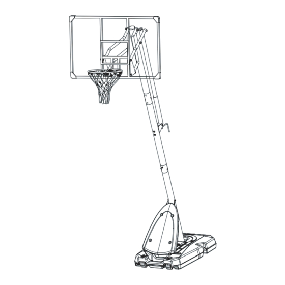
Portable basketball system
Hide thumbs
Also See for A61-045V00:
- Assembly instruction manual (46 pages) ,
- Assembly instruction manual (31 pages)

Related Manuals for SPORTNOW A61-045V00


Summary of Contents for SPORTNOW A61-045V00
- Page 1 IN230200407V01_DE_IT A61-045V00 Tragbarer Basketballkorb und Ständer WICHTIG - BITTE HEBEN SIE DIESE ANLEITUNG FÜR EINE SPÄTERE BEZUGNAHME AUF: SORGFÄLTIG DURCHLESEN MONTAGEANLEITUNG...
- Page 2 Sehr geehrter Kunde, Vielen Dank, dass Sie dieses Produkt erworben haben. Damit Ihr Gerät Ihnen gute Dienste leistet, lesen Sie bitte alle Hinweise in diesem Benutzerhandbuch. Wenn Sie Fragen haben, wenden Sie sich bitte an unser Kundendienstzentrum. Unsere Kontaktdaten stehen unten: Country Phone Email...
- Page 6 ① ② ③ ④ ⑤ ⑥ ⑦ ⑧ ⑨ 137*82*2.9mm ⑩ M8*65mm M10*40mm M8*40mm M8*90mm M12*160mm M8*95mm...
- Page 7 M8*85mm 5*25mm Φ12*φ16*18mm M12*160mm M8*25mm M6*45mm M12*55mm 25*12.5*1.0mm REQUIRED TOOLS 17*19mm 14*17mm 8*10mm...
- Page 8 SCHRITT 1 Befestigen Sie die untere Stange (1) wie abgebildet am Sockel (12). Befestigen Sie die untere Stange mit zwei Satz von Bolzen und Unterlegscheiben (16) und einer runden Platte (24). Benötigte Hardware Satz Bolzen, Unterlegscheiben M8 × 40 mm ANZAHL: 2 SCHRITT 2 Verwenden Sie vier Satz Bolzen, Unterlegscheiben und Muttern (34), um die Stützen (4) der unteren...
- Page 9 SCHRITT 3 Verwenden Sie einen Bolzen, eine Unterlegscheibe und eine Mutter (19), um die Stützen (4) der unteren Stange an der unteren Stange (1) zu befestigen. Benötigte Hardware Bolzen, Unterlegscheibe Mutter M8 x 95 mm ANZAHL: 1 M8*95mm SCHRITT 4 Stecken Sie die Achsen (#22) wie gezeigt in die Räder (#21).
- Page 10 SCHRITT 5 Verwenden Sie sechs Satz Bolzen, Unterlegscheiben und Muttern (35), um die Abdeckung (33) an der unteren Stange zu befestigen. Benötigte Hardware Bolzen, Unterlegscheibe Mutter M6 × 45 mm ANZAHL: 4 SCHRITT 6 Verwenden Sie zwei Satz Bolzen, Unterlegscheiben und Muttern (17), um die Befestigungsplatte (20) und die Platte (38) an der mittleren Stange (2) sicher zu befestigen.
- Page 11 SCHRITT 7 Verwenden Sie zwei Satz Bolzen, Unterlegscheiben und Muttern (25), um die mittlere Stange (2) an der unteren Stange (1) sicher zu befestigen. Benötigte Hardware Bolzen, Unterlegscheibe und Mutter M8 × 85 mm ANZAHL: 2 SCHRITT 8 Benötigte Hardware Satz Bolzen, Unterlegscheiben und Schrauben M8 ×...
- Page 12 SCHRITT 9 Verwenden Sie vier Satz Bolzen, Unterlegscheiben und Muttern (15), um zwei Anschlussplatten (13) der Rückwand (9) sicher zu befestigen. Benötigte Hardware Bolzen, Unterlegscheibe, Mutter M10 × 40 mm ANZAHL: 4 SCHRITT 10 a. Verwenden Sie zwei Satz Bolzen, Unterlegscheiben und Muttern (36), um zwei kurze Verbindungs- rohre (7) an den oberen Teilen der beiden Anschlussplatten (13) zu befestigen.
- Page 13 SCHRITT 11 Verwenden Sie zwei Satz Bolzen, Unterlegscheiben und Muttern (18), um die kurzen Verbindungsrohre (7) und die langen Verbindungsrohre (8) an der oberen Stange (3) zu befestigen. Benötigte Hardware Bolzen, Unterlegscheibe, Mutter M12 x 160 mm ANZAHL: 2 SCHRITT 12 a.
- Page 14 c. . Stecken Sie den Bolzen (31) in dieser Reihenfolge durch das lange Verbindungsrohr (8), eine Rohrunterlegscheibe (23), den oberen Griff (6), die andere Rohrunterlegscheibe (23) und das andere lange Verbindungsrohr (8) und ziehen Sie dann die Mutter fest. d. Verwenden Sie zwei Satz Bolzen, Unterlegscheiben und Muttern (25), um die obere Stange (3) an der mittleren Stange (2) sicher zu befestigen.
- Page 15 SCHRITT 14 Stellen Sie nach dem Zusammenbau sicher, dass alle Bolzen und Muttern fest angezogen sind. Prüfen Sie immer vor jeder Verwendung, ob der Sockel mit Wasser oder Sand gefüllt ist und ob alle Anbrin- gungen und Beschläge fest sitzen. WARNUNG Sand ist anstelle von Wasser zu empfehlen.
- Page 16 SCHRITT 16 Folgen Sie den nachfolgenden Bildern, um die Kurbel (32) zu drehen, damit Sie die Höhe einstellen können. Füllen Sie den gesamten Sockel mit Wasser -16-...
-
Page 17: Istruzioni Di Assemblaggio
IN230200407V01_DE_IT A61-045V00 Canestro da Basket Portatile IMPORTANTE - CONSERVARE QUESTE INFORMAZIONI PER CONSULTARLE IN SEGUITO: LEGGERE ATTENTAMENTE ISTRUZIONI DI ASSEMBLAGGIO -17-... - Page 18 Caro Cliente, Grazie per aver acquistato questo prodotto. Per servirti meglio con questo apparecchio ti prego di leggere tutte le istruzioni in presente manuale utente. In caso di dubbio, si prega di contattare il nostro centro assistenza clienti. I nostri dettagli di contatto sono di seguito: Country Telefono Email...
-
Page 19: Istruzioni Di Sicurezza
ISTRUZIONI DI SICUREZZA LA MANCATA OSSERVANZA DI QUESTE AVVERTENZE PU CAUSARE GRAVI LESIONI PERSONALI O DANNI ALLE PROPRIETÀ. Per garantire la sicurezza, non tentare di montare questo prodotto senza aver letto e senza seguire attentamente tutte le istruzioni. Controllare l'intera confezione e tutti i materiali di imballaggio per verificare le condizioni di parti e / o materiale di istruzioni aggiuntivo. - Page 20 AVVERTENZA LA MANCATA OSSERVANZA DI QUESTE AVVERTENZE PUO' CAUSARE GRAVI LESIONI E / O DANNI ALLA PROPRIETÀ. I PROPRIETARI DEVONO ASSICURARSI CHE TUTTI GLI UTENTI C O N O S C A N O E S E G U A N O Q U E S T E R E G O L E P E R U N FUNZIONAMENTO SICURO DEL PRODOTTO.
-
Page 21: Regolazione Dell'impianto
TRASPORTO DELLA BASE PORTATILE 1.Assicurarsi che la base sia vuota prima di trasportarla. 2. Tenersi rivolti verso la parte anteriore della base dove si trovano le ruote e tirare all'indietro il palo fino a quando l'unità è bilanciata sulle ruote. 3 . - Page 22 ① ② ③ ④ ⑤ ⑥ ⑦ ⑧ ⑨ 137*82*2.9mm ⑩ M8*65mm M10*40mm M8*40mm M8*90mm M12*160mm M8*95mm -22-...
- Page 23 M8*85mm 5*25mm Φ12*φ16*18mm M12*160mm M8*25mm M6*45mm M12*55mm 25*12.5*1.0mm REQUIRED TOOLS 17*19mm 14*17mm 8*10mm -23-...
- Page 24 PASSAGGIO 1 Fissare il palo inferiore (1) alla base (12) come illustrato. Fissare il palo inferiore con due set di bulloni e rondelle (16) e una piastra rotonda (24). Hardware Richiesto Set di Bullone e Rondella M8*40mm Qtà:2 PASSAGGIO 2 Utilizzare quattro set di bulloni, rondelle e dadi (34) per fissare i sostegni per il palo inferiore (4) alla base (12).
- Page 25 PASSAGGIO 3 Utilizzare un bullone, una rondella e un dado (19), fissare i sostegni per il palo inferiore (4) al palo inferiore (1). Hardware Richiesto Bullone, Rondella e Dado M8*95mm Qtà:1 M8*95mm PASSAGGIO 4 Inserire gli assi (#22) nelle ruote (#21) come mostrato, e poi premere sulle ruote per far scattare gli assi in posizione.
- Page 26 PASSAGGIO 5 Utilizzare sei set di bulloni, rondelle e dadi (35) per fissare il coperchio (33) al palo inferiore. Hardware Richiesto Bullone, Rondella e Dado M6*45mm Qtà:4 PASSAGGIO 6 Utilizzare due set di bulloni, rondelle e dadi (17) per fissare la piastra di montaggio (20) e la piastra (38) al palo centrale (2).
- Page 27 PASSAGGIO7 Utilizzare due set di bulloni, rondelle e dadi (25) per fissare il palo centrale (2) al palo inferiore (1). Hardware Richiesto Bullone, Rondella e Dado M8*85mm Qtà:2 PASSAGGIO8 Hardware Richiesto Set di Bullone, Rondella e Dado M8*60mm Qtà:2 Set di Bullone, Rondella e Dado M8*90mm Qtà:2 -27-...
- Page 28 PASSAGGIO 9 Utilizzare quattro set di bulloni, rondelle e dadi (15) per fissare due piastre di collegamento del tabel- lone (13) al tabellone (9). Hardware Richiesto Bullone, Rondella e Dado M10*40mm Qtà:4 PASSAGGIO 10 a. Utilizzare due set di bulloni, rondelle e dadi (36), fissare due tubi di collegamento corti (7) alle parti superiori delle due piastre di collegamento (13).
- Page 29 PASSAGGIO 11 Utilizzare due set di bulloni, rondelle e dadi (18) per fissare i tubi di collegamento corti (7) e lunghi (8) al palo superiore (3). Hardware Richiesto Bullone, Rondella e Dado M12*160mm Qtà:2 PASSAGGIO 12 a. Avvitare la barra di collegamento inferiore (5) alla barra di collegamento superiore (6). b.
- Page 30 c. Inserire il bullone (31) attraverso il tubo di collegamento lungo (8), una rondella per tubo (23), la barra di collegamento superiore (6), l'altro rondella per tubo (23) e l'altro tubo di collegamento lungo (8) in ordine per serrare il dado per bloccarli. d.Utilizzare due set di bulloni, rondelle e dadi (25) per fissare il palo superiore (3) al palo centrale (2).
- Page 31 PASSAGGIO 14 Una volta assemblata, assicurarsi che tutti i bulloni e i dadi siano serrati correttamente. Controllare sempre l’attrezzatura per verificare che la base sia piena d'acqua o di sabbia e che tutti i raccordi e la ferramenta siano serrati prima di ogni utilizzo. AVVERTENZA Si consiglia di utilizzare sabbia anziché...
- Page 32 PASSAGGIO 16 Seguire le figure sottostanti per ruotare la manovella (32), in modo da poter regolare l'altezza. Riempire l'intera base d'acqua -32-...
-
Page 33: Assembly Instruction
IN230200407V01_DE_IT A61-045V00 Portable Basketball System IMPORTANT, RETAIN FOR FUTURE REFERENCE: READ CAREFULLY ASSEMBLY INSTRUCTION -33-... - Page 34 Dear customer, Thank you for purchasing this product. So that your appliance serves you well, please read all the instructions in this user's manual. If you have any questions, please contact our customer care center. Our contact details are below: Country Phone Email...
-
Page 35: Safety Instructions
SAFETY INSTRUCTIONS FAILURE TO FOLLOW THESE WARNINGS MAY RESULT IN SERIOUS INJURY OR PROPERTY DAMAGE. To ensure safety, do not attempt to assemble this product without reading and following all instructions carefully. Check the entire box and inside all packing materials for parts and/or additional instruction material. Before beginning assembly, identify and inventory all parts and hardware using the parts and hardware lists and identifiers in this document. - Page 36 WARNING OWNERS MUST ENSURE THAT ALL PLAYERS KNOW AND FOLLOW THESE RULES FOR SAFE OPERATION OF THE SYSTEM. 1. Do Not allow children to move or adjust the system. 2. Always make sure adjustment knob is securely tightened before play. 3.
-
Page 37: Adjusting The System
TRANSPORTING THE PORTABLE BASE 1. Make sure the base is empty before moving. 2. Face the front of the base where the wheels are located and pull back on the pole until the unit is balanced on its wheels. 3. Move the unit to the desired location and carefully set it down. - Page 38 ① ② ③ ④ ⑤ ⑥ ⑦ ⑧ ⑨ 137*82*2.9mm ⑩ M8*65mm M10*40mm M8*40mm M8*90mm M12*160mm M8*95mm -38-...
- Page 39 M8*85mm 5*25mm Φ12*φ16*18mm M12*160mm M8*25mm M6*45mm M12*55mm 25*12.5*1.0mm REQUIRED TOOLS 17*19mm 14*17mm 8*10mm -39-...
- Page 40 STEP 1 Attach Bottom Pole (#1) to Base(#12) as shown. Secure the bottom pole to the base with 2 sets of Bolts and Washers (#16) and round plate (#24) as shown. STEP 2 Lock the Bottom Pole Braces (#4) to Base (#12) with 4 sets of Bolts, Washers, and Nuts (#34). -40-...
- Page 41 STEP 3 Attach the Bottom Pole Braces (#4) to Bottom pole (#1) with a set of Bolt, Washer and Nut (#19). M8*95mm STEP 4 Insert Axles (#22) into the Wheels (#21) as shown. Then press down over the wheels to snap the Axles in place.
- Page 42 STEP 5 Secure Cover (#33) to Bottom Pole Braces (#4) using 6 sets of Bolts, Washers and Nuts (#35). STEP 6 Secure Mounting Plate (#20) and Plate (#38) to Middle Pole (#2) with 2 sets of Bolts, Washers, and Nuts (#17) . -42-...
- Page 43 STEP 7 Secure Middle Pole (#2) to Bottom Pole (#1) with 2 sets of Bolts, Washers, and Nuts (#25). STEP 8 -43-...
- Page 44 STEP 9 Secure two Backboard Connecting Plates (#13) to Backboard (#9) with 4 sets of Bolts, Washers, and Nuts (#15). STEP 10 a. Attach two Short Connecting Tubes (#7) to Upper Parts of two Backboard Connecting Plates (#13) with 2 sets of Bolts, Washers, and Nuts (#36). b.
- Page 45 STEP 11 Attach Short Connecting Tubes (#7) and Long Connecting Tubes (#8) to the Top Pole (#3) as shown. Secure them with 2 sets of Bolts, Washers, and Nuts (#18). STEP 12 a. Screw the Lower Handle Bar (#5) to the Upper Handle Bar (#6). b.
- Page 46 c. Insert the Bolt (#31) through a Long Connecting Tube (#8), a Tube Washer (#23), the Upper Handle Bar (#6), the other Tube Washer (#23) and the other Long Connecting Tube (#8) order. Then tighten the nut to lock them. d.
- Page 47 STEP 14 Please check all the bolts and nuts are all tightened after assembly. Always check the unit to ensure that the base is full of water or sand, and all ings and hardware are tight before each use. WARNING Sand is more recommended instead of water.
- Page 48 STEP 16 Please follow the below pictures to rotate the Crank Handle (#32) to adjust height. -48-...
Need help?
Do you have a question about the A61-045V00 and is the answer not in the manual?
Questions and answers