SPORTNOW A61-045V00 Assembly Instruction Manual
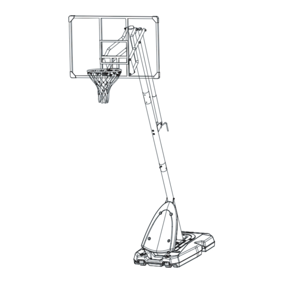
Portable basketball system
Hide thumbs
Also See for A61-045V00:
- Assembly instruction manual (46 pages) ,
- Assembly instruction manual (48 pages)

Subscribe to Our Youtube Channel
Related Manuals for SPORTNOW A61-045V00


Summary of Contents for SPORTNOW A61-045V00
- Page 1 IN230200407V01_FR A61-045V00 Panier de basket-ball sur pied IMPORTANT - CONSERVEZ CES INFORMATIONS POUR VOTRE CONSULTATION ULTÉRIEURE: LISEZ ATTENTIVEMENT INSTRUCTIONS D'ASSEMBLAGE...
- Page 5 137*82*2.9mm M8*65mm M10*40mm M8*40mm M8*90mm M12*160mm M8*95mm...
-
Page 6: Required Tools
M8*85mm 5*25mm 12* 16*18mm M12*160mm M8*25mm M6*45mm M12*55mm 25*12.5*1.0mm REQUIRED TOOLS 17*19mm 14*17mm 8*10mm... - Page 7 ÉTAPE 1 Fixez le Poteau Inférieur (#1) à la Base (#12) comme indiqué. Fixez le poteau inférieur à la base à l'aide de 2 ensembles de Boulons et de Rondelles (#16) ainsi que de la plaque ronde (#24) comme illustré. Matériel nécessaire Ensemble boulon, rondelle M8*40mm...
- Page 8 ÉTAPE 3 Fixez les Renforts de Poteau Inférieur (#4) au Poteau Inférieur (#1) avec un ensemble de boulon, rondelle et écrou (#19). Matériel nécessaire Boulon, rondelle, écrou M8*95mm M8*95mm Qté:1 ÉTAPE 4 Insérez les Essieux (#22) dans les Roues (#21) comme indiqué. Appuyez ensuite sur les roues pour emboîter les Essieux en place.
- Page 9 ÉTAPE 5 Fixez le Couvercle (#33) aux Supports du Poteau Inférieur (#4) en utilisant 6 ensembles de Bou- lons, Rondelles et Écrous (#35). Matériel nécessaire Boulon, rondelle, écrou M6*45mm Qté:4 ÉTAPE 6 Fixez la Plaque de Montage (#20) et la Plaque (#38) au Poteau Central (#2) avec 2 ensembles de boulons, rondelles et écrous (#17).
- Page 10 ÉTAPE 7 Fixez le Poteau Central (#2) au Poteau Inférieur (#1) avec 2 ensembles de boulons, rondelles et écrous (#25). Matériel nécessaire Boulon, rondelle and écrou M8*85mm Qté:2 ÉTAPE 8 Matériel nécessaire Boulon, rondelle and écrou M8*85mm Qté:2 Ensemble boulon, rondelle et vis M8*90mm Qté:2...
- Page 11 ÉTAPE 9 Fixez deux Plaques de Raccordement (#13) au Panneau Arrière (#9) avec 4 ensembles de bou- lons, rondelles et écrous (#15). Matériel nécessaire Boulon, rondelle, écrou M10*40mm Qté:4 ÉTAPE 10 a.Attachez deux Tubes de Raccordement Courts (#7) aux Parties Supérieures des deux Plaques de Raccordement (#13) avec 2 ensembles de boulons, rondelles et écrous (#36).
- Page 12 ÉTAPE 11 Attachez les Tubes de Raccordement Courts (#7) et les Tubes de Raccordement Longs (#8) au Poteau Supérieur (#3) comme indiqué. Fixez-les avec 2 ensembles de boulons, rondelles et écrous (#18). Matériel nécessaire Boulon, rondelle, écrou M12*160mm Qté:2 ÉTAPE 12 a.Vissez la Barre de Poignée Inférieure (#5) à...
- Page 13 c. Insérez le boulon (#31) à travers un Tube de Raccordement Long (#8), une Rondelle de Tube (#23), la Barre de Poignée Supérieure (#6), l'autre Rondelle de Tube (#23) et l'autre Tube de Raccordement Long (#8) dans l'ordre. Serrez ensuite l'écrou pour les verrouiller. d.
- Page 14 ÉTAPE 14 Vérifiez que tous les boulons et écrous sont bien serrés après l'assemblage. Assurez-vous toujo- urs que la base est remplie d'eau ou de sable et que toutes les pièces et quincailleries sont bien fixées avant chaque utilisation. AVERTISSEMENT Le sable est préférable à...
- Page 15 ÉTAPE 16 Suivez les images ci-dessous pour tourner le levier de manivelle (#32) afin d'ajuster la hauteur. Remplissez entièrement la Base avec de l'eau.
-
Page 16: Assembly Instruction
IN230200407V01_EN A61-045V00 Portable Basketball System IMPORTANT, RETAIN FOR FUTURE REFERENCE: READ CAREFULLY ASSEMBLY INSTRUCTION... - Page 20 137*82*2.9mm M8*65mm M10*40mm M8*40mm M8*90mm M12*160mm M8*95mm...
- Page 21 M8*85mm 5*25mm 12* 16*18mm M12*160mm M8*25mm M6*45mm M12*55mm 25*12.5*1.0mm REQUIRED TOOLS 17*19mm 14*17mm 8*10mm...
- Page 22 STEP 1 Attach Bottom Pole (#1) to Base(#12) as shown. Secure the bottom pole to the base with 2 sets of Bolts and Washers (#16) and round plate (#24) as shown. STEP 2 Lock the Bottom Pole Braces (#4) to Base (#12) with 4 sets of Bolts, Washers, and Nuts (#34).
- Page 23 STEP 3 Attach the Bottom Pole Braces (#4) to Bottom pole (#1) with a set of Bolt, Washer and Nut (#19). M8*95mm STEP 4 Insert Axles (#22) into the Wheels (#21) as shown. Then press down over the wheels to snap the Axles in place.
- Page 24 STEP 5 Secure Cover (#33) to Bottom Pole Braces (#4) using 6 sets of Bolts, Washers and Nuts (#35). STEP 6 Secure Mounting Plate (#20) and Plate (#38) to Middle Pole (#2) with 2 sets of Bolts, Washers, and Nuts (#17) .
- Page 25 STEP 7 Secure Middle Pole (#2) to Bottom Pole (#1) with 2 sets of Bolts, Washers, and Nuts (#25). STEP 8...
- Page 26 STEP 9 Secure two Backboard Connecting Plates (#13) to Backboard (#9) with 4 sets of Bolts, Washers, and Nuts (#15). STEP 10 a. Attach two Short Connecting Tubes (#7) to Upper Parts of two Backboard Connecting Plates (#13) with 2 sets of Bolts, Washers, and Nuts (#36). b.
- Page 27 STEP 11 Attach Short Connecting Tubes (#7) and Long Connecting Tubes (#8) to the Top Pole (#3) as shown. Secure them with 2 sets of Bolts, Washers, and Nuts (#18). STEP 12 a. Screw the Lower Handle Bar (#5) to the Upper Handle Bar (#6). b.
- Page 28 c. Insert the Bolt (#31) through a Long Connecting Tube (#8), a Tube Washer (#23), the Upper Handle Bar (#6), the other Tube Washer (#23) and the other Long Connecting Tube (#8) order. Then tighten the nut to lock them. d.
- Page 29 STEP 14 Please check all the bolts and nuts are all tightened after assembly. Always check the unit to ensure that the base is full of water or sand, and all ings and hardware are tight before each use. WARNING Sand is more recommended instead of water.
- Page 30 STEP 16 Please follow the below pictures to rotate the Crank Handle (#32) to adjust height.
Need help?
Do you have a question about the A61-045V00 and is the answer not in the manual?
Questions and answers