Table of Contents
Advertisement
Quick Links
Advertisement
Table of Contents

Related Manuals for Juniper Mist Edge ME-X6


Summary of Contents for Juniper Mist Edge ME-X6
- Page 1 Juniper Mist Edge ME-X6 Hardware Guide Published 2024-10-30...
- Page 2 The Juniper Networks product that is the subject of this technical documentation consists of (or is intended for use with) Juniper Networks software. Use of such software is subject to the terms and conditions of the End User License Agreement ("EULA") posted at https:/ /support.juniper.net/support/eula/.
-
Page 3: Table Of Contents
Table of Contents About This Guide | v Overview ME-X6 Overview | 2 ME-X6 Chassis | 3 ME-X6 Specifications | 14 Installation Unpack the ME-X6 | 18 Mount the ME-X6 | 19 Attach the Mounting Rails to a Four-Post Rack | 20 Attach the Mounting Rails to a Two-Post Rack (Center Mount) | 23 Attach the Mounting Rails to a Two-Post Rack (Flush Mount) | 26 Attach the Device to the Mounting Rails | 29... - Page 4 Contact Support Contact Customer Support and Return the Chassis or Components | 50 Contact Customer Support | 50 Return a Hardware Component to Juniper Networks | 51 Request a Return Material Authorization | 51 Locate the Serial Number | 52...
-
Page 5: About This Guide
About This Guide Use this guide to install and troubleshoot the Juniper Mist™ Edge ME-X6. After completing the installation procedures covered in this guide, refer to the Juniper Mist™ Edge documentation for information about further configuration. -
Page 6: Overview
PART Overview ME-X6 Overview | 2 ME-X6 Chassis | 3 ME-X6 Specifications | 14... -
Page 7: Me-X6 Overview
Juniper Mist cloud and Marvis AI to analyze localized data. The Juniper Mist Edge ME-X6 provides a centralized datapath for user traffic, a task that legacy wireless controllers traditionally performed. It enables on-premise tunnel termination of traffic to and from access points. -
Page 8: Me-X6 Chassis
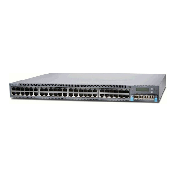
• Tunneled WLANs and flexible traffic redirection—The Juniper Mist microservices architecture provides the flexibility to form multiple tunnels to different Juniper Mist Edge appliances to meet the wireless configuration requirements. A Juniper Mist Edge deployment can support both locally bridged and tunneled WLANs. - Page 9 Figure 2: ME-X6 Front Panel Table 1: Components on the ME-X6 Front Panel Callout Component Description Status LED control panel Indicates component and system status Storage drives Used for data storage Power button Used to manually power on or off the system USB port USB 2.0 port used to connect USB...
-
Page 10: Status Leds On The Me-X6
Status LEDs on the ME-X6 The status LED control panel is located at the front of the device. You can see the status LEDs without removing the front bezel. Figure 3: ME-X6 Status LED Control Panel... - Page 11 Table 2: Components on the ME-X6 Status LED Control Panel Callout Component Color Description Drive indicator Solid amber The system has detected a drive error. • Check the system event logs. • Run the appropriate Online Diagnostics test. Restart the system and run embedded diagnostics.
- Page 12 (Continued) Table 2: Components on the ME-X6 Status LED Control Panel Callout Component Color Description Electrical indicator Solid amber The system has detected an electrical error. • Check the system event logs. • Check the LED indicator on the PSU. You may need to reseat the PSU.
-
Page 13: Storage Drive Leds
(Continued) Table 2: Components on the ME-X6 Status LED Control Panel Callout Component Color Description Blinking blue The system ID mode is active. NOTE: Press the system health and system ID button to switch between system ID mode and sytem health mode. Solid amber The system is in fail-safe mode. -
Page 14: Me-X6 Rear Panel
(Continued) Table 3: Storage Drive LEDs Color Description Blinking green slowly The drive is rebuilding. Blinking green, amber, and then off There is an unexpected drive failure. Blinking green for three seconds, The drive rebuild has stopped. amber for three seconds, and then Blinking amber The drive has failed. - Page 15 (Continued) Table 4: Components on the ME-X6 Rear Panel Callout Component Description iDRAC dedicated port Used to remotely access iDRAC 3 and 5 Data ports Four 25-GbE SFP28 ports. They act as the endpoint for tunnels from the APs. Power supplies Two 800 W AC power supplies USB 2.0 port USB 2.0 port used to connect USB...
-
Page 16: Data Port Leds
Data Port LEDs Table 5: Data Port LEDs Link LED indicator Activity LED indicator Description Port is not connected to the network. Solid green Blinking green Port is connected to the network at maximum port speed and there is link activity. Port is connected to the network at maximum port speed and there is no link activity. -
Page 17: Power Supply Leds
(Continued) Table 6: Management Port LEDs Link LED indicator Activity LED indicator Description Solid green Blinking green Port is connected to the network at maximum port speed and there is link activity. Port is connected to the network at maximum port speed and there is no link activity. - Page 18 (Continued) Table 7: Power Supply LED LED color Description Blinking green and then off This is seen when plugging in a power supply while the system is running. It indicates a power supply mismatch due to efficiency, feature set, health status, or supported voltage.
-
Page 19: Me-X6 Specifications
ME-X6 Specifications Figure 5: ME-X6 Dimensions Table 8: ME-X6 Physical Specifications Parameter Value Form Factor Height 1.68 in. (4.3 cm) Width 19 in. (48.2 cm) Depth 18.8 in. (47.8 cm) - Page 20 (Continued) Table 8: ME-X6 Physical Specifications Parameter Value Weight 29.9 lb (13.6 kg) Power supplies Dual, hot-plug, redundant, 800 W Cooling system Multiple internal fans Table 9: ME-X6 Network Capacity Parameter Value Maximum APs 5000 Maximum clients 100,000 Maximum throughput 100 Gbps Data interfaces Quad-port 25GbE SFP28...
- Page 21 (Continued) Table 10: ME-X6 Power Specifications Parameter Value Idle power draw 105 W Maximum heat dissipation 3139 BTU/hour Table 11: ME-X6 Environmental Specifications Parameter Value Operating temperature 23 °F through 131 °F (-5 °C through 55 °C) Ambient temperature restriction 131 °F (55 °C) Mean time between failures (MTBF) 231,000 hours...
-
Page 22: Installation
PART Installation Unpack the ME-X6 | 18 Mount the ME-X6 | 19 Initial Setup for Mist Edge Devices | 33... -
Page 23: Unpack The Me-X6
Unpack the ME-X6 We ship the ME-X6 inside a cardboard carton. The ME-X6 has maximum protection inside the carton. Do not unpack it until you are ready to begin installation. To unpack the ME-X6: 1. Move the cardboard carton to a staging area as close to the installation site as possible. Make sure that you have enough room to remove the components from the chassis. -
Page 24: Mount The Me-X6
Mount the ME-X6 IN THIS SECTION SUMMARY Attach the Mounting Rails to a Four-Post This topic guides you through the steps to mount Rack | 20 your device on a two-post or four-post rack. Attach the Mounting Rails to a Two-Post Rack (Center Mount) | 23 Attach the Mounting Rails to a Two-Post Rack (Flush Mount) | 26... -
Page 25: Attach The Mounting Rails To A Four-Post Rack
Figure 6: Rack Mounting Kit Components Attach the Mounting Rails to a Four-Post Rack To attach the mounting rails to a four-post rack: 1. Open the latch on the rear rail of the mounting rail assembly. Align the guide blocks on the rear rail with the rear-post holes. - Page 26 Figure 7: Attach the Rear Mounting Rail 2. Open the latch on the front rail of the mounting rail assembly. Pull the front rail towards the front of the rack so that the guide blocks slot into the front-post holes.
- Page 27 Figure 8: Attach the Front Mounting Rail 3. Use the supplied screws to secure the mounting rails to the rack posts. Lock the front latch in place. Use the conical washers in case of a rack with square holes.
-
Page 28: Attach The Mounting Rails To A Two-Post Rack (Center Mount)
Figure 9: Secure the Mounting Rails 4. Repeat the process for the other mounting rail assembly. Attach the Mounting Rails to a Two-Post Rack (Center Mount) To attach the mounting rails to a two-post rack for a center mount: 1. Pull the latch on the mounting rail assembly and slide out the rear mounting rail. - Page 29 Figure 10: Remove the Rear Mounting Rail 2. Slide the two L-brackets on to the front mounting rail assembly. Make sure that the flanges of the L- brackets face each other. Figure 11: Attach the L-Brackets 3. Secure the front L-bracket to the mounting rail assembly by using the provided screws.
- Page 30 Figure 12: Secure the Front L-Bracket 4. Attach the front and rear L-brackets to the rack post by using the provided screws and washers. Figure 13: Attach the L-Brackets to the Rack 5. Secure the rear L-bracket to the mounting rail assembly by using the provided screws.
-
Page 31: Attach The Mounting Rails To A Two-Post Rack (Flush Mount)
Figure 14: Secure the Rear L-Bracket 6. Repeat the process for the other mounting rail assembly. Attach the Mounting Rails to a Two-Post Rack (Flush Mount) To attach the mounting rails to a two-post rack for a flush mount: 1. Pull the latch on the mounting rail assembly and slide out the rear mounting rail. - Page 32 Figure 15: Remove the Rear Mounting Rail 2. Slide the L-bracket on the mounting rail assembly so that the flange faces the front of the rack. Figure 16: Attach the L-Bracket 3. Open the latch on the front rail of the mounting rail assembly. Pull the front rail towards the front of the rack so that the guide blocks slot into the front-post holes.
- Page 33 Figure 17: Attach the Front Mounting Rail 4. Secure the L-bracket to the rack post by using the provided screws and washers. Figure 18: Attach the L-Bracket to the Rack Post...
-
Page 34: Attach The Device To The Mounting Rails
5. Secure the L-bracket to the mounting rail assembly by using the provided screws. Figure 19: Attach the L-Bracket to the Mounting Rail Assembly Attach the Device to the Mounting Rails Ensure that you have securely installed the mounting rails on the rack. To install the front bezel on the device, see "Install the Front Bezel and Bezel Filter"... - Page 35 Figure 20: Remove the Mounting Brackets 2. Align the holes on the mounting bracket with the shoulder screws on the side of the device. Attach the mounting bracket by sliding it towards the rear of the device. Secure the mounting bracket to the device by using the provided screws.
- Page 36 Figure 21: Attach the Mounting Brackets to the Device 3. Lift the device and position it so that the side mounting brackets are aligned with the mounting rails. Slide the device into the channels of the mounting rails.
- Page 37 Figure 22: Slide the Device into the Mounting Rails 4. Tighten the screws on the front flanges of the device to secure it to the rack.
-
Page 38: Initial Setup For Mist Edge Devices
Figure 23: Secure the Device Initial Setup for Mist Edge Devices IN THIS SECTION Claim a Mist Edge Device | 34 Configure the OOBM Port | 36 Configure the Tunnel Ports | 37 To set up your Mist Edge device: 1. -
Page 39: Claim A Mist Edge Device
5. Connect the tunnel (data) ports on the rear panel of the device to the network. "Configure the Tunnel Ports" on page 37 for the configuration. For the detailed configuration and deployment procedures, see the Juniper Mist Edge Guide. Claim a Mist Edge Device IN THIS SECTION... - Page 40 6. Select Device Inventory. You'll see the new Mist Edge listed under the Unassigned group in the Mist Edges tab. Claim a Mist Edge Using the Mist Portal 1. Log in to your account at https:/ /manage.mist.com/. 2. Navigate to Mist Edges and click on Claim Mist Edge. 3.
-
Page 41: Configure The Oobm Port
By default, the OOBM port is configured for Dynamic Host Configuration Protocol (DHCP). 3. If your network is not DHCP enabled, use the Juniper Mist Edge CLI to configure the OOBM port. Use the Integrated Dell Remote Access Controller (iDRAC) port to access the CLI. -
Page 42: Configure The Tunnel Ports
The Dashboard comes up. b. Click the Virtual Console on the bottom-left side of the window and log in. The username is mist and the password is the claim code of the device. The claim code is located above the QR code on the pull-out tab. c. - Page 43 Upstream Port VLAN ID is optional and should only be used whenever the upstream switchport is configured as an access port with a single untagged VLAN. 4. To create a single-arm configuration, in the Juniper Mist portal, clear the Separate Upstream and Downstream Traffic option. you can assign the interfaces as needed.
-
Page 45: Maintaining Components
PART Maintaining Components Replace the Front Bezel and Bezel Filter | 41 Reseat the Storage Drive | 43 Reseat the Power Supply | 47... -
Page 46: Replace The Front Bezel And Bezel Filter
Replace the Front Bezel and Bezel Filter IN THIS SECTION Remove the Front Bezel and Bezel Filter | 41 Install the Front Bezel and Bezel Filter | 42 Remove the Front Bezel and Bezel Filter To remove the front bezel and bezel filter: 1. -
Page 47: Install The Front Bezel And Bezel Filter
Install the Front Bezel and Bezel Filter To install the front bezel and bezel filter: 1. Place the filter in the bezel cavity under the filter bracket. Ensure that the filter is smooth and aligned with the slot. 2. Align the filter bracket with the guides on the bezel. Ensure that the painted surface of the filter faces the bezel. -
Page 48: Reseat The Storage Drive
4. Align the front bezel with the holes on the left and right flanges of the system. 5. Tighten the screws to secure the bezel. Reseat the Storage Drive IN THIS SECTION Remove a Storage Drive | 43 Install a Storage Drive | 45 The storage drives on the ME-X6 are not field-replaceable components. - Page 49 1. Prepare the drive for removal using the management software. Ensure that the drive indicators are off before removing the drive. 2. Press the release button to open the drive carrier release handle. 3. Hold the drive carrier release handle and slide the drive carrier out of the slot. 4.
-
Page 50: Install A Storage Drive
Install a Storage Drive Remove the front bezel to access the storage drives. To install the drive carrier and storage drive: 1. Insert the drive into the drive carrier with the drive connector facing towards the rear of the carrier. - Page 51 2. Align the screw holes on the drive with the screw holes on the drive carrier. Using a screwdriver, secure the drive to the drive carrier with the screws. 3. Slide the drive carrier into the drive slot. 4. Close the drive carrier release handle to lock the drive in place.
-
Page 52: Reseat The Power Supply
Reseat the Power Supply IN THIS SECTION Remove a Power Supply | 47 Install a Power Supply | 48 The power supplies on the ME-X6 are not field-replaceable components. If the power supply on your device needs to be replaced, follow the RMA procedure. Remove a Power Supply To remove a power supply: 1. -
Page 53: Install A Power Supply
Install a Power Supply If your device has redundant power supplies, make sure that they are of the same type and have the same maximum output power. To install a power supply: 1. Hold the power supply handle and slide the power supply into the slot on the device. The release latch snaps into place. -
Page 54: Contact Support
PART Contact Support Contact Customer Support and Return the Chassis or Components | 50... -
Page 55: Contact Customer Support And Return The Chassis Or Components
IN THIS SECTION SUMMARY Contact Customer Support | 50 If you need to return a hardware component to Juniper Networks, Inc., you need a Return Material Return a Hardware Component to Juniper Authorization (RMA) number and the equipment Networks | 51 serial number. -
Page 56: Return A Hardware Component To Juniper Networks
Return a Hardware Component to Juniper Networks If a hardware component fails, contact Juniper Networks to obtain an RMA number. We use this number to track the returned material at the factory and to return the repaired or new components to you, as needed. -
Page 57: Locate The Serial Number
• Type of activity you were performing on the device when the problem occurred • Configuration data displayed by one or more show commands You can contact JTAC using the Support page or by telephone. If you're contacting JTAC by telephone: •... - Page 58 • Place the individual components in antistatic bags. • Write the RMA number on the exterior of the box to ensure proper tracking. NOTE: Remove the power supply units (PSUs) before packing the device. CAUTION: Avoid stacking any of the hardware components.
-
Page 59: Agency Approvals
PART Agency Approvals ME-X6 Agency Approvals | 55... -
Page 60: Me-X6 Agency Approvals
ME-X6 Agency Approvals The ME-X6 complies with the following standards: • Safety • IEC 60950-1:2005 ed2 +A1:2009 +A2:2013 • EN 62479:2010 • EN 62368-1:2014 +A11:2017 • EN IEC 62368-1:2020 +A11:2020 • EN 62311:2008 • EN IEC 62311:2020 • EMC • EN 55032:2015 +A11:2020 •...
Need help?
Do you have a question about the Mist Edge ME-X6 and is the answer not in the manual?
Questions and answers