jablotron 100+, JI-113C, JI-114C-A Manual
- User manual ,
- Manual (26 pages) ,
- Manual (5 pages)
Advertisement
Product Function

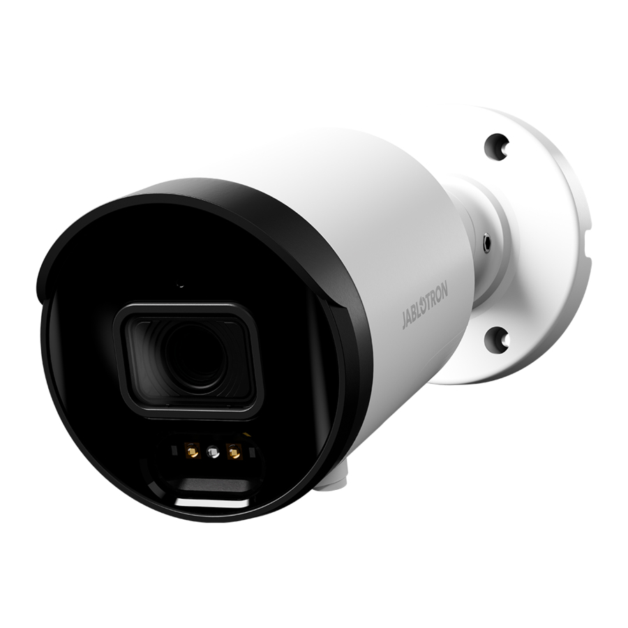
Fig. 1: Description of the outer parts of the product
See Fig. 1
- Rotating ring of the camera;
- IR emitter;
- Camera lens;
- Bayonet cap;

Fig. 2: How the JABLOTRON CLOUD works
See Fig. 2
The camera is fully preconfigured so that it can immediately use the following MyJABLOTRON services:
- Live streaming
- Recording history - Video recordings are stored on the server for a limited time (depending on the type of service).
- Video sequence (video clip) – a 1-minute recording consisting of 30 seconds before and 30 seconds after the event (in the case of a paid service, 5 minutes of recording, i.e. 30 seconds before and 4.5 minutes after the event). The recording is associated with a configurable alarm system event (alarm, setting, shutdown from a selected section). The PG control can also be set for the paid service. The maximum number of video sequences is limited depending on the selected type of service.
- Connection to ARC - access to the video data of the camera is granted to a security agency for visual verification of an alarm event.
Installation
The camera may be powered over LAN using PoE. Alternatively, the camera may be powered with a 12V DC, 0.5 A power supply, and must be connected to LAN with a RJ-45 terminated cable. A waterproof LAN housing is included in the packaging, which must be used to prevent moisture from potentially damaging the data connector. To prevent moisture from potentially damaging the data connector, a waterproof LAN connector housing must be used (which is included in the packaging).
Installation procedure using the mounting socket
If the camera is to be mounted on a surface which does not allow the cables and connectors to be securely hidden, it is recommended to use the included mounting socket (included in the camera packaging) which covers the cables. See Figure 3 for installation diagram.

Fig. 3: Installation procedure using the mounting socket
- cable seal;
- waterproof connector cover;
- blanking plug;
- side hole for cable passage;
- O-ring;
- power connector;
- LAN connector;
- mounting socket cover;
- cable seal;
- camera mount;
- Select the location of the camera, consider the wiring and the best view of the area to be monitored.
- Use the self-adhesive template to mark the mounting holes of the mounting socket.
- Drill holes in the selected location with a Ø 6mm drill bit and fix with dowels from the package. Open the mounting base by removing the screws. Depending on the selected cable feed method – centre or side (8), prepare a hole for running the cables. In case of side installation use the cable grommet (4, 5, 6) for the selected hole – (the cable grommet is included in the packing), use the blanking plug (7) for the unused one.
- Pull the LAN cable through the back of the socket. Screw the back of the socket onto the selected place on the wall with the three screws provided in the packaging. crimp the RJ-45 connector with crimping pliers (see Fig. 4).

- camera connector;
- O-ring;
- connector;
- waterproof cover;
- cable seal;
- bayonet cap;
- internet cable;
- Plug the RJ-45 connector to LAN connector. If the utilized router or switch does not provide PoE (power over Ethernet), connect the camera power (9) connector to an external 12 V DC power supply (min. 0.5 A).
- Release the camera mount (14) by turning the rotating ring (1) counter-clockwise when facing the back of the camera. Screw the lid of the mounting socket onto the bottom of the socket and screw the camera mount to the mounting socket using the three screws included in the packaging.
- Adjust the camera to the selected position and place it on the camera mount screwed onto the lid of the mounting socket, secure the camera in place by turning the ring clockwise.
- Register the camera to MyCOMPANY to access the camera preview and adjust the camera view as required using the screws on the camera.
- Remove the protective film and polish the camera of any dirt and fingerprint marks, should be any present.

Installation procedure for the unit without using the mounting socket
If the camera is to be installed on a support that can be used to protect the cables and connectors from intentional damage (e.g., lowered ceiling, plasterboard ceilings and partitions, etc.), the camera can be installed directly on such a support and the cables and connectors can be pushed through the prepared hole. See Figure 4.
Note: The waterproof cover must be istalled on the cable before the RJ-45 data connector is crimped on.
Power
The camera must be powered at all times, the camera may be powered in two ways:
- Power via PoE (Power over Ethernet), if the network connection point does not support this feature, a PoE power module may be utilized. The voltage (48) is standardized by the IEEE 802.3af standard. The advantage is that the camera is powered directly via the data cable.
- An external 12 V/0.5 A power supply equipped with a 2.1 mm connector. This method requires a second cable for power as well as a data cable. The advantage is that the camera may be backed up with a backup power supply unit.
Data transfer and communication with the server
The ports on which the camera communicates to the cloud are 8900, 8901. For normally configured networks it is not necessary to enable anything in the router or firewall.
Note: The camera is not physically connected to the JABLOTRON 100 system, it doesn´t occupy any position. Power from the alarm system is not required and the camera status is not monitored by the system.
Registration to a server
Registration can be performed from the web or a smart application MyCOMPANY for cell phones by entering the unique camera MAC address on the label stuck on camera body or on its box. It can also be scanned by QR code. Every camera can be registered to only one JALOTRON 100 system. There is a 20-minute time-out after power is connected when the camera can be registered. When this time frame expires then registration can be repeated by voltage restart.
Registration procedure:
- Connect the power to the camera (initialisation takes approx. 1 minute).
- Log in to the MyCOMPANY application and the INSTALLATION LIST will open.
- Select the installation to which you want to register the camera.
- Go to the CAMERAS tab (in down menu) and click onto REGISTER A CAMERA.
- Scan QR with MAC address of the camera, SEARCH cameras and write the name which will be displayed in MyJABLOTRON and click onto REGISTER.
- When registration is confirmed in MyCOMPANY, in the following 24 hours the installer can watch a live preview from this camera. However, this parameter can be extended or shortened in MyJABLOTRON. Permanent livestreaming is available in the MyJABLOTRON application for the end user.

Because of security reasons it is impossible to record data to another storage system (like local NVR etc.). Access to the camera's internal settings is blocked.
MyCOMPANY programmable options
Settings of camera configuration is possible by clicking on chosen camera.
Camera configuration – following parameters are to be set:
Camera name – filled camera name will be displayed in MyCOMPANY and MyJABLOTRON.
Picture quality: 1 MPx, 2MPx, 3 MPx, 4MPx, 5MPx
Selecting one of the available options allows you to modify the image quality and data bitrate.
Video retention period (record export to MyJABLOTRON): 3 days / 7 days / 15 days / 30 days
Depending on the subscription service, 10 or 60 clips are available. The recordings are deleted either after the set period of time or when the number of clips is exhausted. Only after this selected retention period, it is also possible to request the export of video clips.
Activation of video clips for sections: for each camera can choose according to options – Alarm / Arm / Disarm state.
If the check button is set to ON for selected section, it means that video sequences will be saved for those sections and events. The number of sections is according to the set configuration and in each section, there are 3 events for which video sequences can be saved. The camera saves the recording 30 seconds before and 30 seconds after the event, up to 4.5 minutes after the event for the paid service.
Activation on PG event – for each PG can choose according to options – Activation/Deactivation (by check button).
Advanced settings
- Camera image masking – The camera does not save or display the area where the mask is – the blackened area. In MyCOMPANY is available preview and option +Add mask.
- IP address – 2 options
- Dynamic address – network settings are taken over from the DHCP router
- Static address – possibility to insert your own IP address
- Setting the day and night mode:
- Automatic – switches between modes based on lighting conditions
- Day mode – daytime only (color recording), does not turn on IR LED at night Night mode – continuous black and white
- recording
WDR – check button ON/OFF
It should be enabled when the camera is scanning an area where there are rapid changes in contrast.
Show the name of the camera in the image: check button ON*/OFF
Connect to ARC – this option sends a request for connection to a monitoring agency ARC.
Deactivate the camera – Button to unregister the camera including all records from the server. It is not possible to unregister a camera on which the PCO service is active. If the camera is unregistered in a disconnected state, the camera will not be unregistered correctly and the manual reset is required. The manual reset button is located on the underside of the camera under the cover, which is secured with two screws. After unscrewing the cover, it is necessary to hold the button, connect the power and hold the button for about 15 seconds.
Recommendations
In the case of connecting more cameras to the system, it is necessary to take into account a larger data flow and therefore to ensure a separate data flow for each camera in the upload direction.

The manufacturer strictly warns users that due to the camera's ability to acquire video recordings, the camera has to be used within limits as determined by national laws and regulations, especially laws concerning the protection of privacy and personal data.
According to these regulations, users have an obligation to obtain the approval of people in range of the camera, or the obligation to indicate the image capture area by informative signs.
The manufacturer recommends that users should be aware of the legal obligations applicable to the operation of CCTV before installation and use of the camera.
Technical parameters
| Power supply | from PoE (48V) data connection (according to IEE 802.3af) alternatively via 12 V DC power connector |
| Quiescent current consumption | 250 mA |
| Maximum current draw | 458 mA |
| Number of pixels | 5 Mpix |
| Camera resolution and bitrate | 1-5 MPX, 448-3072 kbps (according setting in app) |
| FPS | 15 |
| Lens | 3.6 mm (91° angle of view) |
| Lens type | M12 plate lens |
| Sensing chip | 1/2.7' Progressive CMOS |
| WDR – half-light compensation | Yes |
| Camera setup options | horizontal: 91°, vertical: 46° |
| Communication interface | LAN |
| IR illumination range | 30 m |
| Environment | outdoor general |
| Operating temperature range | -35°C to +60°C |
| Average operating humidity | up to 75% non-condensing |
| Degree of protection | IP67 |
| Dimensions | ø 100 x 90 mm |
| Camera weight | 418 g |
| Weight of socket | 317 g |
| In compliance with | EN 55032, EN 50130-4, EN IEC 63000 |
Documents / Resources
References
Download manual
Here you can download full pdf version of manual, it may contain additional safety instructions, warranty information, FCC rules, etc.
Advertisement


Need help?
Do you have a question about the 100+ and is the answer not in the manual?
Questions and answers