Advertisement
Quick Links
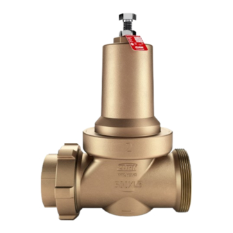
Model 500XL3
Pressure Reducing Valve
(2 1/2", 3" & 4")
*This product contains a weighted average lead content less than 0.25% for wetted surfaces.
*Meets the requirements of NSF/ANSI/CAN 61 & 372
Installation Testing Maintenance Instructions
INSTALLATION INSTRUCTIONS
Before installing reducing valve, flush out line to remove loose dirt and scale which might damage seal ring and seat. Install valve in
line with arrow on valve body pointing in direction of flow.
All valves will be furnished with stock settings to reduce to 50 psi. To readjust reduced pressure, loosen outer locknut and turn adjust-
ment bolt clockwise (into bell housing) to raise reduced pressure, or counterclockwise (out of bell housing) to lower reduced pressure.
CAUTION: Anytime a reducing valve is adjusted, a pressure gauge must be used downstream to verify correct pressure
setting. Do not bottom out adjustment bolt on bell housing. Valve may be installed in any position.
NOTICE: Annual inspection and maintenance is required of all plumbing system components. To ensure proper performance
and maximum life, this product must be subject to regular inspection, testing and cleaning. The valve shall be installed in
an accessible location. Also, it is recommended that a suitable strainer be installed upstream of the valve.
Due to highly efficient flow performance, it is not recommended to use a 1" or 1-1/4" 500XL3 as a standalone low flow bypass
valve in parallel. Instead, it is recommended that a 2-1/2", 3", or 4" 500XL3FBP be paired with a 1-500XL3BPK and used as a
low flow/high flow parallel PRV configuration. This configuration can be used in high flow, high pressure drop applications
that also will see low flow usage. Unlike the standard 500XL3, this 1-500XL3BPK can be used as a bypass valve due to a
restricting tailpiece included in this bypass configuration.
Regulators in series: Where the desired pressure reduction is more than a 3 to 1 ratio (i.e. 150psi to 50psi), multiple regulators
in series should be installed. The first regulator should be set to drop the pressure halfway to the desired outlet pressure.
High range valves are available with 60-125psi outlet pressure range.
Troubleshooting
Pipe lines in a water supply system must be of sufficient carrying capacity to maintain adequate pressure at the most remote or highest
fixture. Under the maximum probable fixture use, minimum adequate pressure is generally 8 to 15 psi but may be more, depending
on the equipment being supplied. Relatively high service pressures which can create high water velocities in pipe lines would allow
use of smaller pipes to satisfy fixture use. However, high velocity tends to cause whistling and humming. Reduction of pressure by
the use of a pressure reducing valve, in an attempt to eliminate such a condition, may reduce pipe line capacities below that which is
adequate for maximum probable use. When high service pressures are in effect, either continuously or periodically, the application of
a pressure reducing valve will be successful only when the installed pipe line is of adequate size to satisfy the system demand at the
lower pressure. When actual water demands are unknown, the valve size should be no less than the existing pipe size.
PROBLEM
1.
Pressure creeps or builds up in system above the
setting of pressure reducing valve.
SOLUTION
a.
This is a natural ocurrence. It may happen each time that the heater runs. A pressure relief valve or
expansion tank must be installed. This will not prevent pressure rise but should limit it to a safe level.
b.
Flush the reducing valve by opening one or two fixture outlets wide open. If this does not correct the problem,
wipe off the exposed surface of the seal ring with a rag.
c.
Install a new cartridge assembly.
d.
Install a new cartridge assembly.
2.
Pressure and fixture flow is unsteady.
SOLUTION
a.
This is a water department problem. It is due to the mains being inadequate for the demands made on them.
b.
Building service lines may at times be inadequate for the load. Size of some pipelines may need to be
increased, or pressure setting of reducing valve may be too low. Try increasing pressure before changing
pipelines.
3.
Small, inadequate flow from fixtures.
! WARNING: Cancer and Reproductive Harm - www.P65Warnings.ca.gov
! ADVERTENCIA: Cáncer y daño reproductivo - www.P65Warnings.ca.gov
! AVERTISSEMENT: Cancer et néfastes sur la reproduction - www.P65Warnings.ca.gov
LEAD-FREE*
POSSIBLE CAUSE OR CAUSES
A.
Thermal expansion of water as it is being heated.
B.
Foreign matter on seating face of seal ring.
C. Cut, worn or chipped seal ring.
D. Cut or worn stem o-ring or worn o-ring groove.
A.
Low water supply pressure in mains caused possibly
by high area demand during certain periods of the day.
B.
Heavy periodic demands by appliances in the building.
A.
Pipelines to fixtures may be too small or building main
supply may be inadequate for normal fixture demand.
B.
Heavy periodic demands by appliances in the building.
C. An upstream screen in a y-strainer may be clogged.
1747 Commerce Way, Paso Robles, CA 93446 Phone:855-663-9876 Fax:805-238-5766
ZURN WILKINS
1
www.zurn.com
Advertisement

Related Manuals for ZURN 500XL3


Summary of Contents for ZURN 500XL3
- Page 1 Also, it is recommended that a suitable strainer be installed upstream of the valve. Due to highly efficient flow performance, it is not recommended to use a 1" or 1-1/4" 500XL3 as a standalone low flow bypass valve in parallel.
- Page 2 If in any recommended service, a defect develops due to material or workmanship, and the device is returned, freight prepaid, to ZURN WILKINS within 12 months from date of purchase, it will be repaired or replaced free of charge. ZURN WILKINS’ liability shall be limited to our agreement to repair or replace the valve only.
Need help?
Do you have a question about the 500XL3 and is the answer not in the manual?
Questions and answers