
Related Manuals for SMC Networks FS1601 -


Summary of Contents for SMC Networks FS1601 -
- Page 1 EZ Switch™ EZ Connect N 16/24-Port Fast Ethernet Switch Draft 11n Wireless USB2.0 Adapter SMCFS1601/SMCFS2401...
-
Page 2: Fcc Statement
Specifications are subject to change without notice. is a registered trademark of SMC TECHNOLOGIES CO, LTD. Other brands and product names are trademarks or registered trademarks of their respective holders. No part of the specifications may be reproduced in any form or by any means or used to make any derivative such as translation, transformation, or adaptation without permission from SMC TECHNOLOGIES CO, LTD. -
Page 3: Table Of Contents
CONTENTS Package Contents....................1 Chapter 1 Product Introduction ...............2 Product Overview .....................2 Features ......................2 Chapter 2 Identifying External Components ...........2 Front Panel .......................3 Rear Panel......................3 Chapter 3 Installation ..................4 Precautions.......................4 Installation......................5 3.2.1 Desktop Installation.................5 3.2.2 Rack Installation..................6 Connect to Ground ...................7 Power on ......................8 Appendix A: Specifications..................9 Appendix B: Troubleshooting................10... -
Page 4: Package Contents
One power cord This User Guide Mounting screws and two “L” planks Quick Installation Guide SMC Warranty Card Four rubber foot pads Note: Make sure that the package contains the above items. If any of the listed items are damaged or missing, please contact with your distributor. -
Page 5: Chapter 1 Product Introduction
Chapter 1 Product Introduction This chapter describes the features of the model of SMCFS1601/SMCFS2401 16/24-Port 10/100Mbps Fast Ethernet Switch. 1.1 Product Overview SMCFS1601/SMCFS2401 Switch provides 16/24-Port 10/100Mbps Auto- Negotiation RJ45 ports. Each port of the SMCFS1601/SMCFS2401 supports auto MDI/MDI-X function, eliminating the need for crossover cables or Uplink ports. The Switch is Plug- and-Play and any port can be simply plugged into a server, a hub or a switch, using straight cable or crossover cable. -
Page 6: Front Panel
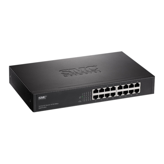
2.1 Front Panel The front panel of SMCFS2401 consists of switch model, switch LED indicators, and 24 10/100Mbps RJ-45 ports. Figure 2-1 SMCFS2401 Switch Front Panel sketch The LED indicators include Power, Link/Act LED indicators, which are used for monitoring and pre-troubleshooting of the Switch. The following section shows the LED indicators of the Switch along with an explanation of each indicator. -
Page 7: Chapter 3 Installation
Chapter 3 Installation 3.1 Precautions To ensure a long-term and stable performance of the Switch, please pay attention to the following before the installation. 1) Safety Requirements • Before cleaning the Switch, cut off the power supply. Do not clean it by the waterish cloth, and never use any other liquid cleaning method. -
Page 8: Installation
3.2 Installation This Switch can be either installed on the standard 19-inch mountable rack or located on the desktop. Caution: Please unplug the power cord before installing or removing the Switch. 3.2.1 Desktop Installation To install the Switch on the desktop, please follow the steps: 1) Set the Switch on a flat surface strong enough to support the entire weight of the Switch with all fittings. -
Page 9: Rack Installation
3.2.2 Rack Installation To install the Switch in an EIA standard-sized, 19-inch rack, follow the instructions described below: 1) Secure the supplied rack-mounting brackets to each side of the Switch with supplied screws, as illustrated in the following figure. Figure 3-2 Attaching Brackets 2) After the brackets are attached to the Switch, use suitable screws (not provided) to secure the brackets to the rack, as illustrated in the following figure. -
Page 10: Connect To Ground
3.3 Connect to Ground Connecting the Switch to ground is to quickly release the lightning over-voltage and over-current of the Switch, which is also a necessary measure to protect the body from electric shock. In different environments, the Switch may be grounded differently. The following will instruct you to connect the Switch to the ground in two ways, connecting to the Grounding Bar or connecting to the Ground via the power cord. -
Page 11: Power On
Figure 3-5 The figure is to illustrate the application and principle. The power plug you get from the package and the socket in your situation will comply with the regulation in your country, so they may differ from the figure above. Note: If you intend to connect the Switch to the ground via the PE (Protecting Earth) cable of AC power cord, please make sure the PE (Protecting Earth) cable in the... -
Page 12: Appendix A: Specifications
Appendix A: Specifications General Standards IEEE 802.3 10Base-T, IEEE 802.3u 100Base-TX Topology Star Protocol CSMA/CD Ethernet: 10Mbps (Half Duplex) 20Mbps (FullDuplex) Data Transfer Rate Fast Ethernet: 100Mbps (Half Duplex) 200Mbps (Full Duplex) 10Base-T: UTP category 3, 4, 5 cable (maximum 100m) EIA/TIA-568 100 STP (maximum 100m) Network Media... -
Page 13: Appendix B: Troubleshooting
Appendix B: Troubleshooting The Power LED is not lit Make sure the AC power cord connected the Switch with power source properly. Make sure the power source is ON. The Link/Act LED is not lit when a device is connected to the corresponding port Make sure that the cable connectors are firmly plugged into the Switch and the device. - Page 15 SMCFS1601/SMCFS2401 7109504046...
Need help?
Do you have a question about the FS1601 - and is the answer not in the manual?
Questions and answers