Advertisement
- 1 IMPORTANT SAFETY INSTRUCTIONS
- 2 Overview
- 3 Required equipment
- 4 Before you begin
- 5 Test for safe voltages
- 6 Uninstall the top of the unit
- 7 Install the new top of the unit
- 8 Reinstall communications components
- 9 Reinstall the unit covers
- 10 Power ON the device
- 11 Recommission the device
- 12 Documents / Resources
IMPORTANT SAFETY INSTRUCTIONS

Configuration of the power control settings system or changes to settings shall be made by qualified personnel only. Incorrect configuration or setting of the power control settings may result in unsafe conditions.
The controlled current settings shall not exceed the busbar rating or conductor ampacity of any PCS controlled busbar or conductor.
The maximum operating currents in controlled busbars or conductors are limited by the settings of the power control system (PCS) and may be lower than the sum of the currents of the connected controlled power sources. The settings of the PCS controlled currents may be used for calculation of the design currents used in the relevant sections of NEC Article 690 and 705.
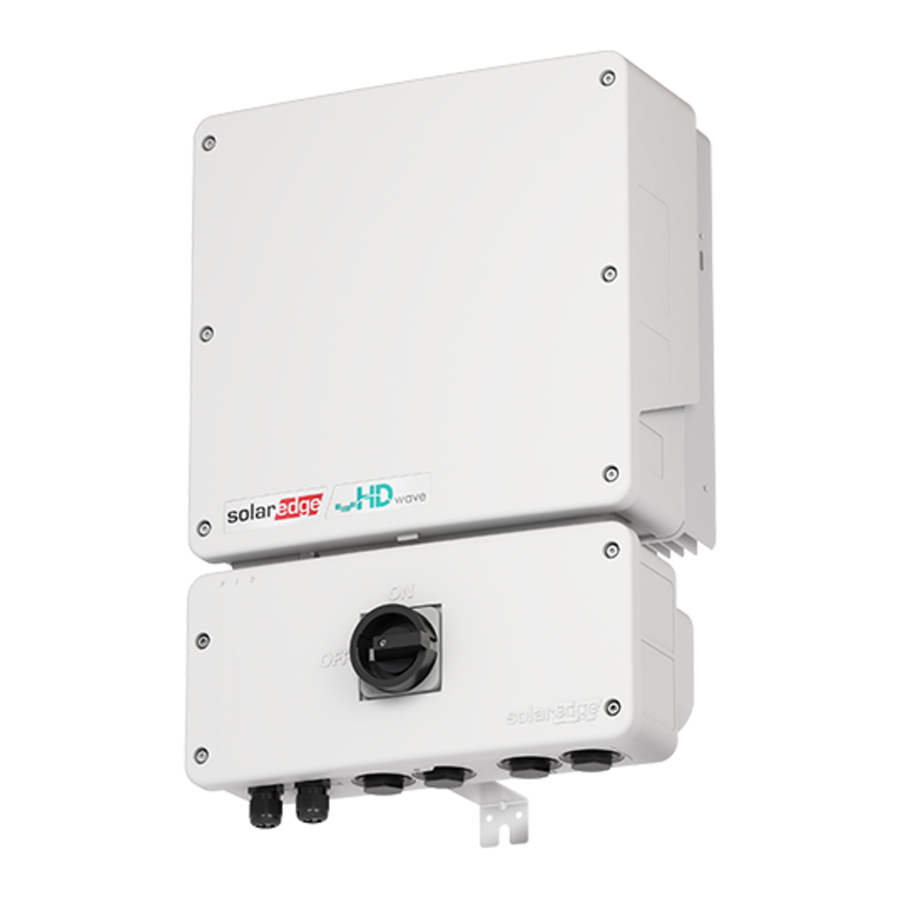
Overview
The application note explains how to replace the top part of the SolarEdge Home Hub inverter. You must install the inverter top on the original Safety Switch to maintain compatibility with the installed LG Chem RESU10h second generation batteries.
Required equipment
- #1 Phillips screwdriver
- Needle nose pliers
- Allen wrench
- Wire cutters
- Pliers
- Voltmeter
Before you begin
- Verify the meter and battery settings.
- Turn the P /1/0 switch to OFF (0) and wait at least five minutes for the capacitors to discharge.
- Turn DC Safety Switch to OFF.
- Turn the main AC breaker to OFF.
- Remove the DCD cover to verify the voltage has dropped to a safe level.
- Remove the inverter's front cover.
 NOTE
NOTE
We recommend that you remove the DCD cover to verify that the inverter has dropped to a safe level before removing the inverter cover.
- Verify there is no voltage at the AC terminal blocks of the inverter with a voltmeter.
Test for safe voltages
Before you disconnect any wires in the DC Disconnect (DCD) unit, you must test for safe voltages.
- Test at the DC terminals or in the upper cabinet to confirm that the switch is functioning properly and that the strings have the correct voltage.
- Test the string DC voltage at the terminals of the rotary switch in the DCD unit. The measured DC voltage should be ~1VDC per number of optimizers on that string. For example, if there are 20 Power Optimizers in a string, your measurement must be 20V ± 0.1V.
- If the voltage measured is greater or less than 1 volt per Power Optimizer, disconnect all the strings and take measurements in open air (open circuit) to find the string with the incorrect voltage.
- Inspect the string with the incorrect voltage to find the source of the voltage loss or gain.
Uninstall the top of the unit

- Disconnect the wires from the communication board.
- Take a picture of the AC and DC cable connections to the power board before you disconnect the wires.
- Disconnect the communications cables from the front of the communication board.
- Disconnect the antenna cable from the communications modem (if relevant).
- Remove communication devices from the original inverter and place them in a safe location.
- Remove the DC and AC conductors.
- Cut off the zip ties from the ferrite ring (choke) with the wire cutters.
- Remove the four screws with the #1 Philips screwdriver to detach DC conductors from the power board.
NOTE
Positive conductors are attached to the two terminals to the left.
Negative conductors are attached to the two terminals on the right.
- Unwind the DC cables through the ferrite ring (choke) and save the ring for the new inverter.
- Remove the four screws that attach the AC conductors to the power board with the #1 Phillips screwdriver. Save the screws to reattach the new inverter top.
- Remove the communications connector.

- Remove the communications connector on the bottom of the inverter with the needle nose pliers.
- Make sure to grasp the middle section of the connectors to release the metal clip holding it in place.

NOTE
- Positive conductors are attached to the two terminals to the left.
- Negative conductors are attached to the two terminals on the right.
- Guide the communications connectors to the top part of the inverter.
- Detach the top of the inverter.
- Pull the two locking clips outward to detach the top half of the inverter to the DCD unit.
![]()
- Remove the seismic screws on both sides of the inverter connecting it to the wall mount.
- Unwind the DC and AC conductors in preparation for the new unit.
- Pull the two locking clips outward to detach the top half of the inverter to the DCD unit.

NOTE
If there is a communication antenna connected to the inverter heatsink, disconnect, and save it for the new unit.
- Carefully remove the top of the inverter while guiding the DC and AC wires through their designated opening.
NOTE
Save the DC and AC conductors for the new inverter top.
Install the new top of the unit
If the existing mounting bracket is identical to the new one, continue fitting the new inverter.
- Mount the inverter.
- Carefully place the new inverter on top of the DCD unit.
- Mount the new bracket with seismic screws making sure that it aligns with the existing DCD unit.
- Guide the AC and DC conductors through the designated opening as follows:

- Guide communication cables through the left opening in the new inverter.

- Reattach the metal clips to the inverter mounting pins on top of DCD unit to connect the top to the bottom of the inverter.
- Reconnect the DC and AC conductors.
- Connect the AC wires to the AC terminals on the power board of the new inverter with a Phillips #1 screwdriver and tighten to 1.2N•m or 10.62lbf-in. Install the EMI filter between the neutral and ground terminals as shown in the picture below.

- Connect the AC wires to the AC terminals on the power board of the new inverter with a Phillips #1 screwdriver and tighten to 1.2N•m or 10.62lbf-in. Install the EMI filter between the neutral and ground terminals as shown in the picture below.


Wire the AC cables according to the order in the picture above. Failure to do so can result in injury or damage.
- Feed the DC conductors through the Ferrite ring (choke) twice.
- Attach the DC conductors to the new power board and tighten to 1.2N•m or 10.62in-lbs.
- Verify that the AC and DC wires are correctly landed and secured with the correct torque.

- Check that you correctly reinstalled the DC and AC cable connections with the photo.

Reinstall communications components

- Reinstall any accessories (Home net card, Cellular modem, or Zigbee module) from the previous unit.
- Reconnect any external antenna cable from the previous unit.
- Reconnect all communications connections to the DCD unit.
NOTE
- The connector must be connected to its designated location.
- Do not force its connection.
- Make sure that the connector is facing the correct position.
Reinstall the unit covers
- Reinstall both the front covers of both the inverter and DCD unit. Install new seismic screws.
- Tighten the covers with seismic screws.
- Record the new serial number for later use.
Power ON the device
- Turn ON the AC main breaker.
- Turn ON the DCD switch.
- Turn the P/1/0 switch to ON (0).
After the green LED indicator is blinking, continue with recommissioning the inverter.
Recommission the device
Make sure to pair the inverter using SetApp before recommissioning.
- Add Modbus communication.
- Open SetApp and scan the QR code to connect to the inverter. The firmware automatically updates.
- From the Main menu go to Commissioning > Site Communication > RS485-1 and tap Add Modbus Device.
- Confirm the following:
- Battery Protocol is LG
- Device ID is 15
For sites with two batteries, repeat Step 1 and set the Device ID to 14.
- Validate meter settings.
From Site Communication go to RS485-1 and validate the following:- Meter 1 is set to Function Production for systems with BUI.
- Meter 2 (only relevant if there is a BUI) is set to Export+Import (E+I)
- CT Rating is as follows:
- Blue current transformers: 200A
- White current transformers: 225A
- BUI with internal current transformers: 200A
- Run test.
From the Commissioning go to Maintenance > Diagnostics > Self Tests and tap Run Test.
After the Self Tests passes, continue with the next step. - Set mode of operation.
- From Commissioning go to Power Control > Energy Manager > Energy Control and select the type of operation mode.
NOTE
Make sure to use the previous settings for the meter and the battery.
- Enable Backup Configuration and then select the previous Backup Reserved value when there is a BUI on site.
- From Commissioning go to Status and the following:
- Status: ProductionS
- OK: Server Connected (LAN)
After the commissioning process is finished, confirm that the new inverter is registered under the site in the Monitoring platform.
Return the old inverter top to SolarEdge with the provided shipping label. For any troubleshooting issues, contact SolarEdge support.
To view Top Replacement: SolarEdge Home Hub Inverter video, scan the QR code:

Documents / ResourcesDownload manual
Here you can download full pdf version of manual, it may contain additional safety instructions, warranty information, FCC rules, etc.
Advertisement


Need help?
Do you have a question about the Home Hub Series and is the answer not in the manual?
Questions and answers