Advertisement
Quick Links
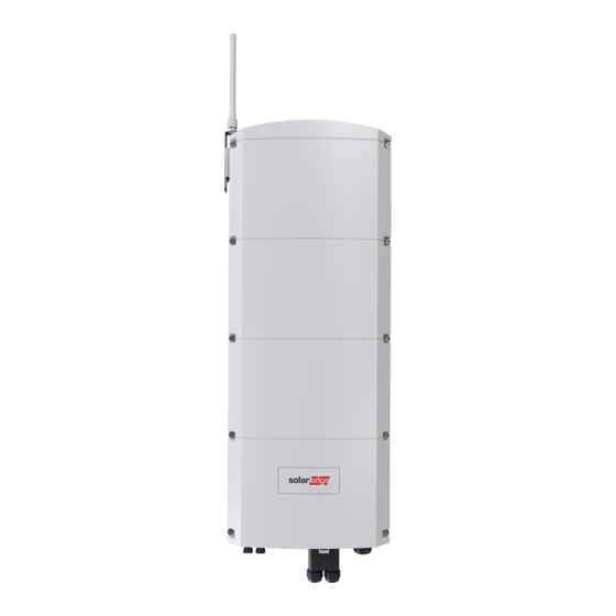
SolarEdge
Home Hub Inverter -Three Phase
Compact Product Guide
for Europe
Connection Diagram
The following figure shows a schematic connection diagram of the inverter.
Before Installing the Inverter
WARNING!
To avoid danger, read the HANDLING AND
1.
i
SAFETY INSTRUCTIONS provided with this product, or refer to:
https://www.solaredge.com/sites/default/files/se_handling_and_safety_in
structions.pdf
2. Read the datasheet provided with this product, or refer to:
https://www.solaredge.com/sites/default/files/se-Inline-energy-meter-
datasheet.pdf
Mounting Considerations
• Inverter Weight: 37 Kg. Use
provided bracket for
mounting.
• Clearance around the inverter:
keep 20 cm from the top and
bottom, 20 cm from the sides,
and one meter from the front.
• Tighten the side screws (3) to
a torque of 4 N*m.
• Tighten the screws of the
antenna bracket (5) to a
torque of 2.2 N*m.
The following figure shows how to mount
the inverter.
Unpacking and
mounting video
Quick Installation Guide
Inverter AC and DC Wiring
The following figure shows the AC and DC wiring of the inverter.
1. Enclosure Grounding wire: Use at least 6 mm
CAUTION! Connect a grounding cable to the enclosure first.
2. AC Terminals: Use a five-wire cable with a wire cross-section area of 6-16
mm
. The cable diameter is 15-21 mm. Use ferrules on the wires. Pass
2
the wires through the ferrite bead. Torque the terminal screws to 1.5
N*m. Tighten the AC gland to a torque of 2.8-3.3 N*m.
NOTE: Overcurrent protection for the AC output must be provided by
others, see installation manual for guidance.
CAUTION! Connect the grounding wire before the other wires.
3. PV String (DC power) MC4 Connectors
The cable diameter is 11-16.5 mm.
CAUTION! Earthing of a conductor on the DC side is not permitted.
Connecting Communications
To add a plug-in communication module: Plug in the module to the
communication board and route the antenna cable via glands COM1 or COM2.
Tighten the glands to a torque of 3.5 N*m.
Wiring video
Installation Manual
cross-section wire.
2
Datasheet
Advertisement

Related Manuals for SolarEdge Home Hub Inverter Three Phase


Summary of Contents for SolarEdge Home Hub Inverter Three Phase
- Page 1 Unpacking and Wiring video mounting video Datasheet SolarEdge Home Hub Inverter -Three Phase Quick Installation Guide Installation Manual Compact Product Guide for Europe Inverter AC and DC Wiring Connection Diagram The following figure shows the AC and DC wiring of the inverter.
- Page 2 Support Contact Information: If you have technical problems concerning SolarEdge products, please contact us: https://www.solaredge.com/service/support Subject to change without notice. Copyright © SolarEdge Inc. All rights reserved. August 2022.
Need help?
Do you have a question about the Home Hub Inverter Three Phase and is the answer not in the manual?
Questions and answers