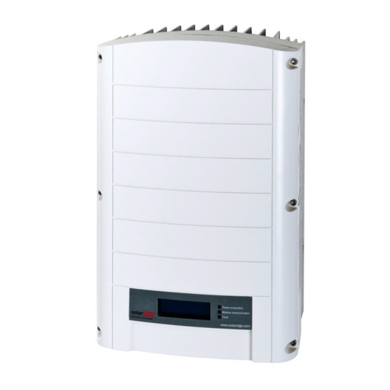
SolarEdge SE3500 Installation Manual

SolarEdge SE3500 Installation Manual

Hide thumbs Also See for SE3500:
Table of Contents

Advertisement

Advertisement

Table of Contents
loading

Summary of Contents for SolarEdge SE3500

  • Page 2: Legal Notice

    However, SolarEdge assumes no liability for the use of this equipment. SolarEdge reserves the right to make changes to the materials at any time without notice. You can refer to the website of SolarEdge (www.solaredge.com) for the latest updated version.
  • Page 3: Support Information And Contact

    The product serial number in question • The error indicated on the display of the inverter, or the SolarEdge Monitoring Portal, if such indication appears. • The system configuration information, including the type and the number of connected modules, and the number and length of the channels.
  • Page 4: Table Of Contents

    HANDLING INSTRUCTIONS AND SAFETY ..............6 SAFETY SYMBOLS ....................6 SAFETY INSTRUCTIONS ....................7 Chapter 1: System Overview SolarEdge ..............8 System Overview ......................8 SolarEdge Power Optimizer ..................8 SolarEdge Inverter ........................8 SolarEdge Monitoring Portal ..........
  • Page 5 Single phase UPS and Type 1 mount ............68 Three-phase UPS and Type 1 mount ............. 70 single phase inverter and mounting bracket Type 2 ............72 three-phase inverter and mounting bracket Type 2 ............. 73 SolarEdge Installation Guide - MAN-01-00060-2.6...
  • Page 6 Fan Interview ....................75 Replacing the fan 2 ..................75 Appendix F: Replacing and Adding System Components ........77 Replacing an inverter ..................77 Adding, removing, or replacing power optimizers ........77 SolarEdge Installation Guide - MAN-01-00060-2.6...
  • Page 7: Handling Instructions And Safety

    Do not proceed beyond a warning until the indicated conditions are fully understood and met. product. Do not proceed beyond a warning until the indicated conditions are fully understood and met. NOTE : Indicates additional information on the current topic. SECURITY ELEMENT IMPORTANT: Indicates information on security issues. SolarEdge Installation Guide - MAN-01-00060-2.6...
  • Page 8: Safety Instructions

    Use PV modules classified in accordance with the IEC 61730 standard class A. NOTE : The symbol appears to grounding points on the SolarEdge equipment. This symbol is also used in this manual. NOTE : The following warning symbols appear on the warning label...
  • Page 9: Chapter 1: System Overview Solaredge

    SolarEdge inverter The inverter SolarEdge effectively converts the DC power from AC power modules which can be introduced into the main AC terminal site and from there to the power line. The inverter also receives each power optimizer surveillance data and transmits them to a central server (the SolarEdge Monitoring Portal;...
  • Page 10: Installation Procedure

    Chapter 1: System Overview SolarEdge Installation procedure The following section is to describe the procedure for installing and configuring a new site SolarEdge. Many items also apply to the modification of an existing site. Connecting the power optimizers and the modules on a chain...
  • Page 11: List Of The Installed Equipment

    Chapter 1: System Overview SolarEdge List of installation equipment Standard tools can be used for installation of the SolarEdge system. The following is a recommendation of the equipment required for installation: • Allen screwdriver for M6 / M8 screws •...
  • Page 12: Chapter 2: Construction Of

    SECURITY ELEMENT IMPORTANT: The modules with SolarEdge power optimizers are safe. They have only a low safety voltage before the inverter is switched on. As power optimizers are not connected to the inverter or the inverter is in the OFF position, each power optimizer will output a safe 1V voltage.
  • Page 13: Installation Instructions

    The guidelines for minimum and maximum length of the chain are set out in the specifications of the power optimizer. • Refer to the SolarEdge site designer for verification of the chain length. The site designer SolarEdge is available on the website of the SolarEdge http://www.solaredge.fr/groups/support/downloads http://www.solaredge.fr/groups/support/downloads...
  • Page 14: Step 2, Connecting A Module To A Power Optimizer

    You can build strings in parallel of unequal length, that the number of power optimizers on each channel may be different. maximum and minimum chain lengths are shown in the data sheet of power optimizers. Refer to the SolarEdge site designer for verification of the chain length. NOTE : The string length must not exceed 300m from the CC + to CC UPS.
  • Page 15: Step 4, The Correct Connection Checking The Power Optimizer

    For more information on the voltage and current string of SolarEdge systems, refer to the Technical Note V systems. For more information on the voltage and current string of SolarEdge systems, refer to the Technical Note V systems.
  • Page 16 2 For troubleshooting problems with operation of power optimizers, see 2 For troubleshooting problems with operation of power optimizers, see you Troubleshooting power optimizers on page 60. you Troubleshooting power optimizers on page 60. you Troubleshooting power optimizers on page 60. SolarEdge Installation Guide - MAN-01-00060-2.6...
  • Page 17: Chapter 3: Installation Of The Inverter

    Refer to the sticker on the UPS indicating its Serial number and his Electrical Specifications. Report serial number when you contact SolarEdge support. The serial number is also required when opening a new site in the SolarEdge Monitoring Portal. In the following sections, unless otherwise indicated, instructions apply to the inverters both single and three phase, although only one graphic example is presented.
  • Page 18 DC inputs: for connection of the PV system DC inputs: for connection of the PV system WARNING : Do not remove the six screws CC metal panel since it can damage the sealing on the inverter and void the warranty. SolarEdge Installation Guide - MAN-01-00060-2.6...
  • Page 19: Mounting The Inverter

    To allow for heat dissipation, keep sufficient space between the UPS and other objects: • 20 cm / 8 "at the top and the bottom of the inverter • 10 cm / 4 "to the right and to the left of the inverter SolarEdge Installation Guide - MAN-01-00060-2.6...
  • Page 20 For type 1 - Use the screws on the top of the inverter as shown below. Leave the flat inverter against the wall or pole. Figure 7: Hang the inverter on the bracket - Type 1 SolarEdge Installation Guide - MAN-01-00060-2.6...
  • Page 21 Insert two screws through the fin outside the heat sink on both sides of the inverter and in the support. Tighten the screws using a torque of 4.0 N * m / 2.9 ft * lb. type support 2 media type 1 Bracket Screw Bracket Screw Figure 9: Insertion of the stand mounting SolarEdge Installation Guide - MAN-01-00060-2.6...
  • Page 22: Ac Connection To The Inverter

    WARNING : When removing the lid, make sure not to damage internal components. SolarEdge can not be held responsible for any damage resulting component imprudent removal of the cover. 3 insulating strip of 58 mm / 2.32 "of the external cable and insulating tape 8 mm / 0.32" internal thread.
  • Page 23 9 Check that there is no not connected to the inverter wire and screws are unused terminals 9 Check that there is no not connected to the inverter wire and screws are unused terminals tight. SolarEdge Installation Guide - MAN-01-00060-2.6...
  • Page 24: Connection Strings To The Inverter

    PV modules is admitted .. NOTE : The fixed input voltage SolarEdge architecture allows parallel channels being of different lengths. Therefore, they do not need to have the same number of power optimizers, as the length of each string is within the allowed limits.
  • Page 25: Chapter 4: Commissioning Of The Facility

    A similar status screen the following appears on the LCD panel of the UPS: V ac [v] V dc [v] P ac [w] 2 4 0, 7 1 4, 1 0, 0 P _ OK: 0 0 0/0 0 0 <S _ OK> SolarEdge Installation Guide - MAN-01-00060-2.6...
  • Page 26: Step 2, Pairing Power Optimizers To The Inverter

    • S_OK: the connection to the SolarEdge Monitoring Portal is successful (should appear only if the inverter is S_OK: the connection to the SolarEdge Monitoring Portal is successful (should appear only if the inverter is connected to the server).
  • Page 27: Step 3 Check The Health

    4 Wait until completion of the coupling (seconds remaining is 0). If the pairing fails, error message is displayed. In this case, repeat the coupling steps. If the problem persists, contact SolarEdge support. When the pairing is successful, the following message appears:...
  • Page 28: Step 4, Reporting And Monitoring Installation Data

    The logical and physical mapping can be used to solve a problem using the SolarEdge Monitoring Portal. If you have not sent the physical mapping of the installed power optimizers SolarEdge Monitoring Portal will show the logical layout indicating which power optimizers are connected to which inverter, but will not show strings or the physical location of optimizers power.
  • Page 29: Provide Information On Installing

    Chapter 4: Commissioning of the facility The inverter may be connected to SolarEdge Monitoring Portal via a LAN or via an external modem connected to the RS232 port of the UPS. Alternatively, you can connect the UPS to another UPS already connected to the server, in a master-slave configuration.
  • Page 30: Chapter 5: User Interface

    A: Errors and Troubleshooting on page 52 and UPS configuration using the user buttons on page 30 for more A: Errors and Troubleshooting on page 52 and UPS configuration using the user buttons on page 30 for more information. SolarEdge Installation Guide - MAN-01-00060-2.6...
  • Page 31: Ups Configuration - Setup Mode

    The following illustration shows the hierarchical tree of the menu options, which are described in the Options in The following illustration shows the hierarchical tree of the menu options, which are described in the Options in the setup menu Page 34 the setup menu Page 34 SolarEdge Installation Guide - MAN-01-00060-2.6...
  • Page 32 If Wi-Fi is connected, the ZigBee Conf menu is not displayed and vice versa. If Wi-Fi is connected, the ZigBee Conf menu is not displayed and vice versa. The phase balancing is applicable to single phase inverters only. The phase balancing is applicable to single phase inverters only. SolarEdge Installation Guide - MAN-01-00060-2.6...
  • Page 33: Ups Configuration With The Light Button On The External Lcd

    M aintenirbout. app. pr. match. L cherpourallermenu R est 3 sec Release the button displays the following menu: A ppair. O ptimisr. L angue <eng> C ommunication I nfo M aintenance S nettle SolarEdge Installation Guide - MAN-01-00060-2.6...
  • Page 34 The options in these menus are described in the following section. If Wi-Fi is connected, the ZigBee item does not appear and vice versa. If Wi-Fi is connected, the ZigBee item does not appear and vice versa. SolarEdge Installation Guide - MAN-01-00060-2.6...
  • Page 35: Options Ups Configuration Menu

    2 Select Server to define which mode of communication is used for communication between the inverter and the SolarEdge Monitoring Portal. Refer to Chapter 6: Communication Setup on page 43 for between the inverter and the SolarEdge Monitoring Portal. Refer to Chapter 6: Communication Setup on page 43 for between the inverter and the SolarEdge Monitoring Portal.
  • Page 36 RS232 (next page) I / O Config. (next page) If Wi-Fi is connected, the ZigBee elements do not appear and vice versa. If Wi-Fi is connected, the ZigBee elements do not appear and vice versa. SolarEdge Installation Guide - MAN-01-00060-2.6...
  • Page 37 NOTE : The Phase Balancing is only applicable on single-phase inverters. For detailed information, refer to SolarEdge phase balancing Manual, available on The Phase Balancing is only applicable on single-phase inverters. For detailed information, refer to SolarEdge phase balancing Manual, available on The Phase Balancing is only applicable on single-phase inverters.
  • Page 38 • Date and hour : used to set the real time clock. If you are connected to the SolarEdge Monitoring Portal to the Date and hour : used to set the real time clock. If you are connected to the SolarEdge Monitoring Portal to the date and time are automatically configured and only the time zone must be set.
  • Page 39: Displays The Status Of The Ups - Operating Mode

    ​ ​ d iffer, there may be a problem in one or more power optimizers. • S_OK: The connection to the Monitoring Portal SolarEdge successful (appears only if the inverter is connected to the server). S_OK: The connection to the Monitoring Portal SolarEdge successful (appears only if the inverter is connected to the server).
  • Page 40: Statute Of The Energy Meter

    If the meter is installed at the connection point to the network, this value is the energy supplied to the network. If the inverter is connected to the SolarEdge server, this value will also be displayed in the monitoring portal.
  • Page 41: Status Id

    • RSSI: the intensity of the power of the ZigBee the reception signal closest in the SolarEdge system. L = low, M = RSSI: the intensity of the power of the ZigBee the reception signal closest in the SolarEdge system. L = low, M = medium, H = high and () = no signal.
  • Page 42: Wi-Fi State

    • RSSI: The indication of the received signal strength of the Wi-Fi closest in the SolarEdge system. L = low (weak), M = medium (Medium), RSSI: The indication of the received signal strength of the Wi-Fi closest in the SolarEdge system. L = low (weak), M = medium (Medium), RSSI: The indication of the received signal strength of the Wi-Fi closest in the SolarEdge system.
  • Page 43: Status Fan Status - Three-Phase Ups

    Note application of energy control, available on the website of SolarEdge • http://www.solaredge.com/files/pdfs/application_note_power_control_configuration.pdf Application Note on the power limit, available on the website of SolarEdge to Application Note on the power limit, available on the website of SolarEdge to •...
  • Page 44: Chapter 6: Configuring Communications

    DC power supply lines (the output circuit PV). No wires or configuration is required for this purpose. The information is then sent from the inverter to the SolarEdge Monitoring Portal Internet. To send data from the inverter, a communication link to be established, as described in this chapter.
  • Page 45: Communication Types

    WARNING : When removing the lid, make sure not to damage internal components. SolarEdge can not be held responsible for damaged components as a result of carelessness in removing the cover. An additional option of Internet connection using an 8-pin terminal block is also available. See An additional option of Internet connection using an 8-pin terminal block is also available.
  • Page 46: Creating An Ethernet (Lan)

    The UPS connection does not support changes polarity RX / TX. The management of Ethernet crossover cables depends on the capabilities of the switch. The UPS connection does not support changes polarity RX / TX. The management of Ethernet crossover cables depends on the capabilities of the switch. SolarEdge Installation Guide - MAN-01-00060-2.6...
  • Page 47 Use a crimping tool to crimp the connector. • Use a crimping tool to crimp the connector. • Connect the Ethernet connector to the RJ45 plug on the communication board of the inverter. RJ45 Ethernet interface Figure 20: RJ45 Ethernet connector SolarEdge Installation Guide - MAN-01-00060-2.6...
  • Page 48: Creating An Rs485 Bus Connection

    / router or on different switches / routers, if applicable. Each inverter sends its data independently controlled on the SolarEdge Monitoring Portal. 6 The inverters are configured by default LAN. If the reconfiguration is required: 6 The inverters are configured by default LAN.
  • Page 49 You can use any color thread for each connection A, B and BOY WUT, so that the same color thread is used for all the pins A, the same color for all the pins B and the same color for all G. Pines SolarEdge Installation Guide - MAN-01-00060-2.6...
  • Page 50 Figure 24: Termination switch RS485 NOTE : Only the first and last device in the chain SolarEdge be on ons. The other inverters in the chain must have the terminating switch to OFF (lowered position). SolarEdge Installation Guide - MAN-01-00060-2.6...
  • Page 51: Creating A Zigbee Connection

    The wireless kit can be purchased separately and assembled during the installation of the system. The wireless kit comes with a user manual, which must be consulted before connecting. It is available on the website of SolarEdge at a user manual, which must be consulted before connecting. It is available on the website of SolarEdge at http://www.solaredge.com/groups/pr...
  • Page 52: Connection Verification

    <S _ OK> S_OK: indicates that the connection to the SolarEdge Monitoring Portal was successful. If S_OK does not appear, see Appendix S_OK: indicates that the connection to the SolarEdge Monitoring Portal was successful. If S_OK does not appear, see Appendix S_OK: indicates that the connection to the SolarEdge Monitoring Portal was successful.
  • Page 53: Appendix A: Errors And Troubleshooting

    (phy-link indication). If OK contact your IT network, otherwise replace the first switch / r routeu defective local (LAN error) cable or change it to a cross connection in a direct connection SolarEdge Installation Guide - MAN-01-00060-2.6...
  • Page 54 3 Check that the selected communication option is configured correctly. 4 Use a method independent of the SolarEdge inverter to check whether the network and modem 4 Use a method independent of the SolarEdge inverter to check whether the network and modem working properly.
  • Page 55: Error Codes

    - Three-phase UPS on page 42 (a replacement kit is available from SolarEdge). 4, 5, 8, 45, 48, 50-53, software error Internal software error If the error persists, contact SolarEdge 12, 18-23, 94, 108- support. 111,113 39, 42, 45 Wrong AC connection The connections...
  • Page 56 Do not connect strings with an error grounded at the inverter. • For documentation on the possible motives of ground current error and solutions, contact SolarEdge support. • An approved installer must fix the faulty string before connecting to the inverter. SolarEdge Installation Guide - MAN-01-00060-2.6...
  • Page 57 Use a larger gauge wire for the AC output • Refer to the AC wiring Application Note Refer to the AC wiring Application Note available on the website of SolarEdge at http://www.solaredge.com/files /pdfs/application-noterecommended-wiring.pdf DC Voltage Too High DC overvoltage. The DC input...
  • Page 58 Make sure no dirt or obstruction is present in the fins of the heat sink. • Reinstall the UPS in a cooler location Failure Temp Sensor. Temperature sensor If the fault persists, contact SolarEdge N / A broken or not support. connected.
  • Page 59 CA. • Consult the network operator. • If permitted by local authorities, use the SolarEdge Configuration Tool to change settings. • 32, 41 61/62/63, AC Voltage Too Low The voltage network Check that the inverter is configured to...
  • Page 60 Refer to Reg. power on page 36 and the balancing Manuel phases on page 36 and the balancing Manuel phases SolarEdge available on the website of SolarEdge at SolarEdge available on the website of SolarEdge at http://www.solaredge.com/files/pdf s / phase_balancing_connection_guid e.pdf...
  • Page 61: Troubleshooting Power Optimizers

    Enable SafeDC using SolarEdge key previously been disabled using the key SolarEdge Power optimizers are shaded If you have connected the inverter to the SolarEdge Monitoring The coupling of the UPS Portal using one of the communication options, you can perform failed remote coupling.
  • Page 62: Appendix B: Specifications

    4985W when the country is set for Australia and 4600W in Germany or the Czech Republic. 16A when the country is set to Denmark, Portugal, the UK and Poland. For other countries, contact SolarEdge. 16A when the country is set to Denmark, Portugal, the UK and Poland. For other countries, contact SolarEdge.
  • Page 63 Appendix B: Specifications sE2200 SE3000 SE3500 SE4000 SE4000 SE5000 SE6000 Unit - 16A Maximum input voltage nominal DC input voltage Maximum Input Current 11.5 13.5 15.5 15.5 19.5 Maximum recharge current Protection against polarity reversal Grounding fault detection Sensitivity 600 kOhms...
  • Page 64 2000 Classification Pollution Degree (interior Exterior) Mounting support (Support supplied) Available in Germany, Austria and Denmark; for other countries, contact SolarEdge. Available in Germany, Austria and Denmark; for other countries, contact SolarEdge. SolarEdge Installation Guide - MAN-01-00060-2.6...
  • Page 65: Three Phase Inverters

    154/0050 A / ms maximum fault current output power factor range + / - 0.9 to 1.0 Protection class class I Utility Monitoring, islanding protection, power factor configurable, configurable thresholds countries category protection against overvoltage SolarEdge Installation Guide - MAN-01-00060-2.6...
  • Page 66 WEEE Compliant Specifications in stalling Specifications in stalling AC output Diameter press étoupe- diameter 15-21 DC input 2 pairs of MC4 Limited to 135% of the power CA. Limited to 135% of the power CA. SolarEdge Installation Guide - MAN-01-00060-2.6...
  • Page 67 2000 Pollution degree classification (interior Exterior) Mounting support (support provided) Breaker Size / fuse recommended to use the point of the SolarEdge inverter on the network connection: maximum output current Inverter Caliber Suggested fuse (A) sE2200 SE3000 16.5 SE3500 19.5...
  • Page 68 Appendix B: Specifications maximum output current Inverter Caliber Suggested fuse (A) sE2200 SE16k 25.5 SE17k SolarEdge Installation Guide - MAN-01-00060-2.6...
  • Page 69: Appendix C: Mechanical Specifications

    Type 1 - Weight of the mounting bracket 2.87 lbs. / 1.3 kg Type 2 - Weight Mounting Bracket 0.9 lbs. / 0.4 kg Single phase UPS and Type 1 mount Figure 25: Single-phase inverter with a media type 1 - Front and Rear view SolarEdge Installation Guide - MAN-01-00060-2.6...
  • Page 70 Appendix C: Mechanical Specifications Figure 26: Single-phase inverter with a media type 1 - side view and from above Figure 27: Mounting bracket of the single-phase inverter - Type 1 SolarEdge Installation Guide - MAN-01-00060-2.6...
  • Page 71: Three-Phase Ups And Type 1 Mount

    Three-phase UPS and Type 1 mount Figure 28: Three phase inverter with a media type 1 - Front and Rear view Figure 29: Three phase inverter with a media type 1 - side view and from above SolarEdge Installation Guide - MAN-01-00060-2.6...
  • Page 72 Appendix C: Mechanical Specifications Figure 30: Mounting bracket of the three-phase inverter - Type 1 SolarEdge Installation Guide - MAN-01-00060-2.6...
  • Page 73: Single Phase Inverter And Mounting Bracket Type 2

    Appendix C: Mechanical Specifications single phase inverter and type 2 bracket Figure 31: single-phase inverter with a media type 2 - view of front, side and rear Figure 32: Mounting bracket of the three-phase inverter - Type 2 SolarEdge Installation Guide - MAN-01-00060-2.6...
  • Page 74: Three-Phase Inverter And Mounting Bracket Type 2

    Appendix C: Mechanical Specifications three-phase inverter and type 2 bracket Figure 33: Three phase inverter with a media type 2 - view of front, side and rear Figure 34: Mounting bracket of the three-phase inverter - Type 2 SolarEdge Installation Guide - MAN-01-00060-2.6...
  • Page 75: Appendix D: Safety Cc

    OFF of the inverter is OFF, the DC voltage drops to a 1V voltage safety voltage optimizer. SolarEdge inverters are certified to the following standards as disconnection devices for PV generators, which means that they can replace a disconnected DC: •...
  • Page 76: Appendix E: Maintenance And Replacement Of Fan

    Appendix E: Maintenance and Replacement The three-phase inverter has two fans, one internal and requires a SolarEdge technician to replace it (fan 1) and the other is accessible from the outside of the inverter (fan 2). A replacement kit is available from SolarEdge.
  • Page 77 8 Check Status fan status - as described on page 42. 8 Check Status fan status - as described on page 42. 8 Check Status fan status - as described on page 42. 8 Check Status fan status - as described on page 42. SolarEdge Installation Guide - MAN-01-00060-2.6...
  • Page 78: Appendix F: Replacing And Adding System Components

    5 In the Monitoring Portal, replace the series of power optimizer number retired with 5 In the Monitoring Portal, replace the series of power optimizer number retired with the serial number of the new installed power optimizer. SolarEdge Installation Guide - MAN-01-00060-2.6...

Table of Contents