Table of Contents

Related Manuals for DX Engineering Chameleon Antenna CHA SOTA AZ-2


Summary of Contents for DX Engineering Chameleon Antenna CHA SOTA AZ-2
- Page 1 SOTA Activation Zone Model 2 40, 30, and 20m Linked Dipole Antenna (CHA SOTA AZ-2) Operator’s Manual Designed & Manufactured by Chameleon Antenna for DX Engineering VERSATILE – DEPENDABLE – STEALTH – BUILT TO LAST Rev. 10/07/2024...
-
Page 2: Table Of Contents
Table of Contents Introduction .............................. 3 HF Propagation ............................4 Parts of the Antenna ..........................6 Assembly ..............................8 Installation .............................. 10 Operation ..............................12 Recovery Procedure ..........................12 Troubleshooting ............................13 Specifications ............................13 References .............................. 14 Chameleon Antenna Products ...................... -
Page 3: Introduction
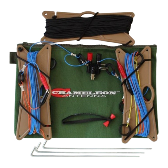
Introduction Thank you for purchasing and using the Chameleon Antenna SOTA Activation Zone Model 1 40, 30, and 20m Linked Dipole Antenna (CHA SOTA AZ-2). The CHA SOTA AZ-2, shown in plate (1), is designed specifically for the demanding conditions and constraints encountered during Summits on the Air (SOTA) activations or other extreme outdoor radio sports. -
Page 4: Hf Propagation
HF Propagation HF radio provides relatively inexpensive and reliable local, regional, national, and international voice and data communication capability. It is especially suitable for undeveloped areas where normal telecommunications are not available, too costly or scarce, or where the commercial telecommunications infrastructure has been damaged by a natural disaster or military conflict. - Page 5 due to ionospheric loses. The OWF, which is somewhere between the LUF and around 80% of the MUF, is the range of frequencies which can be used for reliable communication. If the LUF is above the MUF, HF sky wave propagation is unlikely to occur. The HF part of the Radio Frequency (RF) spectrum is usually filled with communications activity and an experienced operator can often determine where the MUF is, and with less certainty, the LUF by listening to where activity ends.
-
Page 6: Parts Of The Antenna
Parts of the Antenna The CHA SOTA AZ-2 is comprised of the following components, refer to plate (2): Plate 2. SOTA AZ-2 Components. A. Center Connector. The Center Connector is a BNC female to dual banana jack/binding post adaptor used as the center connection point for the dipole antenna. The Antenna Wires are connected to the binding posts and the BNC female connector is used to connect the Coaxial Cable. - Page 7 Band Set Wire Color 20 Meters BLUE 30 Meters ORANGE 40 Meters YELLOW Table 2. Antenna Wire Band Set Color. C. Bongo Tie. The Bongo Tie is a general-purpose temporary fastener. A typical use for the Bongo Tie is to attach the Center Connector to a telescoping mast. D.
-
Page 8: Assembly
Assembly Use the following procedure to assemble the components of the CHA SOTA AZ-2 before first deployment. Refer to figure (1). Figure 1. Antenna Wire Connection Details (one side shown). 1. Carefully cut off the wire ties holding the 4. Attach the Isolation Rings from the Antenna Wires (B) and Micro-Paracord unconnected ends of the 20-meter (H) hanks together. - Page 9 7. Wind the Antenna Wires and Micro- 8. Place all components into the OD Pouch Paracord onto their respective Line (K) and you are ready for deployment. Winders (D) and secure with attached shock cord. SOTA AZ-2 Page 9...
-
Page 10: Installation
Installation Using the supplied components, the CHA SOTA AZ-2 can be deployed as either a Horizontal Dipole or Inverted “V” using a tree or other structure as a support. The Inverted “V” is the usual configuration used when portable because it requires only one center support. Use the procedure below to install the CHA SOTA AZ-2 in an Inverted “V”... - Page 11 long Micro-Paracord over the center support. 7. Raise the Center Connector to the desired height (15-25 feet) and secure the free end of the Micro-Paracord. 8. Using a Bowline or similar knot, tie a short length (around six feet) of Micro- Paracord to the Isolation Rings on the ends of the two Antenna Wires.
-
Page 12: Operation
Operation The CHA SOTA AZ-2 is a Linked Dipole antenna and can operate one band at-a-time. Use Table (3) to set the Links for the band on which you want to operate. Connect the band Links by clamping the Alligator Clips together, as shown in plate (5). Set the Links the same on both sides of the dipole. -
Page 13: Troubleshooting
Troubleshooting 1. Ensure the Links are set correctly for the band on which you want to operate. 2. Ensure the Wire Ends of the Antenna Wires are securely connected to the binding posts of the Center Connector. 3. Inspect the Antenna Wires for breakage or signs of strain. 4. -
Page 14: References
Figure 3. 30m Inverted “V” SWR Graph. Figure 4. 20m Inverted “V”``` SWR Graph. References 1. Silver, H. Ward (editor), 2013, 2014 ARRL Handbook for Radio Communications, 91 Edition, American Radio Relay League, Newington, CT. 2. 1987, Tactical Single-Channel Radio Communications Techniques (FM 24-18), Department of the Army, Washington, DC. -
Page 15: Chameleon Antenna Tm Products
Products Go to http://chameleonantenna.com for information about quality antenna products available for purchase from Chameleon Antenna – The Portable Antenna Pioneer. Warranty information is available at http://chameleonantenna.com. Designed & Manufactured by Chameleon Antenna for DX Engineering SOTA AZ-2 Page 15...
Need help?
Do you have a question about the Chameleon Antenna CHA SOTA AZ-2 and is the answer not in the manual?
Questions and answers