Table of Contents
Advertisement
Quick Links
HARBOR BREEZE and logo design are trademarks or
registered trademarks of LF, LLC. All rights reserved.
Purchase Date _________________________
Thank you for purchasing this HARBOR BREEZE product.
Questions, problems, or missing parts?
Before returning, contact us at:
888-251-1003, 8 a.m. - 8 p.m., EST, Monday - Sunday or at ascs@lowes.com.
SG24510
ITEM #5971301/5979026/5979027/5979028
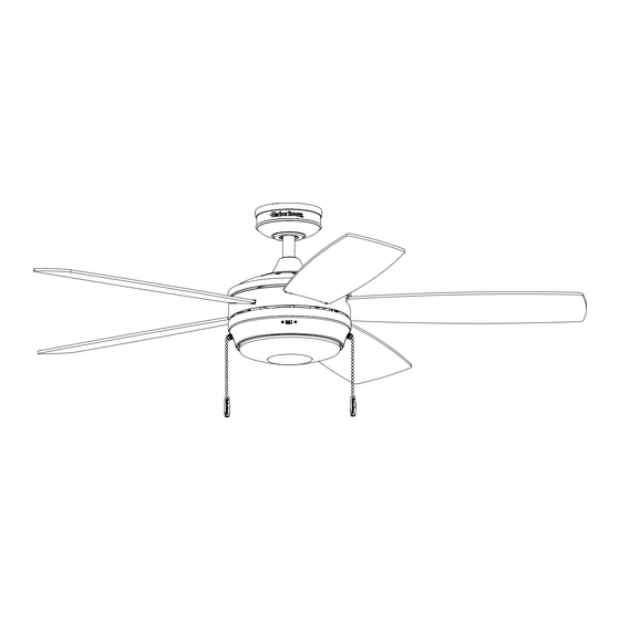
BRENTHAVEN CEILING FAN
MODEL #43295/43296/43374/43375
ATTACH YOUR RECEIPT HERE
Español p. 19
Advertisement
Table of Contents

Related Manuals for Harbor Breeze BRENTHAVEN 43295


Summary of Contents for Harbor Breeze BRENTHAVEN 43295
- Page 1 MODEL #43295/43296/43374/43375 BRENTHAVEN CEILING FAN Español p. 19 ATTACH YOUR RECEIPT HERE HARBOR BREEZE and logo design are trademarks or registered trademarks of LF, LLC. All rights reserved. Purchase Date _________________________ Thank you for purchasing this HARBOR BREEZE product. Questions, problems, or missing parts? Before returning, contact us at: 888-251-1003, 8 a.m.
-
Page 2: Table Of Contents
TABLE OF CONTENTS Package Contents ..............3 Hardware Contents . -
Page 3: Package Contents
PACKAGE CONTENTS PART DESCRIPTION QUANTITY Downrod Downrod Pin (preassembled to the Downrod [A]) Downrod Clip (preassembled to the Downrod [A]) Mounting Bracket (preassembled to Canopy [E]) Canopy Yoke Cover Set Screw (preassembled to the Motor Assembly [H]) Motor Assembly Fitter Plate (preassembled to the Motor Assembly [H]) Fitter Plate Screw (preassembled to Fitter Plate [I]) Light Pan Light Pan Screw (preassembled to Light Pan [K]) -
Page 4: Hardware Contents
HARDWARE CONTENTS Wire Connector Blade Screw Blade Washer Pull Chain Push-In Qty. 1 Qty. 15 Qty. 15 Extension Connector + 1 extra + 1 extra + 1 extra Qty. 2 1 extra Lead Wire Qty. 1... -
Page 5: Safety Information
SAFETY INFORMATION Please read and understand this entire manual before attempting to assemble, operate or install the product. • Before you begin installing the fan, disconnect the power by removing fuses or turning off the circuit breakers. • Make sure all electrical connections comply with local codes, ordinances, the National Electrical Code and ANSI/NFPA 70-199. -
Page 6: Preparation
SAFETY INFORMATION CAUTION: Read all instructions and safety information before installing your new fan. Review the accompanying assembly diagrams. CAUTION: Be sure the outlet box is properly grounded or that a ground (green or bare) wire is present. CAUTION: Carefully check all screws, bolts and nuts on the fan motor assembly to ensure they are secured. -
Page 7: Initial Installation
INITIAL INSTALLATION 1. Turn off the circuit breakers and the wall switch to the fan supply line leads. DANGER: Failure to disconnect the power supply prior to installation may result in serious injury or death. 2. Determine the mounting method to use. Standard Mounting is best suited for ceilings 8 ft. - Page 8 INITIAL INSTALLATION 4. Firmly hold canopy (E) while twisting the mounting bracket (D) counterclockwise to remove. 5. Attach mounting bracket (D) to outlet box (not included) using screws and washers provided with Standard Mounting the outlet box. CAUTION: It is very important to use the proper hardware when installing the mounting bracket (D) as this will support the fan.
-
Page 9: Standard Or Angle Mounting Instructions
STANDARD OR ANGLE MOUNTING INSTRUCTIONS 1. Remove the downrod clip (C) and downrod pin (B) from the downrod (A). Then partially loosen the set screws (G) in the yoke at the top of the motor assembly (H). Yoke 2. Insert the downrod (A) -- or a longer downrod (not included), if required -- through the canopy (E) and yoke cover (F). - Page 10 STANDARD OR ANGLE MOUNTING INSTRUCTIONS 4. Depending on the length of downrod (A) you use, you may need to use the 36-inch lead wire (O) to accommodate a 36 or 48-inch downrod (sold separately). When necessary, connect the 3-pin connector extending from the center of the downrod (A) to one end of the 36-inch lead wire (O).
- Page 11 STANDARD OR ANGLE MOUNTING INSTRUCTIONS Connect the 3-pin connector extending from the Bare/Green downrod (A) to the 3-pin connector on lead wire (AI). (ground) Then, connect the green/bare (ground) supply wire to the green wires from the downrod (A) and the mounting bracket (D).
- Page 12 STANDARD OR ANGLE MOUNTING INSTRUCTIONS 10. Remove one of the three fitter plate screws (J) preassembled to the fitter plate (I) and loosen the other two but do not remove. Feed the 9-pin connector through center hole in light pan (K). Align the three key slots in the light pan (K) with the loosened fitter plate screws (J).
- Page 13 STANDARD OR ANGLE MOUNTING INSTRUCTIONS 13. Attach the glass bowl to the light kit by twisting the glass bowl firmly in a clockwise direction until it is secure. CAUTION: Avoid cross-threading the glass during installation. Improper installation could cause the glass bowl to be difficult to remove or fall, which could cause serious injury.
-
Page 14: Operating Instructions
OPERATING INSTRUCTIONS 1. The fan pull chain has four positions to control fan speed. One pull is HIGH, two is MEDIUM, three is LOW and four turns the fan OFF. The light pull chain has two positions to control the light, ON and OFF. -
Page 15: Care And Maintenance
CARE AND MAINTENANCE At least twice each year, lower the canopy to check the downrod assembly, and then tighten all screws on the fan. Clean the motor housing with only a soft brush or lint-free cloth to avoid scratching the finish. Clean the blades with a lint-free cloth. Total fixture wattage is 16 watts;... - Page 16 TROUBLESHOOTING PROBLEM POSSIBLE CAUSE CORRECTIVE ACTION 1. The blades and/or blade arms 1. Check and tighten all screws that hold are loose. the fan blades to the blade arms and the blade arms to the motor. 2. The blades are unbalanced. 2.
-
Page 17: Limited Lifetime Warranty
LIMITED LIFETIME WARRANTY Set forth below, the manufacturer warrants the fan motor for this ceiling fan to be free from defects in workmanship and material for the life of the product. Also, subject to the limitations below, the manufacturer warrants all ceiling fan parts (“ceiling fan parts” excludes the motor and parts made in whole or in part with glass) to be free from defects in workmanship and material for a period of one year after the date of purchase by the original purchaser at retail. -
Page 18: Replacement Parts List
REPLACEMENT PARTS LIST For replacement parts, call the customer service department at 888-251-1003, 8 a.m. - 8 p.m., EST, Monday - Sunday. You could also contact us at ascs@lowes.com. PART DESCRIPTION #5971301 #5979026 #5979027 #5979028 Downrod 4L000013820 4L000015030 4L000007500 4L000017430 Mounting Bracket 4L000018270 4L000018270...
Need help?
Do you have a question about the BRENTHAVEN 43295 and is the answer not in the manual?
Questions and answers