Table of Contents
Advertisement
Quick Links
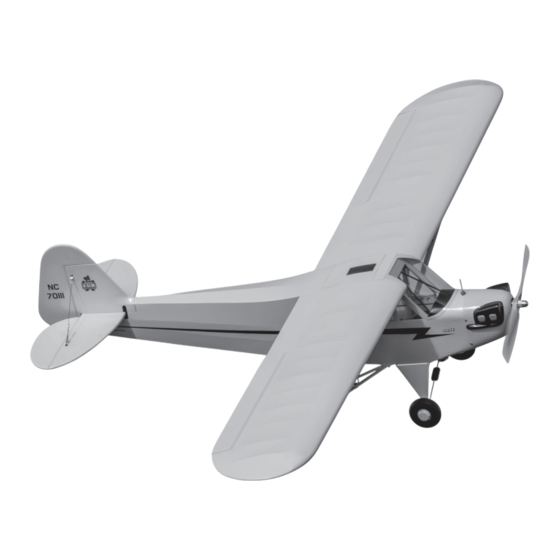
J-3 Cub 10cc
Scan the QR code and select the Manuals and Support quick links from the product
page for the most up-to-date manual information.
Scannen Sie den QR-Code und wählen Sie auf der Produktseite die Quicklinks
Handbücher und Unterstützung, um die aktuellsten Informationen zu Handbücher.
Scannez le code QR et sélectionnez les liens rapides Manuals and Support sur la
page du produit pour obtenir les informations les plus récentes sur le manuel.
Scannerizzare il codice QR e selezionare i Link veloci Manuali e Supporto dalla
pagina del prodotto per le informazioni manuali più aggiornate.
HAN5005
HAN5175
Instruction Manual
Bedienungsanleitung
Manuel d'utilisation
Manuale di Istruzioni
Created 08/2024
680332
Advertisement
Table of Contents

Subscribe to Our Youtube Channel
Related Manuals for Horizon Hobby Hangar 9 J-3 Cub 10cc EP PNP


Summary of Contents for Horizon Hobby Hangar 9 J-3 Cub 10cc EP PNP
- Page 1 J-3 Cub 10cc Instruction Manual Bedienungsanleitung Manuel d’utilisation Manuale di Istruzioni Scan the QR code and select the Manuals and Support quick links from the product page for the most up-to-date manual information. Scannen Sie den QR-Code und wählen Sie auf der Produktseite die Quicklinks Handbücher und Unterstützung, um die aktuellsten Informationen zu Handbücher.
-
Page 2: Notice
Horizon Hobby, LLC. This manual contains instructions for safety, operation and maintenance. It is essential to read and follow all the instructions and warnings in the manual, prior to assembly, setup or use, in order to operate IMPORTANT FEDERAL AVIATION ADMINISTRATION (FAA) INFORMATION correctly and avoid damage or serious injury. -
Page 3: Table Of Contents
TABLE OF CONTENTS REPLACEMENT PARTS Notice ..................................2 Item # Description Meaning of Special Language ..........................2 HAN500501 Fuselage; ARF: J-3 Cub 10cc Safety Warnings and Precautions ..........................2 HAN500502 Wing; LH: J-3 Cub 10cc Safe Operating Recommendations ...........................2 HAN500503 Wing; RH: J-3 Cub 10cc Before Starting Assembly ............................2 Important Federal Aviation Administration (FAA) Information ..................2 HAN500504... -
Page 4: Required For Completion, Glow Engine Installation (Arf)
REQUIRED FOR COMPLETION, GLOW ENGINE INSTALLATION (ARF) TOOLS REQUIRED # Required Item # Description Description SAIE062B FA-62B AAC with Muffl er: BX Box or open end wrench: 10mm, 7/16-inch, 1/2-inch Light machine oil SPM-1032 AR637T+ DSMX 6-Channel AS3X+ & SAFE Telemetry Receiver Clamps Low tack tape SPMSA6380... -
Page 5: Removing Wrinkles
REMOVING WRINKLES AILERON HINGING The covering of your model may develop wrinkles during shipping. Use a sealing iron (HAN1017) with a sealing iron Use a felt-tipped pen to mark the center of the slot in the sock (HAN1018) to remove them. Start with a lower heat setting and use caution while working around areas where hinges on both the wing and control surface. -
Page 6: Aileron Servo Installation
Fit the hinge in the hinge slot. Align the slot in the hinge with Apply several drops of thin CA to each of the hinges, both on the hole in the wing. the top and bottom of the hinge. Do not use accelerator. The CA must be allowed to wick into the hinge to provide the best bond between the hinge and surrounding wood. - Page 7 11. Apply 1–2 drops of thin CA in each hole to harden the 16. Thread a servo mounting screw into each hole, then remove surrounding wood. Allow the CA to fully cure before all the screws. proceeding. 12. Secure the control horn to the aileron using three M2 x 10mm 17.
- Page 8 21. When attaching the linkage to the servo arm, use the hole 26. Guide the servo lead for the aileron through the wing to the that is 5/8 inch (16mm) from the center of the servo horn. wing root. This hole will need to be enlarged using a pin vise and 5/64- inch (2mm) drill bit.
- Page 9 31. Attach the clevis to the outer hole of the aileron control horn. 36. Check the alignment between the wing and aileron. Adjust the clevis if necessary so they are aligned. 32. Use a felt-tipped pen to mark the linkage where it crossed the 37.
-
Page 10: Wing Strut Installation
WING STRUT INSTALLATION 41. Attach the strut fi tting near the aileron to the bottom of the wing using four M3 x 12 socket head cap screws and four M3 lock washers. Apply a drop of threadlock on each screw before tightening them using a 2.5mm hex wrench. -
Page 11: Elevator Installation
48. Slide the wing tube into the wing tube socket. 53. The jury strut ends will fi t into the holes in the underside of the wing. 49. Remove the windshield hatch from the fuselage. It is secured 54. Adjust the strut end so the hole in the strut end aligns with quite fi... - Page 12 58. Place the stabilizer on the fuselage. Center the stabilizer on 62. Use a ruler and carefully cut the covering 1/8 inch (3 mm) the fuselage. inside the line drawn on the stabilizer to remove the covering from the center of the stabilizer. Remove the top and bottom ...
- Page 13 67. Use a toothpick or hobby knife to puncture the covering so 72. Place a T-pin in the center of each hinge. This will keep the the control horn mounting screws can be installed. hinges centered when they are installed. Insert the hinges in the elevator 68.
-
Page 14: Rudder Installation
77. Remove the clear packaging (or waxed paper). Use a hobby 81. Use the technique outlined for the elevator joiner wire knife to remove any excess epoxy if necessary. to prepare and glue the tail gear wire into position using 5-minute epoxy. -
Page 15: Tail Rigging
TAIL RIGGING 91. Slide the cable through the hole in the fi tting 86. Bend each of the aluminum cable tabs slightly using pliers. 87. Slide an M3 x 14mm machine screw through the pre-bent 92. Pass the cable back through the sleeve. Use crimping pliers aluminum cable tab. -
Page 16: Landing Gear Installation
96. Install the remaining rigging to complete the tail installation. 99. Slide the wheel pant, then a wheel collar, onto the axle. 100. Slide the wheel on the axle. The assembly can then be slid fully onto the axle. LANDING GEAR INSTALLATION 101. -
Page 17: Rudder And Elevator Servo Installation
103. Use a fi le to make two 1/2-inch (13mm) wide fl at areas on 108. Slide the inside wheel collar against the wheel and tighten the bottom of the axle. The fi rst area is near the gear, and the the setscrew. - Page 18 113. Center the servos using the radio system. Place the servo 118. Use a felt-tipped pen to mark the pushrod wire where it arm on the servos so they are 90-degrees to the servo center crosses the servo arm. line. Remove any arms that may interfere with the operation of the linkages.
-
Page 19: Windshield Preparation
124. Use a hobby knife to remove the covering for the fuel cap. WINDSHIELD PREPARATION 125. Fit the fuel cap into position. 123. Use medium CA to glue the windshield supports into position. The following photos show the positioning of the supports. ELECTRIC MOTOR INSTALLATION ... -
Page 20: Engine Installation
133. Position the engine in the mounts so the drive washer is 4 inches (117mm) forward of the fi rewall. Use a clamp to hold the engine in position. 129. Attach the motor to the motor box using four 3mm washers 134. - Page 21 138. Use four M3 x 30mm machine screws to attach the engine to 142. With the throttle stick and trim still centered, pass the throttle the mount. The M3 washers and M3 lock nuts are installed pushrod through the connector, then place the servo arm on on the engine mount side during the engine installation.
-
Page 22: Cowling Installation
The engine may need to be removed for the following step. 150. Slide the cowling into position. Use the template to trace the location for the valve cover on the cowling. The engine can be reinstalled once the step has been completed. -
Page 23: Window Installation
155. The dummy engine can be attached to the cowling using EMPENNAGE INSTALLATION silicone adhesive. Trim the dummy engine as necessary 159. Remove the M3 lock nut and M3 washer from the threaded to clear any parts of the engine that may interfere with its rods installed in the fi... -
Page 24: Wing Installation
164. Slide an M3 x 14mm socket head screw through the pre-bent 169. Attach the clevis to the elevator control horn. Slide the clevis aluminum cable tab. Slide the screw through the hole in the retainer over the forks of the clevis. top side of the stabilizer. - Page 25 173. Fit the fuel cap into position. 177. The jury strut ends will fi t into the holes in the underside of the wing. 174. The top hatch has an internal spring-loaded latch. Release 178. Adjust the strut end so the hole in the strut end aligns with the hatch by pulling the latch forward, then pushing upwards.
-
Page 26: Landing Gear Installation
186. Slide a wheel collar on the axle. Tighten the setscrew so the wheel collar is fl ush with the end of the axle. LANDING GEAR INSTALLATION 187. Slide the inside wheel collar against the wheel and tighten the setscrew. Make sure the wheel; can rotate freely. 182. -
Page 27: Battery And Receiver Installation
BATTERY AND RECEIVER INSTALLATION 196. Three struts are installed in the rear bracket. From front to back these are; diagonal strut, rear strut with bushing, 191. Place the battery in the fuselage, and use the hook and spreader bar. loop strap to secure the battery. Make sure not to cover any warning labels on the battery. -
Page 28: Decal Installation
200. Locate the four holes for the landing gear straps on the CENTER OF GRAVITY bottom of the fuselage. Use a hobby knife and #11 blade to expose the holes. Secure the rear strut using two landing CAUTION: You must adjust your aircraft’s center of gear straps and four M3 x 10 sheet metal screws. -
Page 29: Control Throws
(iii) Right inch (60 mm) modifi cation of or to any part of the Product, (iv) attempted service by anyone other than a Horizon Hobby authorized Rudder Left... -
Page 30: Warranty And Service Contact Information
Horizon, you will be asked to provide your complete name, street address, email address and phone number Sales: Horizon Hobby GmbH +49 (0) 4121 2655 100 where you can be reached during business hours. When sending product into Horizon, please include your RMA number, a list of the included items, and a brief summary of the problem. -
Page 31: Academy Of Model Aeronautics National Model Aircraft Safety Code
ACADEMY OF MODEL AERONAUTICS NATIONAL MODEL AIRCRAFT SAFETY CODE BUILDING AND FLYING NOTES Effective January 1, 2018 A model aircraft is a non-human-carrying device capable of sustained fl ight within visual line of sight of the pilot or spotter(s). It may not exceed limitations of this code and is intended exclusively for sport, recreation, education and/or competition. - Page 32 SPECIFICATIONS • SPEZIFIKATIONEN • SPÉCIFICATIONS • SPECIFICHE 82.5 inches 82.5 in (2096 mm) 2096 mm 56 in (1422 mm) 9.6 lbs (4341 g) • 4-Stroke glow: 0.62 cu. in. (10.16 cc) • 4-Stroke gas: 0.66 cu. in. (10.88cc) • 4-Takt Verbrenner: 0,62 cu. in. (10,16 cc) •...
- Page 33 © 2024 Horizon Hobby, LLC. Hangar 9, Sky, AS3X, Avian, IC5, and the Horizon Hobby logo are trademarks or registered trademarks of Horizon Hobby, LLC. The Spektrum trademark is used with permission of Bachmann Industries, Inc. All other trademarks, service marks and logos are the property of their respective owners.
Need help?
Do you have a question about the Hangar 9 J-3 Cub 10cc EP PNP and is the answer not in the manual?
Questions and answers