BIXOLON SRP-350III, SRP-352III, SRP-350IIICOG Manual
- Command manual (121 pages) ,
- User manual (37 pages) ,
- Installation manual (8 pages)
Advertisement
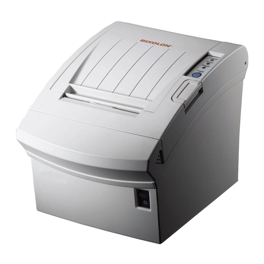
Introduction
SRP-350/352III Series Printers are designed for use with electronic instruments such as system ECR (Electronic Cash Register), POS (Point Of Sales), computer peripheral equipment, etc.
The main features of the printer are as follows:
- Print at a max. speed of 250mm/s
- Low noise thermal printing
- USB (embedded), serial, parallel, and Ethernet ports supported
- Data buffer embedded (allowing receiving of print data even during printing)
- Control of external devices such as cash drawer by peripheral units drive circuit
- Bar code printing
- Different print densities (through switches)
Please be sure to read the instructions in this manual carefully before using your new printer.
※Please use reliable original supplies!
We do not guarantee the quality and AS for any damage to the printer by using fake supplies (or recycled ones).
We at Bixolon Co., Ltd. constantly strive to improve product functions and quality. To do this, the specifications of our product and the contents of the manual may change without prior notice.
Setting up Printer
Unpacking
Your printer box should include these items. If any items are damaged or missing, please contact your dealer for assistance.

Connecting the Cables
You can connect the host computer to the printer by using the interface cable fit for the specifications of the printer and the host computer (POS/ECR). You must use the drawer fit for the specifications of the printer.

Before connecting any of the cables, make sure that both the printer and the host are turned off.
USB Cable

| No. | Signal Name | Designation (Color) | Function |
| Shell | Shield | Drain Cable | Frame Ground |
| 1 | VBUS | RED | Host Power |
| 2 | D- | WHITE | Data Line (D-) |
| 3 | D+ | GREEN | Data Line (D+) |
| 4 | GND | BLACK | Signal Ground |
Serial Cable(RS-232C)
Single Interface


Dual Interface

| Pin No. | Signal Name | Direction | Function |
| Main | Frame GND | - | Frame Ground |
| 2 | TXD | Output | Data Transmission |
| 3 | RXD | Input | Data Reception |
| 6 | DSR | Input | This signal shows whether the host computer can receive data (hardware flow control).
|
| 7 | Signal GND | - | Signal Ground |
| 20 | DTR | Output | This signal shows whether the printer works or not (hardware flow control).
|
| Shield | Frame GND | - | Frame Ground |
Parallel Cable(IEEE1284)

| Pin No. | Source | Compatibility Mode | Nibble Mode |
| 1 | Host | nStrobe | HostClk |
| 2 | Host/Printer | Data 0 (LSB) | - |
| 3 | Host/Printer | Data 1 | - |
| 4 | Host/Printer | Data 2 | - |
| 5 | Host/Printer | Data 3 | - |
| 6 | Host/Printer | Data 4 | - |
| 7 | Host/Printer | Data 5 | - |
| 8 | Host/Printer | Data 6 | - |
| 9 | Host/Printer | Data 7 (MSB) | - |
| 10 | Printer | Nack | PtrClk |
| 11 | Printer | Busy | PtrBusy /Data3,7 |
| 12 | Printer | Perror | AckDataReq/Data2,6 |
| 13 | Printer | Select | Xflag/Data1,5 |
| 14 | Host | nAutoFd | HostBusy |
| 15 | - | NC | NC |
| 16 | - | GND | GND |
| 17 | - | FG | FG |
| 18 | Printer | Logic-H | Logic-H |
| 19~30 | - | GND | GND |
| 31 | Host | nInit | nInit |
| 32 | Printer | nFault | nDataAvail/Data0,4 |
| 33 | - | GND | ND |
| 34 | Printer | DK_Status | ND |
| 35 | Printer | +5V | ND |
| 36 | Host | nSelectIn | 1284-Active |
Ethernet Cable

| Pin No. | Signal Name | Color | Function |
| 1 | TD+ | White Orange | Transmit + |
| 2 | TD- | Orange | Transmit - |
| 3 | TCT | White Green | Receive + |
| 4 | NC | Blue | |
| 5 | NC | White Blue | |
| 6 | RCT | Green | Receive - |
| 7 | RD+ | White Brown | |
| 8 | RD- | Brown |
* For more detailed information, please refer to User Manual for Ethernet on our website.
Connecting Drawer

Connect the cash drawer connecting cable to the cash drawer connection in the rear of the printer.

Use a cash drawer fit for printer specifications.
Using an improper cash drawer may cause faults in the cash drawer and the printer.
Do not connect a telephone line to the drawer kick-out connector.
Otherwise, the telephone line and the computer may be damaged.
| Pin No. | Signal Name | Direction |
| 1 | Frame Ground | - |
| 2 | Drawer Kick-out Drive Signal 1 | Output |
| 3 | Drawer Open/Close Signal | Input |
| 4 | +24V | - |
| 5 | Drawer Kick-out Drive Signal 2 | Output |
| 6 | Signal Ground | - |
Setting Dip Switches
Serial Interface
- DIP Switch 1
| SW | Function | ON | OFF | Default |
| 1-1 | Auto Line Feed | Enabled | Disabled | OFF |
| 1-2 | Flow Control | XON/XOFF | DTR/DSR | OFF |
| 1-3 | Data Length | 7-bit | 8-bit | OFF |
| 1-4 | Parity Check | Yes | No | OFF |
| 1-5 | Parity Selection | EVEN | ODD | OFF |
| 1-6 | Baud Rate Selection (bps) | Refer to the following Table 1 | OFF | |
| 1-7 | ON | |||
| 1-8 | OFF | |||
- DIP Switch 2
| SW | Function | ON | OFF | Default |
| 2-1 | Reserved | - | - | OFF |
| 2-2 | Reserved | - | - | OFF |
| 2-3 | Internal Bell Control | Disabled | Enabled | OFF |
| 2-4 | Auto Cutter Selection | Disabled | Enabled | OFF |
| 2-5 | Printing Density | Refer to the following Table 2 | OFF | |
| 2-6 | OFF | |||
| 2-7 | Near End Sensor Control | Disabled | Enabled | OFF |
| 2-8 | Auto External Buzz | Enabled | Disabled | OFF |
Parallel & USB & Ethernet Interface
- DIP Switch 1
| SW | Function | ON | OFF | Default |
| 1-1 | Auto Line Feed | Enabled | Disabled | OFF |
| 1-2 | Reserved | - | - | OFF |
| 1-3 | Reserved | - | - | OFF |
| 1-4 | Reserved | - | - | OFF |
| 1-5 | Reserved | - | - | OFF |
| 1-6 | Reserved | - | - | OFF |
| 1-7 | Reserved | - | - | ON |
| 1-8 | Reserved | - | - | OFF |
- DIP Switch 2
| SW | Function | ON | OFF | Default |
| 2-1 | Reserved | - | - | OFF |
| 2-2 | Reserved | - | - | OFF |
| 2-3 | Internal Bell Control | Disabled | Enabled | OFF |
| 2-4 | Auto Cutter Selection | Disabled | Enabled | OFF |
| 2-5 | Printing Density | Refer to the following Table 2 | OFF | |
| 2-6 | OFF | |||
| 2-7 | Near End Sensor Control | Disabled | Enabled | OFF |
| 2-8 | Auto External Buzz | Enabled | Disabled | OFF |
- Table 1 – Baud rate (bps) Selection
| Transmission Speed | 1-6 | 1-7 | 1-8 | Default |
| 2400 | ON | OFF | OFF | 9600 |
| 4800 | ON | OFF | ON | |
| 9600 | OFF | ON | OFF | |
| 19200 | OFF | OFF | OFF | |
| 38400 | OFF | ON | ON | |
| 57600 | OFF | OFF | ON | |
| 115200 | ON | ON | ON |
- Table 2 – Print Density Selection
| Printing Density | 2-5 | 2-6 | Default |
| Level 1 | OFF | OFF |
|
| Level 2 | ON | OFF | |
| Level 3 | OFF | ON | |
| Level 4 | ON | ON |
 Attention
The printer must be turned off when changing the DIP switch settings. Failure to turn it off may cause a short circuit and damage the printer.
To change the settings:
- Turn off the printer.
- Open the DIP switch cover located at the back of the printer.
- Set the DIP switch number.
- Close the DIP switch cover after the settings have been completed.
- Position the printer in front and turn it on.
Note
Please make sure that the printer is turned off when changing the DIP switch settings. The change is not accepted when the power is on.
Installing & Replacing Paper
Be sure to use paper rolls that meet the specifications. Do not use paper rolls that have the paper glued to the core because the printer cannot detect the paper end correctly.
- Make sure that the printer is not receiving data; otherwise, data may be lost.
- Open the paper roll cover by pressing the Cover-Open button.
![]()
Do not open the print cover while the printer is operating. This may damage the printer.
![]()
- Remove the used paper roll core if there is one.
- Insert the paper roll as shown.
![]()
- Be sure to note the correct direction that the paper comes off the roll.

- Pull out a small amount of paper, as shown. Then close the cover.
![]()
When closing the cover, press the center of printer cover firmly to prevent paper misloading.

- Tear off the paper as shown.


Recommended Papers
- TF50KS-E (Paper Thickness: 65μm): Nippon Paper Industries Co., Ltd.
- PD 160R (Paper Thickness: 75μm): New Oji Paper Mfg. Co., Ltd.
- P350 (Paper Thickness: 62μm): Kansaki Specialty Paper, Inc. (USA)
Use of papers other than those recommended above may damage TPH or degrade the printing quality and our company is not responsible for the damage caused by nonrecommended papers. If you have to use other products, we recommend that you use papers with a similar level of quality to the recommended ones.
Structure of 2 inches specification
NOTE
This setting can be changed from VMSM Utility.
The changes for 2 inches specification should be applied to the following components as well..

Removing Paper Jam

- When a paper jam occurs, turn the printer off and then back on, open the cover and remove the jammed paper.
In case of a slight jam, it is possible to return the operating blade to the original position and open the cover only by turning the printer off and then back on.
Despite the operation, if the cover is not open, take the following action: - Turn the printer off.
- Press both sides of the cover-cutter to separate as shown in the figure below.
- Turn the knob and insert the projected blade by using a cross-tip screwdriver as shown below.
- Press the Cover-Open button, open the cover, remove the jammed paper and assemble the separated COVER-CUTTER.
- Turn the printer on to use.
Using Printer Functions
Control Panel

 POWER
POWER
When turning on the power, a green LED will be lit.
ERROR
When an error occurs, a red LED will be lit. (e.g. no paper, cover ajar, etc.)
PAPER
Red LED will be lit when the paper roll is running low. The LED blinks when the printer is in self-test standby mode or macro execution standby mode.
FEED
Press the FEED button once to discharge extra paper. Holding down the FEED button will discharge paper continuously until the button is released.
Connecting a Computer
Please connect a computer by using the cable provided.
- Plug the cable connector securely into the printer's interface connector.
- Tighten the screws on the cable connector.
![]()
- Attach the other end of the parallel cable to the computer.

Connecting Power Supply
When connecting or disconnecting the power supply from the printer, make sure that the power supply is not plugged into an electrical outlet. Otherwise you may damage the power supply or the printer.
If the power supply's rated voltage and your outlet's voltage do not match, contact your dealer for assistance. Do not plug in the power cord. Otherwise, you may damage the power supply or the printer.
- Make sure that the printer's power switch is turned off, and the power supply's power cord is unplugged from the electrical outlet.
- Check the label on the power supply to make sure that the voltage required by the power supply matches that of your electrical outlet.
- Plug in the power supply's cable as shown below. Notice that the flat side of the plug faces down.
![]()

To remove the power cord, grasp the connector at the arrow and pull it straight out.
Self-Test
The self-test checks whether the printer has any problems. If the printer does not function properly, contact your dealer. The self-test checks the following:
- Make sure paper roll has been installed properly.
- Turn on the power while holding down the FEED button. The self-test begins.
- The self-test prints the current printer status, which provides the control ROM version and the DIP switch setting.
- After printing the current printer status, print the phrase as shown below and stop (The paper signal light flickers).
SELF-TEST PRINTING.
PLEASE PRESS THE FEED BUTTON. - Press the FEED button to continue printing. The printer prints a form using the built-in character set
- The self-test automatically ends and cuts the paper after printing the phrase as shown below.
*** COMPLETED *** - The printer is ready to receive data as soon as it completes the self-test.
Hexadecimal Dumping
This function allows experienced users to see exactly what data is coming to the printer. This can be useful in finding software problems. When you turn on the hexadecimal dump function, the printer prints all commands and data in hexadecimal format along with a guide section to help you find specific commands
To use the hexadecimal dump function, follow these steps.
- After you make sure that the printer is off, open the cover.
- Turn the printer on, while holding down the FEED button.
- Close the cover, and then the printer enters the hexadecimal dump mode.
- Select the hexadecimal printing function in the mode selection menu to move to the hexadecimal printing mode.
- Run any software program that sends data to the printer.
The printer will print all the codes it receives in a two-column format.
The first column contains the hexadecimal codes and the second column gives the ASCII characters that correspond to the codes.
1B 21 00 1B 26 02 40 40 40 40. ! . . &. @ @ @ @
02 0D 1B 44 0A 14 1E 28 28 28. . . D. . . . ( ( (
00 01 0A 41 0D 42 0A 43 43 43. . . A. B. C C C- A period (.) is printed for each code that has no ASCII equivalent.
- During the hex dump, all commands except DLE EOT and DLE ENQ are disabled.
- When the printing finishes, turn off the printer.
- Turn on the printer and then the hexadecimal mode is off.
Specifications
| Printing Method | Thermal transfer printing | |||
| Dot Density | SRP-350III: 180 dpi (7dots/mm) | |||
| SRP-352III: 203 dpi (8dots/mm) | ||||
| Printing Width | 3 inches | 72 mm | ||
| 2 inches | 48 mm | |||
| Roll Width | 3 inches | 79.5±0.5 mm | ||
| 2 inches | 57.5±0.5 mm | |||
| No. of Characters per Line (Default Value) | SRP-350III : 42 (Font A),56 (Font B), 56 (Font C) SRP-352III : 48 (Font A),64 (Font B), 64 (Font C) | |||
| Printing Speed | Max. 250 mm/sec | |||
| Receiving Buffer Size | 4K bytes | |||
| Printing speed may be slightly slow depending on the data transmission speed and the combination of commands. | ||||
| Supply Voltage | SMPS Input Voltage | 100~240 VAC | ||
| Frequency | 50/60 Hz | |||
| SMPS Output Voltage | 24 VDC | |||
| Environment Condition | Temperature | Operating: 0 ~ 40 ℃ Storage: -20 ~ 60 ℃ | ||
| Humidity | Operating: 10 ~ 80% RH Storage: 10 ~ 90% RH Paper excluded | |||
| Life Span | Mechanism Header *) | 150 Km | ||
| Auto Cutter | 1,800,000 cuts | |||
| MCBF | Mechanism *) | 70,000,000 lines | ||
*) The specifications were determined based on operation at normal temperature using designated paper on default settings. They are subject to change depending on temperature or printing level.
*) The specifications were tested according to standard reliability. If you want to test the product to determine its life cycle, please contact us for more details and comply with the standard reliability for testing.
* These values may vary with environment temperature, printing level, etc.
* The switch is the disconnecting device. Turn off switch from any hazard.
Cleaning Printer
Paper dust inside the printer may lower the print quality. In this case clean the printer as follows:
- Open the printer cover and remove any paper.
- Clean the print head with a cotton swab moistened with alcohol solvent.
- Clean the paper sensor and paper roller with a cotton swab and a dry cloth.
- Insert a paper roll and close the printer cover.
The remaining amount of paper detected by paper near-end sensor varies with the diameter of the paper core. To set the paper near-end sensor, contact your dealer.
Use of Wall Mount
When the wall mount is used, please use by setting DIP Switch 2, 2-7 ON (disabled) because the paper near-end sensor does not work properly.
http://www.bixolon.com
Safety Precautions
In using the present appliance, please keep the following safety regulations in order to prevent any hazard or material damage.
Violating following instructions can cause serious injury or death.
Do not plug several products in one multi-outlet.

- This can provoke over-heating and a fire.
- If the plug is wet or dirty, dry or wipe it before usage.
- If the plug does not fit perfectly with the outlet, do not plug in.
- Be sure to use only standardized multi-outlets.
Do not pull the cable to unplug.
- This can damage the cable, which is the origin of a fire or a breakdown of the printer.
![]()

Do not plug in or unplug with your hands wet.
- You can be electrocuted.
![]()

You must use only the supplied adapter.
- It is dangerous to use other adapters.
![]()

Keep the plastic bag out of children's reach.
- If not, a child may put the bag on his head.
![]()

Do not bend the cable by force or leave it under any heavy object.
- A damaged cable can cause a fire.
![]()

Violating following instructions can cause slight wound or damage the appliance.
If you observe a strange smoke, odor or noise from the printer, unplug it before taking following measures.

- Switch off the printer and unplug the set from the mains.
- After the disappearance of the smoke, call your dealer to repair it.
Install the printer on the stable surface.
- If the printer falls down, it can be broken and you can hurt yourself.
![]()

Do not let water or other foreign objects in the printer.
- If this happened, switch off and unplug the printer before calling your dealer.
![]()

Keep the desiccant out of children's reach.
- If not, they may eat it.
![]()

Use only approved accessories and do not try to disassemble, repair or remodel it for yourself.

- Call your dealer when you need these services.
- Do not touch the blade of auto cutter.
Do not use the printer when it is out of order. This can cause a fire or an electrocution.
- Switch off and unplug the printer before calling your dealer.
![]()

Some semiconductor devices are easily damaged by static electricity. You should turn the printer "OFF", before you connect or remove the cables on the rear side, in order to guard the printer against the static electricity. If the printer is damaged by the static electricity, you should turn the printer "OFF".
Rating Label Symbol Information

DC (Direct current)
Label Material
- Control Label: PC
- Other Labels: PET
Documents / Resources
References
Download manual
Here you can download full pdf version of manual, it may contain additional safety instructions, warranty information, FCC rules, etc.
Download BIXOLON SRP-350III, SRP-352III, SRP-350IIICOG Manual
Advertisement


Need help?
Do you have a question about the SRP-350III and is the answer not in the manual?
Questions and answers