Kostal INVEOR MP Operating Manual
Hide thumbs
Also See for INVEOR MP:
- Short manual (4 pages) ,
- Operating manual (51 pages) ,
- Short manual (15 pages)
Advertisement
Quick Links
Advertisement

Related Manuals for Kostal INVEOR MP


Summary of Contents for Kostal INVEOR MP
- Page 1 Operating manual INVEOR MP...
- Page 2 This manual may not be reproduced, stored, transmitted or translated in any form or by means of any medium - in whole or in part - without prior written permission. Operating manual for INVEOR MP | DOC02399128-0008 | 2022-06 | V1.80 EN...
- Page 3 3.3.3 Basic connection versions ........18 Delta connection variant, sizes B-C ...... 19 Delta connection variant, sizes B-C ...... 20 3.3.4 Short circuit and ground protection ....... 20 Operating manual for INVEOR MP | DOC02399128-0008 | 2022-06 | V1.80 EN...
- Page 4 5.4.2 Motor data ............99 5.4.3 I t ................ 101 Index ..............136 5.4.4 Switching frequency ..........103 5.4.5 Controller data ............ 104 5.4.6 Quadratic characteristic curve ......107 Operating manual for INVEOR MP | DOC02399128-0008 | 2022-06 | V1.80 EN...
- Page 5 De-energise drive controller and secure it against being restarted. Fig. 1: Structure of the warnings Warning symbol Signal word Type of danger and its source Possible consequence(s) of failure to comply Corrective actions Operating manual for INVEOR MP | DOC02399128-0008 | 2022-06 | V1.80 EN...
- Page 6 Item Chapter IMPORTANT INFORMATION The drive controller may only be assembled, operated, maintained and installed by trained and qualified staff. Fig. 2: Example of an information note Operating manual for INVEOR MP | DOC02399128-0008 | 2022-06 | V1.80 EN...
- Page 7 Using drive controllers in equipment that is not with. fixed is considered as an exceptional environmental condition and is only permitted if allowed by the standards and guidelines applicable on site. Operating manual for INVEOR MP | DOC02399128-0008 | 2022-06 | V1.80 EN...
- Page 8 (relating to the making available on the market of radio equipment and repealing Directive 1999/5/EC) You will find a detailed EU Declaration of Conformity at: www.kostal-industrie- elektrik.com/downloads/downloadmanager#Antriebstechn Operating manual for INVEOR MP | DOC02399128-0008 | 2022-06 | V1.80 EN...
- Page 9 Risk of burns from hot surfaces! Serious burns to the skin from hot surfaces! Allow the drive controller's cooling elements to cool sufficiently. Operating manual for INVEOR MP | DOC02399128-0008 | 2022-06 | V1.80 EN...
- Page 10 The drive controller must not be used as parts! "Emergency stop equipment" (see DIN EN 60204-1; VDE 0113-1:2007-06). Death or serious injury! De-energise drive controller and secure it against being restarted. Operating manual for INVEOR MP | DOC02399128-0008 | 2022-06 | V1.80 EN...
- Page 11 Measurement of insulation resistance on power Death or serious injury! stack De-energise drive controller and secure it The power stack of an INVEOR MP is tested with 2.02 kV against being restarted. in the course of series testing. Danger due to electrical shock and Should the insulation resistance have to be measured discharge.
- Page 12 Main switch, MMI option Optional module OA00 No option module OA10 Main switch Customer CO00 KOSTAL INVEOR INV MP V S01 IVxx PWxx LPxx APxx GHxx DKxx OAxx COxx Operating manual for INVEOR MP | DOC02399128-0008 | 2022-06 | V1.80 EN...
- Page 13 OA00 No option module OA10 Main switch OA30 Brake module Customer CO00 KOSTAL INVEOR MP (standard) INV MP V S01 IVxx PWxx LPxx APxx GHxx DKxx OAxx COxx Operating manual for INVEOR MP | DOC02399128-0008 | 2022-06 | V1.80 EN...
- Page 14 (not part of the scope of delivery) Seal (not part of the scope of delivery) Adapter plate article number Motor (not part of the scope of delivery) Operating manual Operating manual for INVEOR MP | DOC02399128-0008 | 2022-06 | V1.80 EN...
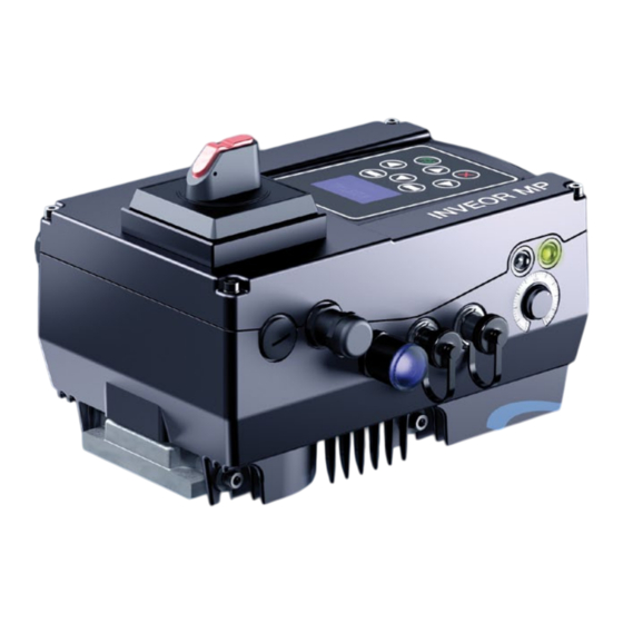
- Page 15 2.4 Description of INVEOR MP drive controller The INVEOR MP drive controller is a device for controlling the speed of three-phase AC motors. The drive controller can be integrated in the motor (with the standard adapter plate) or fitted close to the motor (with the wall mounting adapter plate).
- Page 16 The cross-section of the supply line must be designed according to the transfer category and maximum permitted current. The contractor commissioning the device must ensure protection for the power line. Operating manual for INVEOR MP | DOC02399128-0008 | 2022-06 | V1.80 EN...
- Page 17 Mounting points and sealing surfaces must be kept free of compatibility of the intended paint. paint for purposes of EMC and grounding! Operating manual for INVEOR MP | DOC02399128-0008 | 2022-06 | V1.80 EN...
- Page 18 Fig. 11: Star or delta connection, size A DANGER! Risk of death due to electrical shock! Death or serious injury! De-energise drive controller and secure it against being restarted. Operating manual for INVEOR MP | DOC02399128-0008 | 2022-06 | V1.80 EN...
- Page 19 Risk of death due to electrical shock! Regularly check that the nuts (1) are secure! Death or serious injury! De-energise drive controller and secure it against being restarted. Operating manual for INVEOR MP | DOC02399128-0008 | 2022-06 | V1.80 EN...
- Page 20 DAMAGE TO PROPERTY POSSIBLE Risk of damage to the drive controller. Correct phase assignment must be observed when connecting the drive controller, otherwise the motor may be overloaded. Operating manual for INVEOR MP | DOC02399128-0008 | 2022-06 | V1.80 EN...
- Page 21 2 conductors of the same cross-section, flexible with TWIN-AEH 0.25 mm² 1.5 mm² with plastic sleeve AWG/kcmil conductor cross-section according to UL/CUL Length of stripped insulation: 15 mm Mounting temperature: -5°C to +100°C Operating manual for INVEOR MP | DOC02399128-0008 | 2022-06 | V1.80 EN...
- Page 22 4 mm² min. 0.5 mm² 2 conductors of the same cross-section, flexible with TWIN-AEH with plastic sleeve max. 6 mm² min. 20 AWG according to UL/CUL max. 2 Operating manual for INVEOR MP | DOC02399128-0008 | 2022-06 | V1.80 EN...
- Page 23 You can order individually modified adapter plates from KOSTAL for selected motors. DAMAGE TO PROPERTY POSSIBLE Be careful not to damage the seal. Operating manual for INVEOR MP | DOC02399128-0008 | 2022-06 | V1.80 EN...
- Page 24 If spring elements (5) are not used when assembling the adapter plate, there must be an extra connection between the motor and drive controller to produce a correct protective conductor connection. Operating manual for INVEOR MP | DOC02399128-0008 | 2022-06 | V1.80 EN...
- Page 25 10. Plug the drive controller (3) onto the adapter plate (4) Only motor PTCs corresponding to DIN 44081/44082 and secure uniformly using the four lateral bolts (5) may be connected! (sizes A - C) (torque: 4.0 Nm). Operating manual for INVEOR MP | DOC02399128-0008 | 2022-06 | V1.80 EN...
- Page 26 Screw adapter plate (2) and seal (1) on to motor with Screw cups (7) onto adapter plate (2) with four four retaining bolts (3) and spring elements (4). retaining bolts (8) and spring elements (9) (torque 8.5 Nm). Operating manual for INVEOR MP | DOC02399128-0008 | 2022-06 | V1.80 EN...
- Page 27 (3) into housing of drive controller. seal (10) sits perfectly and is not damaged! 11. Carefully place the drive controller (15) onto the cup (7) of the INVEOR MP. Operating manual for INVEOR MP | DOC02399128-0008 | 2022-06 | V1.80 EN...
- Page 28 DC mains (+) Mains phase 2 Not assigned Mains phase 3 DC mains (-) Protective Protective conductor conductor Tab. 2: AC feed-in X1 Tab. 3: DC input X1 Operating manual for INVEOR MP | DOC02399128-0008 | 2022-06 | V1.80 EN...
- Page 29 Mains phase 2 Mains phase 3 Protective conductor Tab. 4: 3 x 400 V AC terminal assignment X1 The protective conductor must be connected to the "PE" contacts. Operating manual for INVEOR MP | DOC02399128-0008 | 2022-06 | V1.80 EN...
- Page 30 Connection for brake resistor (+) Connection for brake resistor (-) Tab. 7: Optional terminal assignment for brake chopper Fig. 17: Size D Fig. 16: Sizes A - C Operating manual for INVEOR MP | DOC02399128-0008 | 2022-06 | V1.80 EN...
- Page 31 (1). (Torque 4 Nm) Size. Torque A - C 2 Nm (4 x M4 x 28) 4 Nm (4 x M6 x 28) Operating manual for INVEOR MP | DOC02399128-0008 | 2022-06 | V1.80 EN...
- Page 32 A GND (Ground 10 V) Ground A. In 2 Free (not assigned) A GND (ground 10 V) Ground Tab. 7: Terminal assignment X5 of the standard application board Operating manual for INVEOR MP | DOC02399128-0008 | 2022-06 | V1.80 EN...
- Page 33 Normally open relay 2 Normally closed relay 2 Tab. 9: Terminal assignment X7 (relay 2) INFORMATION In the factory setting, “no function” is assigned to relay 2 (parameter 4.210). Operating manual for INVEOR MP | DOC02399128-0008 | 2022-06 | V1.80 EN...
- Page 34 4150 10 V Out For ext. voltage divider 24 V Out Int. power supply 24 V Out Int. power supply En HW (enable) Enable hardware GND (ground) Ground Operating manual for INVEOR MP | DOC02399128-0008 | 2022-06 | V1.80 EN...
- Page 35 The drive controller is ready once a 3 x 400 V AC mains supply has been activated (on terminals L1 to L3) or a DC mains supply has been activated (on terminals L1 and L3). The drive controller can also be started up by connecting an external 24 V voltage. Operating manual for INVEOR MP | DOC02399128-0008 | 2022-06 | V1.80 EN...
- Page 36 Pin male connector Pin female connector Assignment 3.4.7 PHOENIX Quickon connection variant Fig. 22: PHOENIX Quickon Colour Assignment Sw / BK br / BN gr / GY ge / YE Operating manual for INVEOR MP | DOC02399128-0008 | 2022-06 | V1.80 EN...
- Page 37 Fig. 23: Main switch Assignment 3.4.9 Mains supply connection variant with brake module, size A IMPORTANT INFORMATION The brake module's mains supply is wired ex-factory with sizes B - D! Operating manual for INVEOR MP | DOC02399128-0008 | 2022-06 | V1.80 EN...
- Page 38 2 conductors of the same cross-section, flexible with AEH without 0.5 mm² 2.5 mm² plastic sleeve 2 conductors of the same cross-section, flexible with TWIN-AEH with 0.5 mm² 1 mm² plastic sleeve Operating manual for INVEOR MP | DOC02399128-0008 | 2022-06 | V1.80 EN...
- Page 39 Use the three screws (6) to screw unit and housing together (torque 2 Nm). Unscrew the four screws (1) from the drive controller's housing cover (2) and then take it off. Operating manual for INVEOR MP | DOC02399128-0008 | 2022-06 | V1.80 EN...
- Page 40 Connect PE cable (13) of mains feed (10) to “PE” of Death or serious injury! mains terminal [ X1 ] (9). (Torque of mains terminal screw “PE” 2 Nm). De-energise drive controller and secure it against being restarted. Operating manual for INVEOR MP | DOC02399128-0008 | 2022-06 | V1.80 EN...
- Page 41 10.1 EMC limit classes). Only use a shielded cable with the required cross-section. There must be a PE connection (underneath the wall Fig. 24: Minimum clearances mounting's terminal board)! Operating manual for INVEOR MP | DOC02399128-0008 | 2022-06 | V1.80 EN...
- Page 42 To achieve optimum self-convection of the drive controller, ensure that the (EMC) screw connection (5) is facing upwards during installation. If there is no additional ventilation for the INVEOR MP, only vertical installation is permitted. Operating manual for INVEOR MP | DOC02399128-0008 | 2022-06 | V1.80 EN...
- Page 43 Wire the motor cable to contacts U, V, W (and the star point in some cases) in the connection terminal, as described in the "Basic connection versions" chapter. Operating manual for INVEOR MP | DOC02399128-0008 | 2022-06 | V1.80 EN...
- Page 44 (3). The cross-section of the equipotential bonding line must correspond to at least the cross-section of the power cable. Operating manual for INVEOR MP | DOC02399128-0008 | 2022-06 | V1.80 EN...
- Page 45 (7) inserted for delivery for this purpose. When the bridge is in place, the temperature of the motor is not monitored! Only motor PTCs corresponding to DIN 44081/44082 may be connected! Operating manual for INVEOR MP | DOC02399128-0008 | 2022-06 | V1.80 EN...
- Page 46 Ensure that the shielding contact is in order (large surface)! Connect the prescribed PE connection in the motor connection box! Close the motor connection box. Fig. 32: Wiring on the motor connection box Operating manual for INVEOR MP | DOC02399128-0008 | 2022-06 | V1.80 EN...
- Page 47 Mount seal (2), along with cup (3), to the adapter plate (1). IMPORTANT INFORMATION Use the retaining bolts (5) and spring elements (4) Please ensure that the seal (2) sits perfectly! provided (torque 8.5 Nm). Operating manual for INVEOR MP | DOC02399128-0008 | 2022-06 | V1.80 EN...
- Page 48 Fig. 35: Fastening drive controller to size D cup 10. Carefully place the drive controller (9) onto the cup (3) 11. Screw down both parts uniformly with the two M8 screws (10) (torque: max. 25 Nm). Operating manual for INVEOR MP | DOC02399128-0008 | 2022-06 | V1.80 EN...
- Page 49 Tab. 10: 3~ 400 V terminal assignment X1 Terminal no. Designation Assignment DC mains (+) Not assigned DC mains (-) Protective conductor Tab. 11: DC feed 565 V terminal assignment X1 Operating manual for INVEOR MP | DOC02399128-0008 | 2022-06 | V1.80 EN...
- Page 50 Fig. 38: Closing housing size D 16. Place cover (8) on housing of drive controller (9). 17. Screw down both parts with the four screws (7) (torque 4 Nm). Operating manual for INVEOR MP | DOC02399128-0008 | 2022-06 | V1.80 EN...
- Page 51 Non-compliance may result in serious injury. 4.2 Communication The drive controller can be commissioned in the following ways: using the INVERTERpc PC software Fig. 39: PC software – start screen Operating manual for INVEOR MP | DOC02399128-0008 | 2022-06 | V1.80 EN...
- Page 52 Co m m is s io n in g using the INVEOR MMI handheld controller Fig. 40: MMI handheld controller using the MMI* in the cover (MMI option) Fig. 41: MMI option Man-machine interface Operating manual for INVEOR MP | DOC02399128-0008 | 2022-06 | V1.80 EN...
- Page 53 Fig. 43: Bluetooth module M16 (permanently fitted ex factory) Fig. 44: Bluetooth stick M12 (optional accessories) NOTE If using the Bluetooth stick, the password is fixed as 000000. Operating manual for INVEOR MP | DOC02399128-0008 | 2022-06 | V1.80 EN...
- Page 54 Motor current limit rotation Frequency Motor X(-1) Target value control 1.150 1.020 1.021 1.060 1.051 1.050 5.069 1.053 1.052 5.070 5.071 1.054 Fig. 45: General structure of target value generation Operating manual for INVEOR MP | DOC02399128-0008 | 2022-06 | V1.80 EN...
- Page 55 Perform the application settings (ramps, inputs, outputs, target values etc.). Optional: Define an access level (1 - MMI, 2 - user, 3 - manufacturer). See Fig. of block diagram in chapter Quickstart guide Operating manual for INVEOR MP | DOC02399128-0008 | 2022-06 | V1.80 EN...
- Page 56 Co m m is s io n in g 4.4.2 Commissioning using PC, combined with MMI option Install the INVERTERpc software (you can obtain programming software from KOSTAL free of charge. Required operating system: Windows 7 / 10 [32 / 64 bit]).
- Page 57 In the case of PID process control, the inversely. target value and actual value are compared and the system then regulates to a specific process variable. Operating manual for INVEOR MP | DOC02399128-0008 | 2022-06 | V1.80 EN...
- Page 58 Once the actual value deviates from the target value by the set % value, the “PID stand-by hysteresis” (3.071), the control (the motor) is started again. Stand-by function in PID controller Fig. 47: Stand-by function in PID process control Operating manual for INVEOR MP | DOC02399128-0008 | 2022-06 | V1.80 EN...
- Page 59 Fixed frequency 5 40 Hz 2.051 to 2.057 Fixed frequency 6 45 Hz 2.051 to 2.057 Fixed frequency 7 50 Hz Tab. 13: Logic table for fixed frequencies Operating manual for INVEOR MP | DOC02399128-0008 | 2022-06 | V1.80 EN...
- Page 60 200: SynRM efficiency Synchronous motor without Regulated, encoderless Stationary, < 5 min permanent magnets overload capable, down to zero speed, highest efficiency Continues on next page Operating manual for INVEOR MP | DOC02399128-0008 | 2022-06 | V1.80 EN...
- Page 61 "Motor current limit fixed" (5.069). This will result in corresponding torques for a few milliseconds. The resulting jolting movements of the motor shaft and the noises produced are normal! Operating manual for INVEOR MP | DOC02399128-0008 | 2022-06 | V1.80 EN...
- Page 62 . Afterwards, however, the operating characteristics should be checked critically and, if there is an error, the motor identification should be carried out again with blocking. Operating manual for INVEOR MP | DOC02399128-0008 | 2022-06 | V1.80 EN...
- Page 63 Once this time has lapsed, the system always changes over necessary. to the pump with the lowest operating hours. Operating manual for INVEOR MP | DOC02399128-0008 | 2022-06 | V1.80 EN...
- Page 64 M12 connecting cable ( 2 m ) (Article no.:10138812) M12 Y-splitter M12 connecting cable ( 5 m ) (Art. no.: 10138799) (Article no.:10138813) M12 terminating resistor (Article no.:10138793) Operating manual for INVEOR MP | DOC02399128-0008 | 2022-06 | V1.80 EN...
- Page 65 (time-optimal) course to the target X traj setpoint These parameters determine the guidance behaviour of the positioning, i.e. the response to a target value change. Operating manual for INVEOR MP | DOC02399128-0008 | 2022-06 | V1.80 EN...
- Page 66 Change to positioning mode (parameter 1.100) Observe guidance step response and thereby slowly increase or lower Pos. control boost (9.100) until the (subjectively) desired controller hardness is achieved. There should be no overshooting. Operating manual for INVEOR MP | DOC02399128-0008 | 2022-06 | V1.80 EN...
- Page 67 0 = switch drive controller off and on for transfer 1 = at speed of 0 2 = during operation Value range (from – to – factory setting) Other parameters related to this parameter. Operating manual for INVEOR MP | DOC02399128-0008 | 2022-06 | V1.80 EN...
- Page 68 Deceleration time 2 is the time that the drive controller needs to brake to 0 Hz from the max. frequency (1.021). 1.054 If the set deceleration time cannot be reached, the fastest possible deceleration time is implemented. Operating manual for INVEOR MP | DOC02399128-0008 | 2022-06 | V1.80 EN...
- Page 69 Given the application, it is good if the drive starts and stops smoothly. This can be achieved by smoothing the acceleration and delay time. t1 S-curve time (1.060) t2 Run up time (1.051) t3 Deceleration time (1.050) Operating manual for INVEOR MP | DOC02399128-0008 | 2022-06 | V1.80 EN...
- Page 70 6 = motor potentiometer 7 = sum of analogue inputs 1 and 2 8 = PID fixed target values (3.062 to 3.069) 9 = fieldbus 10 = INVEOR soft PLC Operating manual for INVEOR MP | DOC02399128-0008 | 2022-06 | V1.80 EN...
- Page 71 5 = digital input 4 (function active with high signal) 6 = INVEOR soft PLC 7 = analogue input 1 (must be selected in parameter 4.030) 8 = analogue input 2 (must be selected in parameter 4.060) Operating manual for INVEOR MP | DOC02399128-0008 | 2022-06 | V1.80 EN...
- Page 72 In addition to the acknowledge function (1.180), an automatic fault acknowledgement can be selected. = no automatic acknowledgement > 0 = time for automatic resetting of error in seconds Operating manual for INVEOR MP | DOC02399128-0008 | 2022-06 | V1.80 EN...
- Page 73 The frequencies that are to be output at the digital inputs 1 - 3 specified in parameter 2.050 depending on the 1.100 switching patterns. 1.150 See chapter 5.2.1 Explanation of operating modes / fixed frequency. 2.050 Operating manual for INVEOR MP | DOC02399128-0008 | 2022-06 | V1.80 EN...
- Page 74 Own value (to be parameter: entered!) Transfer status: max.: def.: Defines whether the target value of the motor potentiometer is retained even after power outage. 0 = disable 1 = enable Operating manual for INVEOR MP | DOC02399128-0008 | 2022-06 | V1.80 EN...
- Page 75 Selecting the input source from which the actual value for the PID process controller is read in: 3.061 0 = analogue input 1 1 = analogue input 2 2 = INVEOR soft PLC 3 = fieldbus (fixed customer-specific input variable 2) Operating manual for INVEOR MP | DOC02399128-0008 | 2022-06 | V1.80 EN...
- Page 76 Condition for waking up the PID controller from stand-by. Once the control difference exceeds the set value as %, the control begins again, see also PID controller operating modes. Operating manual for INVEOR MP | DOC02399128-0008 | 2022-06 | V1.80 EN...
- Page 77 Minimum frequency when PID target value is 0 % = 10 Hz Minimum frequency when PID target value is 50 % = 15 Hz Minimum frequency when PID target value is 100 % = 20 Hz Operating manual for INVEOR MP | DOC02399128-0008 | 2022-06 | V1.80 EN...
- Page 78 Unit: integer Relationship to min.: Own value (to be parameter: entered!) Transfer status: max.: def.: Function of analogue inputs 1/2 0 = analogue input 1 = digital input Operating manual for INVEOR MP | DOC02399128-0008 | 2022-06 | V1.80 EN...
- Page 79 0 = disable (example: 0 V = 0 % 10 V = 100 %) 1 = enable (example: 0 V = 100 % 10 V = 0 %) Operating manual for INVEOR MP | DOC02399128-0008 | 2022-06 | V1.80 EN...
- Page 80 Transfer status: max.:+ 10000 4.100 def.: Describes which area is to be broken down into the 0-10 V output voltage or the 0-20 mA output current. Operating manual for INVEOR MP | DOC02399128-0008 | 2022-06 | V1.80 EN...
- Page 81 Ready for operation + Ready + Operation Ready + Operation Motor rating Torque Fieldbus Analogue input 1 Analogue input 2 PID target value PID actual value STO channel 1 Table continues on next page Operating manual for INVEOR MP | DOC02399128-0008 | 2022-06 | V1.80 EN...
- Page 82 Intermediate circuit voltage Supply voltage Motor voltage Motor current Actual frequency value IGBT temperature Inner temperature Error (NO) Error inverted (NC) Limit steps enable Table continues on next page Operating manual for INVEOR MP | DOC02399128-0008 | 2022-06 | V1.80 EN...
- Page 83 Own value (to be parameter: entered!) Transfer status: max: 32767 4.190 / 4.210 def.: If the set process variable exceeds the switch-off limit, the output is again set to 0. Operating manual for INVEOR MP | DOC02399128-0008 | 2022-06 | V1.80 EN...
- Page 84 Ready (mains supply on, HW enable set, motor stationary) Operation (mains supply on, HW enable set, motor running) Ready for operation + Ready Table continues on next page Operating manual for INVEOR MP | DOC02399128-0008 | 2022-06 | V1.80 EN...
- Page 85 Own value (to be parameter: entered!) Transfer status: max.: 32767 4.230 def.: If the set process variable exceeds the switch-off limit, the output is again set to 0. Operating manual for INVEOR MP | DOC02399128-0008 | 2022-06 | V1.80 EN...
- Page 86 If there is a high signal at the selected digital input, the drive controller with error no. 23 / 24, switches external error ½. Parameters 4.110 to 4.113 Dix inverse can be used to invert the logic of the digital input. Operating manual for INVEOR MP | DOC02399128-0008 | 2022-06 | V1.80 EN...
- Page 87 (see description in chapter 5.3.12) 5071 Motor current limit S Unit: s Relationship to min.: Own value (to be parameter: entered!) Transfer status: max.: 5.070 def.: 33.031 See description Operating manual for INVEOR MP | DOC02399128-0008 | 2022-06 | V1.80 EN...
- Page 88 (if target frequency < 10 %, the error is not generated). If the acceleration time is parametrised as > 60 seconds, half the acceleration time is used in place of the 30 seconds. 0 = Function disabled 1 = Function enabled Operating manual for INVEOR MP | DOC02399128-0008 | 2022-06 | V1.80 EN...
- Page 89 The 2nd data record is only displayed in the PC software if this parameter is <> 0. The values of the data set currently selected are always displayed in the MMI. Operating manual for INVEOR MP | DOC02399128-0008 | 2022-06 | V1.80 EN...
- Page 90 This parameter can be used to select the language which the MMI * option displays. 0 = local language (factory setting is German) 1 = English This setting does not affect the language choice for the MMI handheld controller. * Man-machine interface Operating manual for INVEOR MP | DOC02399128-0008 | 2022-06 | V1.80 EN...
- Page 91 0 = 1 Mbit, 2 = 500 kBit, 3 = 250 kBit, 4 = 125 kBit, 6 = 50 kBit, 7 = 20 kBit, 8 = 10 kBit * Man-machine interface Operating manual for INVEOR MP | DOC02399128-0008 | 2022-06 | V1.80 EN...
- Page 92 The Bluetooth standard 4.2 low energy is used for communication. A 6-digit password is absolutely essential for this. Bluetooth module (fitted permanently ex factory) A password can be allocated here, which is requested when establishing a connection between the KOSTAL INVERTERapp and the permanently fitted Bluetooth module.
- Page 93 5 = fixed target value (7.040) 6 = fieldbus (Modbus: 16 bit "1056" / 32 bit "2113" / other fieldbuses via "Process data In x" parameter e.g. 6.110) 7 = INVEOR soft PLC Operating manual for INVEOR MP | DOC02399128-0008 | 2022-06 | V1.80 EN...
- Page 94 After 30 sec., the INVEOR restricts the torque to 10 Nm Scenario 3 Current torque = 20 Nm After 15 sec., the INVEOR restricts the torque to 10 Nm Operating manual for INVEOR MP | DOC02399128-0008 | 2022-06 | V1.80 EN...
- Page 95 Furthermore, once this frequency has been exceeded, the pump settling time (parameter 8.013) also has to lapse for the next pump to be activated. It is always the pump with the lowest operating hours which is activated. Operating manual for INVEOR MP | DOC02399128-0008 | 2022-06 | V1.80 EN...
- Page 96 Value to be entered in parameter 8.060 = Pump operating hours - New converter operating hours • Parameter 8.060 = 68000 h - 0 = 68000 h Operating manual for INVEOR MP | DOC02399128-0008 | 2022-06 | V1.80 EN...
- Page 97 0 Selecting the maximum speed during positioning. 0 = max.speed corresponds to maximum frequency parameter (parameter 1.021) 1 = max. speed is specified via the target frequency value Operating manual for INVEOR MP | DOC02399128-0008 | 2022-06 | V1.80 EN...
- Page 98 110 = PMSM efficiency mode* (motor identification needed) 210 = SynRM efficiency mode* (motor identification needed) * Loss-opted operation with maximum load capacity, also suitable for special motors Operating manual for INVEOR MP | DOC02399128-0008 | 2022-06 | V1.80 EN...
- Page 99 Unit: Hz Relationship to min.: Own value (to be parameter: entered!) Transfer status: max.: def.: PMSM SynRM Drive type This is where the nominal motor frequency f is set. Operating manual for INVEOR MP | DOC02399128-0008 | 2022-06 | V1.80 EN...
- Page 100 The torque can be increased here at low frequencies. This parameter determines the output voltage at 0 Hz for increasing the available torque at low speeds. Note: If the breakaway torque isn't sufficient, we would recommend setting parameter 33.010 drive type to 20: ASM open-loop. Operating manual for INVEOR MP | DOC02399128-0008 | 2022-06 | V1.80 EN...
- Page 101 33031 def.: 33012 – 33014 PMSM SynRM Drive type The I²T protective function can be activated here. 0 = I²T function disabled 1 = I²T function enabled Operating manual for INVEOR MP | DOC02399128-0008 | 2022-06 | V1.80 EN...
- Page 102 PMSM SynRM Drive type The "Motor connection interrupted" error monitoring (error -45) can be disabled with this parameter. 0 = Monitoring disabled 1 = Monitoring enabled Operating manual for INVEOR MP | DOC02399128-0008 | 2022-06 | V1.80 EN...
- Page 103 PMSM SynRM Drive type 0 = 2 kHz 1 = 4 kHz 2 = 6 kHz 3 = 8 kHz 4 = 12 kHz 5 = 16 kHz Operating manual for INVEOR MP | DOC02399128-0008 | 2022-06 | V1.80 EN...
- Page 104 Here, the control boost of the current controller can be optimised in longitudinal (d) and transverse (q) direction, if the automatically determined results (of the motor identification) should not be sufficient. Operating manual for INVEOR MP | DOC02399128-0008 | 2022-06 | V1.80 EN...
- Page 105 For an optimal setting, the speed filter should be 2 to 4 times faster than the speed controller's cut-off frequency, which results from speed controller Kp / rotor inertia * number of pole pairs. Operating manual for INVEOR MP | DOC02399128-0008 | 2022-06 | V1.80 EN...
- Page 106 Only during start-up procedure: controlled. Here the current which was stamped in the motor before starting the control can be adjusted. Value as % of nominal motor current. Operating manual for INVEOR MP | DOC02399128-0008 | 2022-06 | V1.80 EN...
- Page 107 The percentage by which the flux for small speeds is to be reduced can be set here. An overvoltage shutdown can occur if there are any major changes in operation. Operating manual for INVEOR MP | DOC02399128-0008 | 2022-06 | V1.80 EN...
- Page 108 Target value > min. frequency & HW-EN Output switched Brake switched A: Magnetisation D: Deceleration time B: Br. opening time E: Br. closing time C: Run up time Brake frequency Operating manual for INVEOR MP | DOC02399128-0008 | 2022-06 | V1.80 EN...
- Page 109 Then the output stage is deactivated. If a device error is detected or the hardware enable is withdrawn in "Brake control auto" mode, the mechanical brake closes immediately. Operating manual for INVEOR MP | DOC02399128-0008 | 2022-06 | V1.80 EN...
- Page 110 Transfer status: max.: def.: Activation of automatic activation of brake module based on parameters 37.030 – 37.060 0 = disable 10 = vertical drive/lifting application 20 = horizontal drive Operating manual for INVEOR MP | DOC02399128-0008 | 2022-06 | V1.80 EN...
- Page 111 Changing the parameter switches the brake module's output! This may result in venting of the brake! Inversion of activation signal for brake module 0 = disable 1 = enable Operating manual for INVEOR MP | DOC02399128-0008 | 2022-06 | V1.80 EN...
- Page 112 Identification of motor data Initialisation Firmware update Bus error operation Bus error ready for operation Tab. 14: LED flash codes LED off LED on LED flashing LED flashing quickly Operating manual for INVEOR MP | DOC02399128-0008 | 2022-06 | V1.80 EN...
- Page 113 (e.g. CANOpen, Profibus DP, EtherCAT) Errors must always be rectified before acknowledgement, otherwise the drive controller may be damaged. The following section contains a list of possible error messages. Please contact the KOSTAL service department if you encounter errors that are not listed here.
- Page 114 / ramp times too short Undervoltage of intermediate circuit The minimum intermediate circuit voltage Supply voltage too low, grid connection has not been reached defective / check wiring Operating manual for INVEOR MP | DOC02399128-0008 | 2022-06 | V1.80 EN...
- Page 115 5 s waiting time permitted = > 5 acknowledgements 30 s waiting time permitted = The number of acknowledgements is deleted after 120 s without any errors! Operating manual for INVEOR MP | DOC02399128-0008 | 2022-06 | V1.80 EN...
- Page 116 (discharge time of the capacitors) after shut-down. Open drive controller cover. Release cables at terminals. Remove all cables. Remove connection screws for drive controller / adapter plate. Remove drive controller. Operating manual for INVEOR MP | DOC02399128-0008 | 2022-06 | V1.80 EN...
- Page 117 (EN 61800-9-2) Certificates and conformity Technical data for INVEOR MP 400 V devices (subject to technical changes) Recommended motor rating (4-pole asynchronous IE3 motor) is specified based on the 400 V AC supply voltage. In compliance with the overvoltage category.
- Page 118 (EN 61800-9-2) Certificates and conformity Technical data for INVEOR MP 400 V devices (subject to technical changes) Recommended motor rating (4-pole asynchronous IE3 motor) is specified based on the 400 V AC supply voltage. In compliance with the overvoltage category.
- Page 119 Auxiliary voltage U = 10 V DC Short-circuit proof Imax = 30 mA Tab. 16: Specification of interfaces * in terms of the UL 508C standard, the maximum allowed is 2 A! Operating manual for INVEOR MP | DOC02399128-0008 | 2022-06 | V1.80 EN...
- Page 120 Size D 30.0 kW LD 60.0 Loss values at 4 kHz switching frequency Loss values include 10% mark-up as per guideline Relative losses in relation to the device's rated apparent output power Operating manual for INVEOR MP | DOC02399128-0008 | 2022-06 | V1.80 EN...
- Page 121 110% 100% Umgebungstemperatur [°C] ambient temperature [°C] Fig. 49: Derating for motor-mounted drive controller 110% 100% Umgebungstemperatur [°C] ambient temperature [°C] Fig. 50: Derating for wall-mounted drive controller Operating manual for INVEOR MP | DOC02399128-0008 | 2022-06 | V1.80 EN...
- Page 122 1000 1500 2000 2500 3000 3500 4000 Höhe über NN [m] Height above sea level Fig. 52: Derating of maximum input voltage as a result of installation altitude Operating manual for INVEOR MP | DOC02399128-0008 | 2022-06 | V1.80 EN...
- Page 123 The max. output values can be determined from the following characteristic curve. 120% 110% 100% Clocking frequency [kHz] Fig. 53: Derating of maximum output current as a result of switching frequency Operating manual for INVEOR MP | DOC02399128-0008 | 2022-06 | V1.80 EN...
- Page 124 • Actual dimensions of the attachment interface • Blind hole depth, diameter and thread type of attachment points Operating manual for INVEOR MP | DOC02399128-0008 | 2022-06 | V1.80 EN...
- Page 125 Op t io n a l a c c e s s or ie s IMPORTANT INFORMATION KOSTAL Industrie Elektrik GmbH assumes no liability for the connection between the motor and INVEOR! Fig. 54: Hole pattern for size A standard adapter plate Fig.
- Page 126 If the mounting holes are outside the positions indicated, countersunk screws must be used to avoid fouling the attachment of the INVEOR. If the existing flat seals are in a good condition, they should be reused. Operating manual for INVEOR MP | DOC02399128-0008 | 2022-06 | V1.80 EN...
- Page 127 0000 A00 000 1 0000 A00 000 1 0000 A00 000 1 Art. no. 10506806 10026185 10025932 10098170 Fig. 58: Hole pattern for size A standard wall adapter plate Operating manual for INVEOR MP | DOC02399128-0008 | 2022-06 | V1.80 EN...
- Page 128 (select foil keypad) can 1.130) can be specified using the potentiometer be used to approve the drive software (parameter integrated in the foil keypad (select internal 1.131). potentiometer). Operating manual for INVEOR MP | DOC02399128-0008 | 2022-06 | V1.80 EN...
- Page 129 Up to 8 complete data sets can be stored in an MMI and copied to other INVEORs. Complete commissioning is possible as an alternative to the free INVERTERpc software. External signals are not needed. Operating manual for INVEOR MP | DOC02399128-0008 | 2022-06 | V1.80 EN...
- Page 130 As an alternative to the MMI handheld controller, an INVEOR can also be put into operation using the PC communication cable (art no. 10023950) and the INVERTERpc software. The INVERTERpc software is available free of charge from the KOSTAL homepage at www.kostal-industrie-elektrik.com/downloads/downloadmanager#Antriebstechnik.
- Page 131 Low Voltage Directive and EMC Directive are also met Industrial environments with their own supply network that here. is separated from the public low-voltage supply by a transformer. Operating manual for INVEOR MP | DOC02399128-0008 | 2022-06 | V1.80 EN...
- Page 132 The Type of branch circuit protection devices used for BREAKDOWN OF COMPONENT TEST is Nonrenewable Cartridge Fuse, Class _RK5. As RK5 is the worst Case Type, any other Type can be used. Operating manual for INVEOR MP | DOC02399128-0008 | 2022-06 | V1.80 EN...
- Page 133 Le type de dispositifs de protection des circuits de dérivation utilisé pour l’ESSAI DE PANNE DES COMPOSANTS est une cartouche fusible à usage unique de classe _RK5. La classe RK5 est la plus basse. Toutes les autres classes peuvent être utilisées. Operating manual for INVEOR MP | DOC02399128-0008 | 2022-06 | V1.80 EN...
- Page 134 Analogue input A.In 1/2 Motor data is values terminals 17/19 on X5 being calculated n. controller Fieldbus Integrated 34.090 / 34.091 potentiometer Fig. 61: Block diagram for quick start ASM Operating manual for INVEOR MP | DOC02399128-0008 | 2022-06 | V1.80 EN...
- Page 135 17/19 on X5 Motor data is being calculated Fieldbus Integrated potentiometer Speed controller 34.090 / 34.091 Fig. 62: Block diagram for PMSM and SynRN quick commissioning Operating manual for INVEOR MP | DOC02399128-0008 | 2022-06 | V1.80 EN...
- Page 136 Motor current limit ..............87 Error detection .............. 112, 115 Motor data ................99 Ethernet ................... 91 Motor frequency ..............99 Excess temperature .............. 115 Motor potentiometer ............. 74 Operating manual for INVEOR MP | DOC02399128-0008 | 2022-06 | V1.80 EN...
- Page 137 Undervoltage ..............113, 114 q inductance ................101 Quadratic characteristic curve ..........107 Virtual output ................84 Quickstart guide..............134 Wall adapter plates ............... 127 Ramp ..................69 Wiring instructions ..............21 Rapid stop ................70 Operating manual for INVEOR MP | DOC02399128-0008 | 2022-06 | V1.80 EN...
- Page 138 KOSTAL Industrie Elektrik GmbH Lange Eck 11 58099 Hagen Germany www.kostal-industrie-elektrik.com Service hotline: +49 (0)2331 80 40-848 Telephone: +49 (0)2331 80 40-800 Fax: +49 (0)2331 80 40-602...
Need help?
Do you have a question about the INVEOR MP and is the answer not in the manual?
Questions and answers