Advertisement
Quick Links
Advertisement

Related Manuals for Supermicro H14DSG-OD


Summary of Contents for Supermicro H14DSG-OD
- Page 1 H14DSG-OD USER'S MANUAL Revision 1.0 (MNL-2744)
- Page 2 The products sold by Supermicro are not intended for and will not be used in life support systems, medical equipment, nuclear facilities or systems, aircraft, aircraft devices, aircraft/emergency communication devices or other critical systems whose failure to perform be reasonably expected to result in significant injury or loss of life or catastrophic property damage.
- Page 3 Technical Support email addresses can be found at: "Contacting Supermicro" on page 9 If you have any feedback on Supermicro product manuals, contact our writing team at: Techwriterteam@supermicro.com This manual may be periodically updated without notice. Check the Supermicro website for...
- Page 4 H14DSG-OD: Preface Conventions Used in the Manual Special attention should be given to the following symbols for proper installation and to prevent damage done to the components or injury to yourself. Warning! Indicates important information given to prevent equipment/property damage or personal injury.
- Page 5 H14DSG-OD: Contents Contents Contacting Supermicro Chapter 1: Introduction 1.1 Quick Reference Motherboard Layout Quick Reference Table System Block Diagram 1.2 Motherboard Features 1.3 Platform Overview 1.4 System Health Monitoring Onboard Voltage Monitors Fan Status Monitor with Firmware Control Environmental Temperature Control 1.5 ACPI Features...
- Page 6 H14DSG-OD: Contents DIMM Removal 2.5 Battery Removal and Installation Battery Removal Proper Battery Disposal Battery Installation 2.6 Connections, Jumpers, and LEDs Power Supply Connections Power Supply Power Supply Connectors Fan Board 54 V 8-pin Connector Backplane and BlueField-3 Card 12 V 8-pin Power Connectors E1.S Backplane, M.2 Module, BlueField-3 Risers, and BlueField-3 Bridge Boards 12 V...
- Page 7 ACPI Settings Super IO Configuration Menu Serial Port 1 Configuration Menu Serial Port 2 Configuration Menu Serial Port Console Redirection Menu PCIe/PCI/PnP Configuration Menu USB Configuration Network Configuration Menu SATA Configuration Menu HTTP Boot Configuration Menu Supermicro KMS Server Configuration...
- Page 8 H14DSG-OD: Contents Super-Guardians Configuration TLS Authenticate Configuration RAM Disk Configuration BROADCOM Configuration Utility Driver Health Menu 4.4 BMC System Event Log Menu BMC Network Configuration Menu 4.5 Event Logs 4.6 Security 4.7 Boot 4.8 Save & Exit Appendix A: Software...
- Page 9 H14DSG-OD: Contacting Supermicro Contacting Supermicro Headquarters Address: Super Micro Computer, Inc. 980 Rock Ave. San Jose, CA 95131 U.S.A. Tel: +1 (408) 503-8000 Fax: +1 (408) 503-8008 Email: Marketing@supermicro.com (General Information) Sales-USA@supermicro.com (Sales Inquiries) Government_Sales-USA@supermicro.com (Gov. Sales Inquiries) Support@supermicro.com (Technical Support) RMA@Supermicro.com...
- Page 10 H14DSG-OD: Introduction Chapter 1: Introduction Congratulations on purchasing your computer motherboard from an industry leader. Supermicro motherboards are designed to provide you with the highest standards in quality and performance. 1.1 Quick Reference Motherboard Layout Quick Reference Table System Block Diagram 1.2 Motherboard Features...
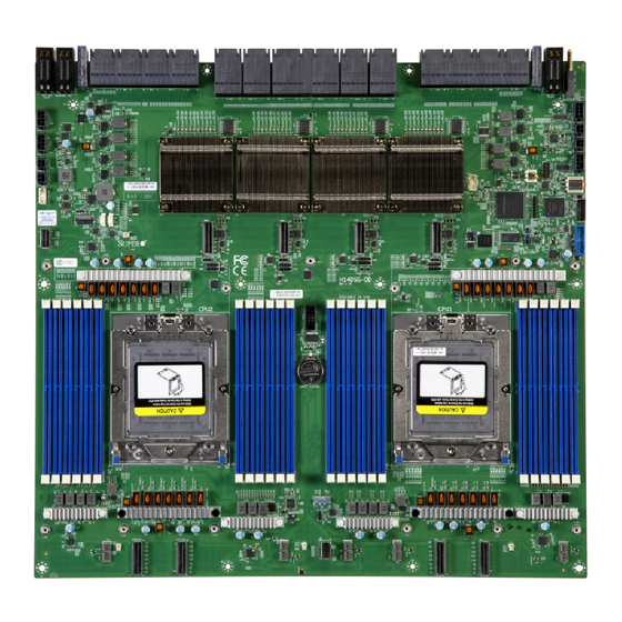
- Page 11 H14DSG-OD: Introduction Figure 1-1. Motherboard Image...
- Page 12 H14DSG-OD: Introduction 1.1 Quick Reference For details on the H14DSG- OD motherboard layout, features, and other quick reference information, refer to the content below. Motherboard Layout Figure 1-2. Motherboard Layout...
- Page 13 H14DSG-OD: Introduction Notes: "Component Installation" on page 22 for detailed information on jumpers, connectors, and LED indicators. "■" indicates the location of pin 1. Components not documented are for internal testing-purposes only. Use only the correct type of onboard CMOS battery as specified by the manufacturer.
- Page 14 H14DSG-OD: Introduction Quick Reference Table Jumper Description Default Setting JBT1 CMOS Clear Open (Normal) JPFR1 PFR Function Open (Normal) JPFR2 PFR Function Open (Normal) JPFR3 PFR Function Open (Normal) JPG1 VGA Enable/Disable Pins 1-2 (Enable) JUID1 Switch Function UID/Reset Pins 1-2 (UID)
- Page 15 H14DSG-OD: Introduction Connector Description Front Fan Board I2C JPWR3, JPWR12 12 V Power to BF3 Card 12 V Power to Backplane JPWR4 (BPN-NVME5-HS119N-S8L or BPN-NVME5-LB16A-S10) JPWR6 54 V Power to Front Fan Board (AOM-528G-FAN-CAS2) JPWR11 12 V Power to E1.S (BPN-E1S5-GP101M) JPWR13 12 V Power to M.2 Module (AOC-SMG4-2M2 or AOM-S3808NI-4NM)
- Page 16 H14DSG-OD: Introduction System Block Diagram Figure 1-3. System Block Diagram...
- Page 17 H14DSG-OD: Introduction 1.2 Motherboard Features Motherboard Features Dual AMD EPYC™ 9005/9004 Series Processors in Socket SP5 Memory Up to 6 TB registered ECC DDR5 4800 MT/s speed in 24 DIMM slots with AMD EPYC 9004 Series processors installed Up to 9 TB registered ECC DDR5 6000 MT/s speed in 24 DIMM slots with AMD EPYC...
- Page 18 H14DSG-OD: Introduction Motherboard Features Power Management ACPI power management (S5) Power button override mechanism Wake-On-LAN Power-on mode for AC power recovery System Health Monitoring Onboard voltage monitoring for +3.3 V, +12 V, +3.3 VStb, +5 VStb, Vcore, Vmem Onboard temperature monitoring for CPU, System, Memory, and Peripheral...
- Page 19 H14DSG-OD: Introduction 1.3 Platform Overview Built upon the functionality and capability of AMD EPYC™ in Socket SP5, the H14DSG-OD motherboard offers maximum I/O expandability, energy efficiency, and data reliability in a 3-nm (Zen 5c) and 4- nm (Zen 5) process architecture, and is optimized for embedded storage solutions, networking applications, or cloud-computing platforms.
- Page 20 H14DSG-OD: Introduction 1.4 System Health Monitoring Onboard Voltage Monitors An onboard voltage monitor will continuously scan the voltages of the onboard chipset, memory, processor, and battery. Once a voltage becomes unstable, a warning is given or an error message is sent to the screen. You can adjust the voltage thresholds to define the sensitivity of the voltage monitor.
- Page 21 H14DSG-OD: Introduction 1.5 ACPI Features ACPI stands for Advanced Configuration and Power Interface. The ACPI specification defines a flexible and abstract hardware interface that provides a standard way to integrate power management features throughout a computer system, including its hardware, operating system and application software.
- Page 22 Component Installation This chapter provides instructions on installing and replacing main system components for the H14DSG-OD motherboard. To prevent compatibility issues, only use components that match the specifications and/or part numbers given. Installation or replacement of most components require that power first be removed from the system.
- Page 23 H14DSG-OD: Component Installation Headers and Connections Front/Rear I/O Module Connectors I/O Module Connectors Jumper Settings LED Indicators...
- Page 24 H14DSG-OD: Component Installation 2.1 Static-Sensitive Devices Electrostatic Discharge (ESD) can damage electronic components. To avoid damaging your motherboard, it is important to handle it very carefully. The following measures are generally sufficient to protect your equipment from ESD. Precautions Use a grounded wrist strap designed to prevent static discharge.
- Page 25 H14DSG-OD: Component Installation 2.2 Motherboard Installation All motherboards have standard mounting holes to fit different types of chassis. Make sure that the locations of all the mounting holes for both the motherboard and the chassis match. Although a chassis may have both plastic and metal mounting fasteners, metal ones are highly recommended because they ground the motherboard to the chassis.
- Page 26 H14DSG-OD: Component Installation Figure 2-2. Motherboard Mounting Holes...
- Page 27 H14DSG-OD: Component Installation Installing the Motherboard 1. Install the I/O shield into the back of the chassis, if applicable. Figure 2-3. Install the I/O Shield Note: Images displayed are for illustration purposes only. The components installed in your system may or may not look exactly the same as the graphics shown in the manual.
- Page 28 H14DSG-OD: Component Installation Figure 2-5. Align the Mounting Holes 4. Install standoffs in the chassis as needed. 5. Install the motherboard into the chassis carefully to avoid damaging other motherboard components. 6. Insert pan head #6 screws into the mounting holes on the motherboard and the matching mounting holes on the chassis.
- Page 29 Install the processor in the socket and the motherboard into the chassis before installing the heatsink. When buying a processor separately, use only a Supermicro certified heatsink. Refer to the Supermicro website for the most recent processor support. When installing the heatsink, ensure a torque driver set to the correct force is used for each screw.
- Page 30 H14DSG-OD: Component Installation Figure 2-6. Removing Screw from the Force Frame 2. Lift the rail frame up by gripping the lift tabs near the front end of the rail frame. While keeping a secure grip of the rail frame, lift it to a position so you can do the next step of removing the external cap.
- Page 31 H14DSG-OD: Component Installation Figure 2-8. Remove the Cap Installing the Processor into the Frame 1. The processor package is shipped from the factory with the carrier frame pre- assembled. Grip the handle of the carrier frame/processor assembly from its shipping tray, and while gripping the handle, align the flanges of the carrier frame onto the rails of the rail frame so its pins will be at the bottom when the rail frame is lowered later.
- Page 32 H14DSG-OD: Component Installation 3. Lift up the rail frame until it securely rests in upright position. Then remove the PnP cover cap from the socket below. Grip the two lift tabs marked "Remove" at the middle of the cap and pull vertically upwards to remove the PnP cover cap.
- Page 33 H14DSG-OD: Component Installation 5. Use a T20 bit torque driver, set at 12.5–15.0 kgf-cm (10.8–13.0 in-lbf) to prevent damage to the processor. Replace and tighten the screws in the same order they were removed. When finished, the force frame will be secure over both the rail frame and processor package.
- Page 34 H14DSG-OD: Component Installation Figure 2-9. Heatsink Placement 2. Using a T20 torque driver, tighten the screws using the diagonal tightening pattern and torque specifications printed on the heatsink. Tighten the two center screws completely before tightening the four corner screws.
- Page 35 H14DSG-OD: Component Installation 7. Gripping the rail frame, rotate it downwards till it rests above and locks over the socket housing in its horizontal position. 8. Push and rotate down the force frame till it is over the external cap and rail frame into a horizontal position.
- Page 36 Note: Check the Supermicro website for recommended memory modules. Memory Support The H14DSG-OD supports up to 9 TB of ECC DDR5 memory in 24 DIMM slots. Refer to the tables below for additional information. Populating RDIMM/RDIMM 3DS DDR5 Memory Modules with...
- Page 37 H14DSG-OD: Component Installation The motherboard will support an odd number amount of memory modules. However, to achieve the best memory performance, a balanced memory population is recommended. DIMM Population This table shows the recommended slots to populate. DIMM Population Guide...
- Page 38 H14DSG-OD: Component Installation Figure 2-10. DIMM Labels DIMM Installation Important: Do not use excessive force when pressing the release tabs on the ends of the DIMM socket to avoid causing any damage to the memory module or the DIMM socket.
- Page 39 H14DSG-OD: Component Installation Figure 2-11. Unlock the DIMM Slot 3. Align the key of the DIMM with the receptive point on the memory slot. Figure 2-12. Align the DIMM Slot with the Receptive Point 4. Align the notches on both ends of the module against the receptive points on the ends of...
- Page 40 H14DSG-OD: Component Installation Figure 2-13. Align the Notches 5. Press both ends of the module straight down into the slot until the module snaps into place. 6. Press the release tabs to the lock positions to secure the DIMM into the slot.
- Page 41 H14DSG-OD: Component Installation DIMM Removal Important: Do not use excessive force when pressing the release tabs on the ends of the DIMM socket to avoid causing any damage to the memory module or the DIMM socket. Handle memory modules with care. Carefully follow all the instructions given in "Static-...
- Page 42 H14DSG-OD: Component Installation 2.5 Battery Removal and Installation Battery Removal To remove the onboard battery, follow the steps below: 1. Power off your system and unplug your power cable. 2. Locate the onboard battery as shown below. 3. Using a tool such as a pen or a small screwdriver, push the battery lock outwards to unlock it.
- Page 43 Refer to the following sections for information about connections, jumpers, and LEDs for the H14DSG-OD motherboard. Power Supply Connections For information about the power connections of the H14DSG-OD motherboard, refer to the following content. Power Supply As with all computer products, a stable power source is necessary for proper and reliable operation.
- Page 44 H14DSG-OD: Component Installation 8-Pin Power Pin Definitions Pin# Definition Pin# Definition Ground +12 V Ground +12 V Ground +12 V Ground +12 V E1.S Backplane, M.2 Module, BlueField-3 Risers, and BlueField-3 Bridge Boards 12 V 4-pin Power Connectors JPWR11, JPWR13, JPWR14, and JPWR15 are 4-pin 12 VDC power inputs. JPWR11 provides power to the system's E1.S backplane.
- Page 45 Ground TPM/Port 80 Header The JTPM1 header on the H14DSG-OD motherboard is used to connect a Trusted Platform Module (TPM)/Port 80, which is available from Supermicro (optional). A TPM/Port 80 connector is a security device that supports encryption and authentication in hard drives. It allows the motherboard to deny access if the TPM associated with the hard drive is not installed in the system.
- Page 46 The NVMe / SATA SMBus (I2C) header (JRSI2C1) provides hot-plug support via a dedicated SMBus interface. This feature is only available for a Supermicro complete system with an Supermicro-proprietary NVMe / SATA add-on card and a proper cable installed. See the table below for pin definitions.
- Page 47 In addition, there are six PCIe 5.0 ExaMax connectors (JNIC1 to 6) to connect to the NIC card carrier board, which supports eight PCIe 5.0 x16 connections. SATA Port The H14DSG-OD motherboard has one SATA 3.0 port (JS1) that is supported by ASMEDIA ASM1061. Front/Rear I/O Module Connectors I/O Module Connectors Two connectors on the motherboard provide I/O module connections.
- Page 48 H14DSG-OD: Component Installation Jumper Settings To modify the operation of the motherboard, jumpers can be used to choose between optional settings. Jumpers create shorts between two pins to change the function of the connector. Pin 1 is identified with a square solder pad on the printed circuit board. See the diagram below for an example of jumping pins 1 and 2.
- Page 49 Onboard Power LED (LED1) The Onboard Power LED is located at LED1 on the H14DSG-OD motherboard. When this LED is on, the system is on. Be sure to turn off the system and unplug the power cord before removing or installing components.
- Page 50 BMC Reset or Cold Boot BMC Heartbeat LED (LED3) A BMC Heartbeat LED is located at LED3 on the H14DSG-OD motherboard. When this LED is blinking, the BMC is functioning normally. For a detailed diagram of the H14DSG- OD motherboard, see the layout under "Quick...
- Page 51 H14DSG-OD: Troubleshooting Chapter 3: Troubleshooting The following content contains information on common issues and how to resolve them. 3.1 Troubleshooting Procedures Before Power On No Power No Video System Boot Failure Memory Errors Losing the System's Setup Configuration If the System Becomes Unstable 3.2 Technical Support Procedures...
- Page 52 H14DSG-OD: Troubleshooting 3.1 Troubleshooting Procedures Use the following procedures to troubleshoot your system. If you have followed all of the procedures below and still need assistance, refer to the "Technical Support Procedures" on page 55 "Returning Merchandise for Service" on page 58 section(s) in this chapter.
- Page 53 H14DSG-OD: Troubleshooting 1. Check the screen for an error message. 2. Clear the CMOS settings by unplugging the power cord and contacting both pads on the CMOS clear jumper. Restart the system. Refer to "CMOS Clear" on page 3. Remove all components from the motherboard and turn on the system with only one DIMM installed.
- Page 54 H14DSG-OD: Troubleshooting 2. Memory support: Make sure that the memory modules are supported. Refer to the product page on our website at https://www.supermicro.com. Test the modules using memtest86 or a similar utility. Note: Click on the "Tested Memory List" link on the motherboard's product page to see a list of supported memory.
- Page 55 Before contacting Technical Support, take the following steps. Also, note that as a motherboard manufacturer, Supermicro also sells motherboards through its channels, so it is best to first check with your distributor or reseller for troubleshooting services. They should know of any possible problems with the specific system configuration that was sold to you.
- Page 56 H14DSG-OD: Troubleshooting 3.3 Motherboard Battery For information on removing, disposing of, and replacing the motherboard battery of your system, refer to "Battery Removal and Installation" on page...
- Page 57 H14DSG-OD: Troubleshooting 3.4 Where to Get Replacement Components If you need replacement parts for your H14DSG-OD motherboard, to ensure the highest level of professional service and technical support, purchase exclusively from our Supermicro Authorized Distributors/System Integrators/Resellers. A list can be found on the Supermicro website: https://www.supermicro.com...
- Page 58 For faster service, RMA authorizations can be requested online at the following page: https://www.supermicro.com/RmaForm Whenever possible, repack the motherboard in the original Supermicro carton, using the original packaging material. If these are no longer available, be sure to pack the motherboard securely, using packaging material to surround the motherboard so that it does not shift within the carton and become damaged during shipping.
- Page 59 H14DSG-OD: Troubleshooting 3.6 Feedback Supermicro values your feedback as we strive to improve our customer experience in all facets of our business. Email us at Techwriterteam@supermicro.com to provide feedback on our manuals.
- Page 60 H14DSG-OD: UEFI BIOS Chapter 4: UEFI BIOS The following content contains information on BIOS configuration with the H14DSG- OD motherboard. 4.1 Introduction 4.2 Main Setup 4.3 Advanced Setup Configuration 4.4 BMC 4.5 Event Logs 4.6 Security 4.7 Boot 4.8 Save & Exit...
- Page 61 H14DSG-OD: UEFI BIOS 4.1 Introduction This chapter describes the AMIBIOS™ Setup utility for the motherboard. The BIOS is stored on a chip and can be easily upgraded using the UEFI script (flash.nsh), the BMC WebUI, or the SuperServer Automation Assistant (SAA) utility.
- Page 62 H14DSG-OD: UEFI BIOS The Main BIOS screen has two main frames. The left frame displays all the options that can be configured. “Grayed- out” options cannot be configured. The right frame displays the key legend. Above the key legend is an area reserved for a text message. When an option is selected in the left frame, it is highlighted in white.
- Page 63 H14DSG-OD: UEFI BIOS 4.2 Main Setup The Main setup screen appears when the AMI BIOS Setup utility is first entered. To return to the Main setup screen, select the Main tab at the top of the screen. The Main BIOS setup screen is shown below.
- Page 64 H14DSG-OD: UEFI BIOS Build Date This feature displays the date when the version of the BIOS ROM used in the system was built. CPLD Version This feature displays the version of the Complex-Programmable Logical Device (CPLD) used in the system.
- Page 65 H14DSG-OD: UEFI BIOS 4.3 Advanced Setup Configuration Use the arrow keys to select the Advanced submenu and press <Enter> to access the submenu items. Figure 4-2. Advanced Setup Configuration Screen Tab Important: Use caution when changing the Advanced settings. An incorrect value, an improper DRAM frequency, or a wrong BIOS timing setting may cause the system to malfunction.
- Page 66 H14DSG-OD: UEFI BIOS are Disabled and Enabled. Note: BIOS POST messages are always displayed regardless of the setting of this feature. Option ROM Messages Use this feature to set the display mode for the Option ROM. Select Keep Current to display the current AddOn ROM display settings.
- Page 67 H14DSG-OD: UEFI BIOS Power Button Function This feature controls how the system shuts down when the power button is pressed. Select 4 Seconds Override to power off the system after pressing and holding the power button for four seconds or longer. Select Instant Off to instantly power off the system as soon as you press the power button.
- Page 68 H14DSG-OD: UEFI BIOS Fast Short REP MOVSB (FSRM) This setting controls whether a specific memory copy instruction (REP MOVSB) is optimized for speed. The options are Auto, Enabled, and Disabled. Enhanced REP MOVSB/STOSB (ERSM) This setting optimizes CPU string operations. Disabling ERSM (setting it to 0) can be useful for performance analysis if supported by the operating system.
- Page 69 H14DSG-OD: UEFI BIOS ►CPU1 Information CPU Configuration These sections are for informational purposes. They will display some details about the detected CPUs on the motherboard, such as: CPU Version Number of Cores Running Processor Family Processor Model Microcode Patch Level...
- Page 70 H14DSG-OD: UEFI BIOS CPU1 PCIe Package Group P0 This setting selects the PCIe port bifurcation configuration for the selected slot. The options are Auto, x4x4x4x4, x4x4x8, x8x4x4, x8x8, x16, and SATA. CPU1 PCIe Package Group 01 This setting selects the PCIe port bifurcation configuration for the selected slot. The options are Auto, x4x4x4x4, x4x4x8, x8x4x4, x8x8, and x16.
- Page 71 H14DSG-OD: UEFI BIOS CPU2 PCIe Package Group P1 This setting selects the PCIe port bifurcation configuration for the selected slot. The options are Auto, x4x4x4x4, x4x4x8, x8x4x4, x8x8, and x16. CPU2 PCIe Package Group G1 This setting selects the PCIe port bifurcation configuration for the selected slot. The options are Auto, x4x4x4x4, x4x4x8, x8x4x4, x8x8, and x16.
- Page 72 H14DSG-OD: UEFI BIOS Package Power Limit Control Use Auto to apply the default power limit (PPT) or Manual to set a custom PPT. The options are Manual and Auto. Determinism Control Use this setting to configure the level of performance determinism. The options are Manual and Auto.
- Page 73 H14DSG-OD: UEFI BIOS Sync Header Bypass This setting controls the inclusion of synchronization headers in data transmissions. The options are Enabled, Disabled, and Auto. ►xGMI Configuration xGMI Link Width Control This setting controls the number of lanes used for the xGMI interface. When the setting is set to Manual, the "xGMI Force Link Width Control"...
- Page 74 H14DSG-OD: UEFI BIOS DRAM Scrub Time This setting specifies the frequency of memory scrubbing, which helps maintain data integrity by refreshing memory contents. The options are Disabled, 1 hour, 4 hours, 6 hours, 8 hours, 12 hours, 16 hours, 24 hours, and 48 hours.
- Page 75 H14DSG-OD: UEFI BIOS PCI AER Support This setting controls the Advanced Error Reporting (AER) capability for PCIe devices in the system. The options are Enabled and Disabled. NUMA Nodes Per Socket Use this setting to specify the number of desired NUMA (Non-Uniform Memory Access) nodes per socket.
- Page 76 H14DSG-OD: UEFI BIOS Serial Port 2 Configuration Menu ►Serial Port 2 Configuration Note: It can be "Serial Port 2 Configuration" or "SOL Configuration" based on your system support. Serial Port 2/SOL ("Serial Port 2" or "SOL" based on your system support) Select Enabled to enable serial port 2 (or SOL).
- Page 77 H14DSG-OD: UEFI BIOS Terminal Type Use this feature to select the target terminal emulation type for Console Redirection. Select VT100 to use the ASCII character set. Select VT100+ to add color and function key support. Select ANSI to use the extended ASCII character set. Select VT-UTF8 to use UTF8 encoding to map Unicode characters into one or more bytes.
- Page 78 H14DSG-OD: UEFI BIOS Resolution 100x31 Select Enabled for extended- terminal resolution support. The options are Disabled and Enabled. Putty KeyPad This feature selects Function Keys and KeyPad settings for Putty, which is a terminal emulator designed for the Windows OS. The options are VT100, LINUX, XTERMR6, SCO, ESCN, and VT400.
- Page 79 H14DSG-OD: UEFI BIOS BME DMA Mitigation This setting enables or disables Bus Mastering Error (BME) Direct Memory Access (DMA) mitigation for protection during the pre-boot process. The options are Disabled and Enabled. PCIe ARI Support This setting enables alternative routing- ID interpretation. The options are Disabled, Enabled, and Auto.
- Page 80 H14DSG-OD: UEFI BIOS CPU SLOT3-10 PCIe 5.0 x16 OPROM This setting enables or disables the Option ROM for the SLOT3 PCIe 5.0 x16 interface. The options are Disabled and EFI. M.2-C1 OPROM This setting enables or disables the Option ROM for the M.2-C1 slot. The options are Disabled and EFI.
- Page 81 H14DSG-OD: UEFI BIOS Network Configuration Menu Network Stack Select Enabled to enable Preboot Execution Environment (PXE) or Unified Extensible Firmware Interface (UEFI) for network stack support. The options are Disabled and Enabled. IPv4 PXE Support (Available when "Network Stack" is set to Enabled) Select Enabled to enable IPv4 PXE boot support.
- Page 82 H14DSG-OD: UEFI BIOS Route Table Gateway addresses DNS addresses Interface ID DAD Transmit Count The number of consecutive Neighbor Solicitation messages sent while performing Duplicate Address Detection on a tentative address. A value of zero indicates that Duplicate Address Detection is not performed. The default value is 1.
- Page 83 (WARNING: Security Risk!). Important: Disabling "HTTPS Boot Checks Hostname" is a violation of RFC 6125 and may expose you to Man-in-the-Middle Attacks. Supermicro is not responsible for any and all security risks incurred by you disabling this feature. Priority of HTTP Boot Instance of Priority 1: (Available when your motherboard supports this feature) This feature sets the rank target port.
- Page 84 Supermicro KMS TCP Port number Use this feature to set the TCP port number used in Supermicro KMS Server. The valid range is 100–9999. The default setting is 5696. Do not change the default setting unless a different TCP port number has been specified and used in the Supermicro KMS Server.
- Page 85 H14DSG-OD: UEFI BIOS ►CA Certificate This setting provides options for managing the Certificate Authority (CA) certificate.The options are Update, Delete, and Export. ►Client Certificate This setting provides options for managing the client certificate.The options are Update, Delete, and Export. ►Client Private Key...
- Page 86 Notes: Be sure that the KMS server is ready before configuring this feature. Use the professional KMS server solutions (e.g., Thales Server) or the Supermicro PyKMIP Software Package to establish the KMS server. KMS Server Retry Count (Available when "TPM Security Policy" and "USB Security Policy"...
- Page 87 H14DSG-OD: UEFI BIOS When this feature has previously been set to Enabled, the options are Enabled and Reset. To disable the TPM Security Policy, set this feature to Reset. When this feature is set to reset, the system and TCG NVMe devices chosen in "Super-Guardians Protection Policy" will be in the unprotected mode.
- Page 88 H14DSG-OD: UEFI BIOS When this feature has been previously set to Enabled, the options are Enabled and Reset. To disable the USB Security Policy, set this feature to Reset. When this feature is set to Reset, the system and TCG NVMe devices chosen in "Super-Guardians Protection Policy" will be in the unprotected mode.
- Page 89 H14DSG-OD: UEFI BIOS This setting specifies the type of memory to use from the available memory pool in the system to create a disk. the options are Boot Service Data and Reserved. Create raw Size (Hex): Set the size of the RAM disk. The valid size should be multiples of the RAM disk block size.
- Page 90 H14DSG-OD: UEFI BIOS Properties: Status / Backplane / CacheVault / Enclosure / JBODs / Drive Groups / Virtual Drives ►View Server Profile The setting shows the UEFI spec version that this system supports and menu options as below: Server: UEFI Spec Version ►Controller Management...
- Page 91 H14DSG-OD: UEFI BIOS Note: This section is provided for reference only, for the driver health status will differ depending on the drivers installed in your system. It's also based on your system configuration and the environment that your system is operating in.
- Page 92 H14DSG-OD: UEFI BIOS 4.4 BMC Use this menu to configure Baseboard Management Console (BMC) settings. Figure 4-4. BMC Screen Tab BMC Firmware Revision This feature indicates the BMC firmware revision used in your system. BMC STATUS This feature indicates the status of the BMC firmware installed in your system.
- Page 93 H14DSG-OD: UEFI BIOS SEL Components Select Enabled to enable all system event logging upon system boot. The options are Disabled and Enabled. Erasing Settings Erase SEL (Available when "SEL Components" is set to Enabled) Select (Yes, On next reset) to erase all system event logs upon next system boot. Select (Yes, On every reset) to erase all system event logs upon each system reboot.
- Page 94 H14DSG-OD: UEFI BIOS Station IP Address This feature displays the Station IP address in decimal and in dotted quad form (i.e., 172.29.176.131). It is available for configuration when "Configuration Address Source" above is set to Static. Subnet Mask This feature displays the sub- network that this computer belongs to. It is available for configuration when "Configuration Address Source"...
- Page 95 H14DSG-OD: UEFI BIOS Prefix Length This feature displays the prefix length. It is available for configuration when "Configuration Address Source" above is set to Static Configuration. Gateway IP This feature displays the IPv6 gateway IP address. It is available for configuration when "Configuration Address Source"...
- Page 96 H14DSG-OD: UEFI BIOS 4.5 Event Logs Use this menu to configure Event Logs settings. Figure 4-5. Event Logs Screen Tab Note: After you've made any changes in this section, please be sure to reboot the system for the changes to take effect.
- Page 97 H14DSG-OD: UEFI BIOS Erasing Settings Erase Event Log (Available when "SMBIOS Event Log" is set to Enabled) Select No to keep the event log without erasing it upon next system bootup. Select (Yes, Next reset) to erase the event log upon next system reboot. The options are No, (Yes, Next reset), and (Yes, Every reset).
- Page 98 H14DSG-OD: UEFI BIOS 4.6 Security This menu allows you to configure the following security settings for the system. Figure 4-6. Security Screen Tab Disable Block Sid and Freeze Lock (Available when your storage devices support TCG) Select Enabled to allow SID authentication to be performed in TCG storage devices. The options are Disabled and Enabled.
- Page 99 The options are Disabled and Enabled. ►Supermicro Security Erase Configuration Use this submenu to configure the Supermicro-proprietary Security Erase settings. When this submenu is selected, the following information is displayed. Please note that the order of the following information may differ based on the storage devices being detected.
- Page 100 The options are Disabled and Enabled. HDD Security Configuration: ►Secure Boot The following information is displayed: System Mode Secure Boot Note: For detailed instructions on configuring Security Boot settings, refer to the Security Boot Configuration User's Guide at https://www.supermicro.com/support/manuals.
- Page 101 H14DSG-OD: UEFI BIOS 4.7 Boot Use this menu to configure Boot settings. Figure 4-7. Boot Screen Tab Boot Configuration Boot Mode Select Use this feature to select boot mode. The options are Legacy, UEFI, and Dual. Legacy to EFI Support Use this feature to enable system to boot to EFI OS after boot failed from legacy boot order.
- Page 102 H14DSG-OD: UEFI BIOS ►Add New Boot Option Use this feature to add a new boot option to the boot priority features for system boot. Note: This submenu is available when any storage device is detected by the BIOS. Add boot option Use this feature to specify the name for the new boot option.
- Page 103 H14DSG-OD: UEFI BIOS 4.8 Save & Exit Select Save & Exit from the BIOS Setup screen to configure the settings below. Figure 4-8. Save & Exit Screen Tab Save Options Discard Changes and Exit Use this feature to exit from the BIOS Setup utility without making any permanent changes to the system configuration and reboot the computer.
- Page 104 H14DSG-OD: UEFI BIOS Discard Changes Select this feature and press <Enter> to discard all changes made and return to the BIOS Setup utility. Default Options Restore Optimized Defaults Select this feature and press <Enter> to load manufacturer optimized default settings, which are intended for maximum system performance but not for maximum stability.
- Page 105 USB flash or media drive, or the BMC KVM console. 2. Retrieve the proper drivers. Go to the Supermicro web page for your motherboard and click on "Download the Latest Drivers and Utilities," select the proper driver, and copy it to a USB flash drive.
- Page 106 H14DSG-OD: Software Figure A-1. Select Boot Device 4. During Windows Setup, continue to the dialog box where you select the drives on which to install Windows. If the disk you want to use is not listed, click on the “Load driver” link...
- Page 107 6. After the Windows OS installation has completed, the system will automatically reboot multiple times for system updates. Driver Installation The Supermicro website contains drivers and utilities for your system at the following page: https://www.supermicro.com/wdl. Some of these drivers and utilities must be installed, such as the chipset driver. After accessing the website, go into the CDR_Images (in the parent directory of the above link) and locate the ISO file for your motherboard.
- Page 108 H14DSG-OD: Software Figure A-3. Driver Download Screenshot Note: Click the icons showing a hand writing on paper to view the readme files for each item. Click the computer icons to the right of these items to install each item (from top to bottom) one at a time.
- Page 109 For security, each system is assigned a unique default BMC password for the ADMIN user. The password can be found on a sticker on the motherboard and a sticker on the chassis, for Supermicro chassis. The sticker also displays the BMC MAC address. If necessary, the password can be reset using the Supermicro IPMICFG tool.
- Page 110 Should you have questions or experience difficulty, contact Supermicro's Technical Support department for assistance. Only certified technicians should attempt to install or configure components. Read this section in its entirety before installing or configuring components in the Supermicro H14DSG-OD motherboard. These...
- Page 111 H14DSG-OD: Standardized Warning Statements WARNUNG Es besteht Explosionsgefahr, wenn die Batterie durch einen falschen Typ ersetzt wird. Ersetzen Sie die Batterie nur durch den gleichen oder vom Hersteller empfohlenen Batterietyp. Entsorgen Sie die benutzten Batterien nach den Anweisungen des Herstellers.
- Page 112 H14DSG-OD: Standardized Warning Statements WAARSCHUWING Er bestaat explosiegevaar als de batterij wordt vervangen door een verkeerd type. Vervang de batterij slechts met hetzelfde of een equivalent type die door de fabrikant aanbevolen wordt. Gebruikte batterijen dienen overeenkomstig fabrieksvoorschriften afgevoerd te worden.
- Page 113 H14DSG-OD: Standardized Warning Statements המוצר סילוק !אזהרה המדינה וחוקי להנחיות בהתאם להיות חייב זה מוצר של סופי סילוק اﻟﯩﻄﻨﻴﺔ واﻟﻠﯩﺎﺋﺢ اﻟﻘﯩﺎﻧﻴﻦ ﻟﺠﻤﻴﻊ وﻓﻘﺎ ﻣﻌﻪ اﻟﺘﻌﺎﻣﻞ ﻳﻨﺒﻐﻲ اﻟﻤﻨﺘﺞ ﻫﺬا ﻣﻦ اﻟﻨﻬﺎﺋﻲ اﻟﺘﺨﻠﺺ ﻋﻨﺪ 경고! 이 제품은 해당 국가의 관련 법규 및 규정에 따라 폐기되어야 합니다.
Need help?
Do you have a question about the H14DSG-OD and is the answer not in the manual?
Questions and answers