Advertisement
Quick Links
Advertisement

Related Manuals for Supermicro H14SST-G


Summary of Contents for Supermicro H14SST-G
- Page 1 H14SST-G USER'S MANUAL Revision 1.0 (MNL-2756)
- Page 2 The products sold by Supermicro are not intended for and will not be used in life support systems, medical equipment, nuclear facilities or systems, aircraft, aircraft devices, aircraft/emergency communication devices or other critical systems whose failure to perform be reasonably expected to result in significant injury or loss of life or catastrophic property damage.
- Page 3 Technical Support email addresses can be found at: "Contacting Supermicro" on page 9 If you have any feedback on Supermicro product manuals, contact our writing team at: Techwriterteam@supermicro.com This manual may be periodically updated without notice. Check the Supermicro website for...
- Page 4 H14SST-G: Preface Conventions Used in the Manual Special attention should be given to the following symbols for proper installation and to prevent damage done to the components or injury to yourself. Warning! Indicates important information given to prevent equipment/property damage or personal injury.
- Page 5 H14SST-G: Contents Contents Contacting Supermicro Chapter 1: Introduction 1.1 Quick Reference Layout Quick Reference Table System Block Diagram 1.2 Motherboard Features 1.3 Platform Overview 1.4 System Health Monitoring Onboard Voltage Monitors Fan Status Monitor with Firmware Control Environmental Temperature Control 1.5 ACPI Features...
- Page 6 H14SST-G: Contents 2.6 Battery Removal and Installation Battery Removal Proper Battery Disposal Battery Installation 2.7 Connections, Jumpers, and LEDs Power Supply Power Connectors Headers and Connections Onboard Battery (BT1) M.2 Slots TPM/Port 80 Header Jumper Settings CMOS Clear JSATA1 LED Indicators...
- Page 7 Serial Port Console Redirection Menu PCIe/PCI/PnP Configuration Menu USB Configuration Network Configuration Menu SATA Configuration Menu HTTP Boot Configuration Menu Supermicro KMS Server Configuration Menu Super-Guardians Configuration Menu Supermicro Network Adapter Menu TLS Authenticate Configuration Menu Driver Health Menu 4.4 BMC...
- Page 8 H14SST-G: Contents Installing the OS Driver Installation BMC ADMIN User Password Appendix B: Standardized Warning Statements Battery Handling Product Disposal...
- Page 9 H14SST-G: Contacting Supermicro Contacting Supermicro Headquarters Address: Super Micro Computer, Inc. 980 Rock Ave. San Jose, CA 95131 U.S.A. Tel: +1 (408) 503-8000 Fax: +1 (408) 503-8008 Email: Marketing@supermicro.com (General Information) Sales-USA@supermicro.com (Sales Inquiries) Government_Sales-USA@supermicro.com (Gov. Sales Inquiries) Support@supermicro.com (Technical Support) RMA@Supermicro.com...
- Page 10 H14SST-G: Introduction Chapter 1: Introduction Congratulations on purchasing your computer motherboard from an industry leader. Supermicro motherboards are designed to provide you with the highest standards in quality and performance. 1.1 Quick Reference Layout Quick Reference Table System Block Diagram 1.2 Motherboard Features...
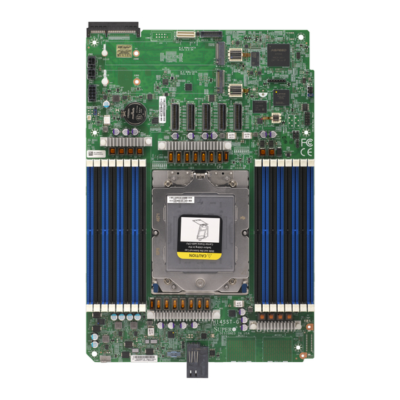
- Page 11 H14SST-G: Introduction 1.1 Quick Reference For details on the H14SST- G motherboard layout, features, and other quick reference information, refer to the content below. Layout Figure 1-1. H14SST-G Motherboard Image...
- Page 12 H14SST-G: Introduction Figure 1-2. H14SST-G Motherboard Layout...
- Page 13 H14SST-G: Introduction Notes: "Component Installation" on page 20 for detailed information on jumpers, connectors, and LED indicators. "■" indicates the location of pin 1. Components not documented are for internal testing only. Use only the correct type of onboard CMOS battery as specified by the manufacturer.
- Page 14 H14SST-G: Introduction Connector Description JTPM1 Trusted Platform Module/Port 80 Connector M.2-H1, M.2-H2 M.2 NVMe or SATA SSDs System Block Diagram Figure 1-3. System Block Diagram...
- Page 15 H14SST-G: Introduction 1.2 Motherboard Features Motherboard Features Single AMD EPYC™ 9005 Series processors in Socket SP5 Memory Up to 6 TB of registered ECC DDR5 memory across 16 DIMM slots, with speeds up to 4400 MT/s for 2DPC and up to 5200 MT/s for 1DPC.
- Page 16 H14SST-G: Introduction Motherboard Features Power Management ACPI power management (S5) Wake-on-LAN Power-on mode for AC power recovery System Health Monitoring Onboard voltage monitoring for 3.3 V, +5 V, +12 V, +3.3 VStby, +5 VStby, Vcore, CPU temperature, system temperature, peripheral temperature, memory temperature, and NVMe...
- Page 17 H14SST-G: Introduction 1.3 Platform Overview Built upon the functionality and capability of the AMD EPYC™ 9005 Series in Socket SP5, the H14SST- G motherboard offers maximum I/O expandability, energy efficiency, and data reliability in a 3-nm process architecture, and is optimized for embedded storage solutions, networking applications, or cloud-computing platforms.
- Page 18 H14SST-G: Introduction 1.4 System Health Monitoring Onboard Voltage Monitors An onboard voltage monitor will continuously scan the voltages of the onboard chipset, memory, processor, and battery. Once a voltage becomes unstable, a warning is given or an error message is sent to the screen. You can adjust the voltage thresholds to define the sensitivity of the voltage monitor.
- Page 19 H14SST-G: Introduction 1.5 ACPI Features ACPI stands for Advanced Configuration and Power Interface. The ACPI specification defines a flexible and abstract hardware interface that provides a standard way to integrate power management features throughout a computer system, including its hardware, operating system and application software.
- Page 20 Component Installation This chapter provides instructions on installing and replacing main system components for the H14SST-G motherboard. To prevent compatibility issues, only use components that match the specifications and/or part numbers given. Installation or replacement of most components require that power first be removed from the system.
- Page 21 H14SST-G: Component Installation Headers and Connections Jumper Settings LED Indicators...
- Page 22 H14SST-G: Component Installation 2.1 Static-Sensitive Devices Electrostatic Discharge (ESD) can damage electronic components. To avoid damaging your motherboard, it is important to handle it very carefully. The following measures are generally sufficient to protect your equipment from ESD. Precautions Use a grounded wrist strap designed to prevent static discharge.
- Page 23 H14SST-G: Component Installation 2.2 Motherboard Installation All motherboards have standard mounting holes to fit different types of chassis. Make sure that the locations of all the mounting holes for both the motherboard and the chassis match. Although a chassis may have both plastic and metal mounting fasteners, metal ones are highly recommended because they ground the motherboard to the chassis.
- Page 24 H14SST-G: Component Installation 2.3 Location of Mounting Holes Note: To avoid damaging the motherboard and its components, do not use a force greater than 8 lbf-in on each mounting screw during motherboard installation.Some components are very close to the mounting holes. Take precautionary measures to avoid damaging these components when installing the motherboard to the chassis..
- Page 25 H14SST-G: Component Installation Installing the Motherboard 1. Install the I/O shield into the back of the chassis, if applicable. Note: Images displayed are for illustration only. The components installed in your system may or may not look exactly the same as the graphics shown in the manual.
- Page 26 H14SST-G: Component Installation Figure 2-5. Align the Mounting Holes 4. Install standoffs in the chassis as needed. 5. Install the motherboard into the chassis carefully to avoid damaging other motherboard components. 6. Insert pan head #6 screws into the mounting holes on the motherboard and the matching mounting holes on the chassis.
- Page 27 Install the processor in the socket and the motherboard into the chassis before installing the heatsink. When buying a processor separately, use only a Supermicro certified heatsink. Refer to the Supermicro website for the most recent processor support. When installing the heatsink, ensure a torque driver set to the correct force is used for each screw.
- Page 28 H14SST-G: Component Installation Figure 2-6. Removing Screw from the Force Frame 2. Lift the rail frame up by gripping the lift tabs near the front end of the rail frame. While keeping a secure grip of the rail frame, lift it to a position so you can do the next step of removing the external cap.
- Page 29 H14SST-G: Component Installation Figure 2-8. Remove the Cap Installing the Processor into the Frame 1. The processor package is shipped from the factory with the carrier frame pre- assembled. Grip the handle of the carrier frame/processor assembly from its shipping tray, and while gripping the handle, align the flanges of the carrier frame onto the rails of the rail frame so its pins will be at the bottom when the rail frame is lowered later.
- Page 30 H14SST-G: Component Installation 3. Lift up the rail frame until it securely rests in upright position. Then remove the PnP cover cap from the socket below. Grip the two lift tabs marked "Remove" at the middle of the cap and pull vertically upwards to remove the PnP cover cap.
- Page 31 H14SST-G: Component Installation 5. Use a T20 bit torque driver, set at 12.5–15.0 kgf-cm (10.8–13.0 in-lbf) to prevent damage to the processor. Replace and tighten the screws in the same order they were removed. When finished, the force frame will be secure over both the rail frame and processor package.
- Page 32 H14SST-G: Component Installation 1. Place the heatsink so that it rests on the processor aligning the six screws on the socket frame. Figure 2-9. Heatsink Placement 2. Using T20 torque driver, tighten the screws using the diagonal tightening pattern and torque specifications printed on the heatsink.
- Page 33 H14SST-G: Component Installation 6. Grip the handle on the external cap and return it to the rail frame sliding it downwards till it rests in the frame. 7. Gripping the rail frame, rotate it downwards till it rests above and locks over the socket housing in its horizontal position.
- Page 34 éviter tout dommage. Note: Check the Supermicro website for recommended memory modules. Memory Support The H14SST-G supports up to 6 TB of ECC DDR5 RDIMM/3DSRDIMM memory in 16 DIMM slots. Populating RDIMM/RDIMM 3DS DDR5 Memory Modules with ™...
- Page 35 H14SST-G: Component Installation General Guidelines for Optimizing Memory Performance It is recommended to use DDR5 memory of the same type, size, and speed. Mixed DIMM speeds can be installed. However, all DIMMs will run at the speed of the slowest DIMM.
- Page 36 H14SST-G: Component Installation Figure 2-10. DIMM Numbering DIMM Installation Warning! Do not use excessive force when pressing the release tabs on the ends of the DIMM socket to avoid causing any damage to the memory module or the DIMM socket. Handle memory modules with care. Carefully follow all the instructions given in "Static-Sensitive Devices"...
- Page 37 H14SST-G: Component Installation Avertissement! N'exercez pas de force excessive lorsque vous appuyez sur les languettes de dégagement situées aux extrémités du support DIMM afin d'éviter d'endommager le module de mémoire ou le support DIMM. Manipulez les modules de mémoire avec précaution. Suivez attentivement toutes les instructions fournies dans «...
- Page 38 5. Press both ends of the module straight down into the slot until the module snaps into place. 6. Press the release tabs to the lock positions to secure the DIMM into the slot. Figure 2-14. Press Both Ends For a detailed diagram of the H14SST-G motherboard, see the layout under "Quick Reference" on page...
- Page 39 Press both release tabs on the ends of the DIMM socket to unlock it. Once the DIMM is loosened, remove it from the memory slot. For a detailed diagram of the H14SST-G motherboard, see the layout under "Quick Reference" on page...
- Page 40 H14SST-G: Component Installation 2.6 Battery Removal and Installation Battery Removal To remove the onboard battery, follow the steps below: 1. Power off your system and unplug your power cable. 2. Locate the onboard battery as shown below. 3. Using a tool such as a pen or a small screwdriver, push the battery lock outwards to unlock it.
- Page 41 H14SST-G: Component Installation 1. Identify the battery's polarity. The positive (+) side should be facing up. 2. Insert the battery into the battery holder and push it down until you hear a click to ensure that the battery is securely locked.
- Page 42 Two M.2 slots are located at M.2-H1 and M.2-H2 on the motherboard. They support PCIe 5.0 x4 M.2 NVMe SSDs in the 2280 and 22110 form factors. For a detailed diagram of the H14SST-G motherboard, see the layout under "Quick Reference"...
- Page 43 H14SST-G: Component Installation TPM/Port 80 Header The JTPM1 header on the H14SST-G motherboard is used to connect a Trusted Platform Module (TPM)/Port 80, which is available from Supermicro (optional). A TPM/Port 80 connector is a security device that supports encryption and authentication in hard drives. It allows the motherboard to deny access if the TPM associated with the hard drive is not installed in the system.
- Page 44 JBT1 on the H14SST- G motherboard is used to clear CMOS, which will also clear any passwords. Instead of pins, this jumper consists of contact pads to prevent accidentally clearing the contents of CMOS. For a detailed diagram of the H14SST-G motherboard, see the layout under "Quick Reference" on page Note: Clearing CMOS will also clear all passwords.
- Page 45 BMC Normal Onboard Power LED The Onboard Power LED is located on the H14SST-G motherboard. When this LED is on, the system is in a power-on state. Be sure to turn off the system and unplug the power cord before removing or installing components.
- Page 46 H14SST-G: Component Installation For a detailed diagram of the H14SST-G motherboard, see the layout under "Quick Reference" on page UID LED LED Indicator LED Color Definitions Blue: On System Identified...
- Page 47 H14SST-G: Troubleshooting Chapter 3: Troubleshooting The following content contains information on common issues and how to resolve them. 3.1 Troubleshooting Procedures Before Power On No Power No Video System Boot Failure Memory Errors Losing the System's Setup Configuration When the System Becomes Unstable 3.2 Technical Support Procedures...
- Page 48 H14SST-G: Troubleshooting 3.1 Troubleshooting Procedures Use the following procedures to troubleshoot your system. If you have followed all of the procedures below and still need assistance, refer to the "Technical Support Procedures" on page 52 "Returning Merchandise for Service" on page 55 section(s) in this chapter.
- Page 49 H14SST-G: Troubleshooting 1. Check the screen for an error message. 2. Clear the CMOS settings by unplugging the power cord and contacting both pads on the CMOS clear jumper. Restart the system. Refer to "CMOS Clear" on page 3. Remove all components from the motherboard and turn on the system with only one DIMM installed.
- Page 50 H14SST-G: Troubleshooting 2. Memory support: Make sure that the memory modules are supported. Refer to the product page on our website at https://www.supermicro.com. Test the modules using memtest86 or a similar utility. Note: Click on the "Tested Memory List" link on the motherboard's product page to see a list of supported memory.
- Page 51 H14SST-G: Troubleshooting the component in question in another system. If the new system works, the component is good and the old system has problems.
- Page 52 Before contacting Technical Support, take the following steps. Also, note that as a motherboard manufacturer, Supermicro also sells motherboards through its channels, so it is best to first check with your distributor or reseller for troubleshooting services. They should know of any possible problems with the specific system configuration that was sold to you.
- Page 53 H14SST-G: Troubleshooting 3.3 Motherboard Battery For information on removing, disposing of, and replacing the motherboard battery of your system, refer to "Battery Removal and Installation" on page...
- Page 54 H14SST-G: Troubleshooting 3.4 Where to Get Replacement Components If you need replacement parts for your H14SST-G motherboard, to ensure the highest level of professional service and technical support, purchase exclusively from our Supermicro Authorized Distributors/System Integrators/Resellers. A list can be found on the Supermicro website: https://www.supermicro.com...
- Page 55 For faster service, RMA authorizations can be requested online at the following page: https://www.supermicro.com/RmaForm Whenever possible, repack the motherboard in the original Supermicro carton, using the original packaging material. If these are no longer available, be sure to pack the motherboard securely, using packaging material to surround the motherboard so that it does not shift within the carton and become damaged during shipping.
- Page 56 H14SST-G: Troubleshooting 3.6 Feedback Supermicro values your feedback as we strive to improve our customer experience in all facets of our business. Email us at Techwriterteam@supermicro.com to provide feedback on our manuals.
- Page 57 H14SST-G: UEFI BIOS Chapter 4: UEFI BIOS The following content contains information on BIOS configuration with the H14SST- G motherboard. 4.1 Introduction 4.2 Main Setup 4.3 Advanced Setup Configurations 4.4 BMC 4.5 Event Logs 4.6 Security 4.7 Boot 4.8 Save & Exit...
- Page 58 H14SST-G: UEFI BIOS 4.1 Introduction This chapter describes the AMIBIOS™ Setup utility for the motherboard. The BIOS is stored on a chip and can be easily upgraded using a flash program. Note: Due to periodic changes to the BIOS, some settings may have been added or deleted and might not yet be recorded in this manual.
- Page 59 H14SST-G: UEFI BIOS Starting the Setup Utility To enter the BIOS Setup Utility, hit the Delete key while the system is booting-up. In most cases, the <Delete> key is used to invoke the BIOS setup screen. There are a few cases when other keys are used, such as <F1>, <F2>, etc.
- Page 60 H14SST-G: UEFI BIOS 4.2 Main Setup When you first enter the AMI BIOS Setup utility, you enter the Main setup screen. You can always return to the Main setup screen by selecting the Main tab on the top of the screen. The Main BIOS setup screen is shown below.
- Page 61 H14SST-G: UEFI BIOS Build Date This feature displays the date when the version of the BIOS ROM used in the system was built. CPLD Version This feature displays the version of the Complex-Programmable Logical Device (CPLD) used in the system.
- Page 62 H14SST-G: UEFI BIOS 4.3 Advanced Setup Configurations Use the arrow keys to select the Advanced submenu and press <Enter> to access the submenu items. Figure 4-2. Advanced BIOS Screen Warning! Take caution when changing the Advanced settings. An incorrect value, an improper DRAM frequency, or a wrong BIOS timing setting may cause the system to malfunction.
- Page 63 H14SST-G: UEFI BIOS Boot Feature Menu ►Boot Feature Quiet Boot Use this feature to select the screen between displaying the Power- on Self Test (POST) messages or the OEM logo upon bootup. Select Disabled to display the POST messages. Select Enabled to display the OEM logo instead of the normal POST messages. The options are Disabled and Enabled.
- Page 64 H14SST-G: UEFI BIOS power loss. The options are Stay Off, Power On, and Last State. Power Button Function This feature controls how the system shuts down when the power button is pressed. Select 4 Seconds Override to power off the system after pressing and holding the power button for four seconds or longer.
- Page 65 H14SST-G: UEFI BIOS Enhanced REP MOVSB/STOSB (ERSM) This setting optimizes CPU string operations. Disabling ERSM (setting to 0) can be used for analysis purposes if supported by the operating system. The options are Disabled, Enabled, and Auto. AVX512 Enable or disable AVX512. The options are Auto, Enabled, and Disabled.
- Page 66 H14SST-G: UEFI BIOS CPU1 PCIe Package Group P3 CPU1 PCIe Package Group G3 CPU1 PCIe Package Group P1 CPU1 PCIe Package Group G1 CPU1 PCIe Package Group P0 CPU1 PCIe Package Group G0 NB Configuration North Bridge Configuration IOMMU Use this setting to enable or disable IOMMU. The options are Disabled, Enabled, and Auto.
- Page 67 H14SST-G: UEFI BIOS Determinism Control Use this setting to configure the level of performance determinism. The options are Manual and Auto. APBDIS Use this setting to control the APBDIS feature. A value of 0 indicates "not APBDIS" (mission mode). The options are 0, 1, and Auto.
- Page 68 H14SST-G: UEFI BIOS ►Memory Configuration Memory Target Speed Use this setting to specify the memory target speed in MT/s. The options are Auto, DDR3600, DDR4000, DDR4400,.DDR4800, and DDR5200. Memory Interleaving This setting controls fabric level memory interleaving. Note that the channel, die and socket have requirements on memory populations and it will be ignored if the memory doesn't support the selected option.
- Page 69 H14SST-G: UEFI BIOS Trusted Computing Configuration Security Device Support If this feature and the TPM jumper on the motherboard are both set to Enabled, onboard security devices will be enabled for TPM (Trusted Platform Module) support to enhance data integrity and network security. Please reboot the system for a change on this setting to take effect.
- Page 70 H14SST-G: UEFI BIOS Super IO Configuration Menu ►Super IO Configuration Note: This submenu is available when your system supports this feature. The following information is displayed. Super IO Chip Select for Serial Port 1 or Serial Port 2. Serial Port 1 Configuration Menu...
- Page 71 H14SST-G: UEFI BIOS IRQ=3,4,5,6,7,9,10,11,12;), (IO=2F8h; IRQ=3,4,5,6,7,9,10,11,12;), (IO=3E8h; IRQ=3,4,5,6,7,9,10,11,12;), and (IO=2E8h; IRQ=3,4,5,6,7,9,10,11,12;). Serial Port 2 Attribute (Available for Serial Port 2 only) Select SOL to use serial port 2 as a Serial Over LAN (SOL) port for console redirection. The options are SOL and COM.
- Page 72 H14SST-G: UEFI BIOS Relaxed Ordering This setting determines whether PCI Express devices are permitted to bypass strict transaction ordering, which can lead to potential performance improvements. The options are Disabled and Enabled. Clock Spread Spectrum This setting allows the BIOS to monitor and reduce the level of Electromagnetic Interference (EMI) generated by system components.
- Page 73 H14SST-G: UEFI BIOS USB Configuration USB Configuration USB Module Version USB Controllers: 2 XHCIs USB Devices: 1 Keyboard, 1 Mouse, 3 Hubs XHCI Hand-off This setting provides a workaround for operating systems that do not support XHCI hand-off. The XHCI ownership change must be claimed by the XHCI driver.The options are Enabled and Disabled.
- Page 74 H14SST-G: UEFI BIOS This setting indicates whether the network address configured successfully. The options are Disabled and Enabled. Enable DHCP The options are Disabled and Enabled. Local IP Address Enter and IP address. Local NetMask Enter the Netmask address. Local Gateway Enter the Gateway IP address.
- Page 75 H14SST-G: UEFI BIOS Policy Use this feature to select how the policy is to be configured. The options are Automatic and Manual. ►Advanced Configuration Note: This submenu is available when "Policy" is set to Manual. New IPv6 address Use this to set a new manual IP address. It can only be configured under manual policy.
- Page 76 Supermicro KMS Server Configuration Menu ►Supermicro KMS Server Configuration Note: Be sure to configure all the features in the submenu of Supermicro KMS Server Configuration and the feature of "KMS Security Policy" in the submenu of Super-Guardians Configuration so that your system can communicate with the KMS server.
- Page 77 Supermicro KMS TCP Port number Use this feature to set the TCP port number used in Supermicro KMS Server. The valid range is 100–9999. The default setting is 5696. Do not change the default setting unless a different TCP port number has been specified and used in the Supermicro KMS Server.
- Page 78 H14SST-G: UEFI BIOS Private Key Password (Available when "Client Private Key" above has been set) Use this feature to change the password for the client private key. Super-Guardians Configuration Menu ►Super-Guardians Configuration Super-Guardians Protection Policy Use this feature to enable the Super-Guardians Protection Policy. The options are Storage, System, and System and Storage.
- Page 79 Notes: Be sure that the KMS server is ready before configuring this feature. Use the professional KMS server solutions (e.g., Thales Server) or the Supermicro PyKMIP Software Package to establish the KMS server. KMS Server Retry Count (Available when "TPM Security Policy" and "USB Security Policy"...
- Page 80 H14SST-G: UEFI BIOS Notes: Be sure to connect a USB flash drive with the Authentication-Key (filename: TPMAuth.bin) to your system before the system reboot. Be sure to save the Authentication-Key (filename: TPMAuth.bin) to the USB flash drive and have a backup. Please load the Authentication-Key (filename: TPMAuth.bin) after installing a TPM device.
- Page 81 H14SST-G: UEFI BIOS Port Configuration Mode Use this option to configure the operational mode of the device ports. The options are Physical Port Configuration, Disable port 2, and Aggregate 2 ports to 1. Maximum Number of MSI-X Vectors Use this option to configure maximum number of PF MSI-X Vectors (0-512 per controller). The default value is 512.
- Page 82 H14SST-G: UEFI BIOS Operational Link Speed Use this setting to configure teh default link speed for the selected port. The options are AutoNeg, 25Gbps, 50Gbps, 100Gbps, 50Gbps PAM4, 100Gbps PAM4, 100Gbps PAM4-112, 200Gbps PAM4, 200Gbps PAM4-112, and 400Gbps PAM4-112. Media Auto Detect Use this setting to configure whether the firmware will auto- detect the link transceiver’s...
- Page 83 H14SST-G: UEFI BIOS Link Status This option displays link status. Physical Link Speed Chip Type PCI Device ID Bus: Device: Function Permanent MAC Address Virtual MAC Address TLS Authenticate Configuration Menu This submenu allows you to configure Transport Layer Security (TLS) settings.
- Page 84 H14SST-G: UEFI BIOS Driver Health Menu ►Driver Health This feature displays the health information of the drivers installed in your system, including LAN controllers, as detected by the BIOS. Select one and press <Enter> to see the details. Note: This section is provided for reference only, for the driver health status will differ depending on the drivers installed in your system.
- Page 85 H14SST-G: UEFI BIOS 4.4 BMC Use this menu to configure Baseboard Management Console (BMC) settings. Figure 4-3. BMC Menu Screen BMC Firmware Revision This feature indicates the BMC firmware revision used in this system. BMC STATUS This feature indicates the status of the BMC firmware installed in this system.
- Page 86 H14SST-G: UEFI BIOS Enabling/Disabling Options SEL Components Select Enabled to enable all system event logging upon system boot. The options are Disabled and Enabled. Erasing Settings Erase SEL (Available when "SEL Components" is set to Enabled) Select (Yes, On next reset) to erase all system event logs upon next system boot. Select (Yes, On every reset) to erase all system event logs upon each system reboot.
- Page 87 H14SST-G: UEFI BIOS Station IP Address This feature displays the Station IP address in decimal and in dotted quad form (i.e., 172.29.176.131). It is available for configuration when "Configuration Address Source" above is set to Static. Subnet Mask This feature displays the sub- network that this computer belongs to. It is available for configuration when "Configuration Address Source"...
- Page 88 H14SST-G: UEFI BIOS Prefix Length This feature displays the prefix length. It is available for configuration when "Configuration Address Source" above is set to Static Configuration. Gateway IP This feature displays the IPv6 gateway IP address. It is available for configuration when "Configuration Address Source"...
- Page 89 H14SST-G: UEFI BIOS Erasing Settings Erase SEL (Available when "SEL Components" is set to Enabled) Select (Yes, On next reset) to erase all system event logs upon next system boot. Select (Yes, On every reset) to erase all system event logs upon each system reboot. Select No to keep all system event logs after each system reboot.
- Page 90 H14SST-G: UEFI BIOS Subnet Mask This feature displays the sub- network that this computer belongs to. It is available for configuration when "Configuration Address Source" above is set to Static. Station MAC Address This feature displays the Station MAC address for this computer. Mac addresses are six two- digit hexadecimal numbers.
- Page 91 H14SST-G: UEFI BIOS Advanced Settings (Available when "Configuration Address Source" is set to DHCPv6 Stateless) Use this feature to set the DNS server IP. The default setting allows this system to obtain the DNS server IP automatically. The options are Auto obtain DNS server IP and Manually obtain DNS server IP.
- Page 92 H14SST-G: UEFI BIOS 4.5 Event Logs Use this menu to configure Event Logs settings. Note: After you've made any changes in this section, please be sure to reboot the system for the changes to take effect. ChangeSMBIOS Event Log Settings Note: Reboot the system for changes in this section to take effect.
- Page 93 H14SST-G: UEFI BIOS Erasing Settings Erase Event Log (Available when "SMBIOS Event Log" is set to Enabled) Select No to keep the event log without erasing it upon next system bootup. Select (Yes, Next reset) to erase the event log upon next system reboot. The options are No, (Yes, Next reset), and (Yes, Every reset).
- Page 94 H14SST-G: UEFI BIOS 4.6 Security This menu allows you to configure the following security settings for the system. Figure 4-4. Security Screen Administrator Password This feature indicates if an administrator password has been installed. Use this feature to set the administrator password, which is required to enter the BIOS Setup utility. The length of the password can be between three and 20 characters long.
- Page 95 Note: This submenu is available when any storage device is detected by the BIOS. For more information about this feature, please refer to our website. Use this submenu to configure the Supermicro-proprietary Security Erase settings. When this submenu is selected, the following information is displayed. Please note that the order of the following information may differ based on the storage devices being detected.
- Page 96 H14SST-G: UEFI BIOS System Mode Secure Boot Secure Boot Mode Use this feature to select the desired secure boot mode for the system. The options are Standard and Custom. CSM Support Select Enabled to support the EFI Compatibility Support Module (CSM), which provides compatibility support for traditional legacy BIOS for system boot.
- Page 97 H14SST-G: UEFI BIOS ►Export Secure Boot Variables Note: This submenu is available when any secure keys have been installed. This feature exports the NVRAM contents of secure boot variables to a storage device. The options are Yes and No. Secure Boot variable / Size / Keys / Key Source ►Platform Key (PK)
- Page 98 H14SST-G: UEFI BIOS ►OsRecovery Signatures (dbr) Use this feature to set and save the Authorized Signatures used for OS recovery. Select Update to update the OsRecovery Signatures. These values also indicate sizes, keys, and key sources of the OsRecovery Signatures. Select Append to append the OsRecovery...
- Page 99 H14SST-G: UEFI BIOS 4.7 Boot Use this menu to configure Boot settings. Figure 4-5. Boot Boot Mode Select Use this feature to select boot mode. The options are Legacy, UEFI, and Dual. Legacy to EFI Support Use this feature to enable system to boot to EFI OS after boot failed from legacy boot order.
- Page 100 H14SST-G: UEFI BIOS ►Add New Boot Option Note: This submenu is available when any storage device is detected by the BIOS. Use this feature to add a new boot option to the boot priority features for system boot. Add boot option Use this feature to specify the name for the new boot option.
- Page 101 H14SST-G: UEFI BIOS 4.8 Save & Exit Select Save & Exit from the BIOS Setup screen to configure the settings below. Figure 4-6. Save & Exit Tab Save Options Discard Changes and Exit Use this feature to exit from the BIOS Setup utility without making any permanent changes to the system configuration and reboot the computer.
- Page 102 H14SST-G: UEFI BIOS Discard Changes Select this feature and press <Enter> to discard all changes made and return to the BIOS Setup utility. Default Options Restore Optimized Defaults Select this feature and press <Enter> to load manufacturer optimized default settings, which are intended for maximum system performance but not for maximum stability.
- Page 103 USB flash or media drive, or the BMC KVM console. 2. Retrieve the proper drivers. Go to the Supermicro web page for your motherboard and click on "Download the Latest Drivers and Utilities," select the proper driver, and copy it to a USB flash drive.
- Page 104 H14SST-G: Software Figure A-1. Select Boot Device 4. During Windows Setup, continue to the dialog box where you select the drives on which to install Windows. If the disk you want to use is not listed, click on the “Load driver” link...
- Page 105 6. After the Windows OS installation has completed, the system will automatically reboot multiple times for system updates. Driver Installation The Supermicro website contains drivers and utilities for your system at the following page: https://www.supermicro.com/wdl. Some of these drivers and utilities must be installed, such as the chipset driver. After accessing the website, go into the CDR_Images (in the parent directory of the above link) and locate the ISO file for your motherboard.
- Page 106 The bottom icon with a CD on it allows you to view the entire contents. The H14SST-G motherboard provides remote access, monitoring, and management through the baseboard management controller (BMC) and other management controllers distributed among different system modules.
- Page 107 For security, each system is assigned a unique default BMC password for the ADMIN user. The password can be found on a sticker on the motherboard and a sticker on the chassis, for Supermicro chassis. The sticker also displays the BMC MAC address. If necessary, the password can be reset using the Supermicro IPMICFG tool.
- Page 108 Should you have questions or experience difficulty, contact Supermicro's Technical Support department for assistance. Only certified technicians should attempt to install or configure components. Read this section in its entirety before installing or configuring components in the Supermicro H14SST-G motherboard. These...
- Page 109 H14SST-G: Standardized Warning Statements WARNUNG Es besteht Explosionsgefahr, wenn die Batterie durch einen falschen Typ ersetzt wird. Ersetzen Sie die Batterie nur durch den gleichen oder vom Hersteller empfohlenen Batterietyp. Entsorgen Sie die benutzten Batterien nach den Anweisungen des Herstellers.
- Page 110 H14SST-G: Standardized Warning Statements WAARSCHUWING Er bestaat explosiegevaar als de batterij wordt vervangen door een verkeerd type. Vervang de batterij slechts met hetzelfde of een equivalent type die door de fabrikant aanbevolen wordt. Gebruikte batterijen dienen overeenkomstig fabrieksvoorschriften afgevoerd te worden.
- Page 111 H14SST-G: Standardized Warning Statements המוצר סילוק !אזהרה המדינה וחוקי להנחיות בהתאם להיות חייב זה מוצר של סופי סילוק اﻟﯩﻄﻨﻴﺔ واﻟﻠﯩﺎﺋﺢ اﻟﻘﯩﺎﻧﻴﻦ ﻟﺠﻤﻴﻊ وﻓﻘﺎ ﻣﻌﻪ اﻟﺘﻌﺎﻣﻞ ﻳﻨﺒﻐﻲ اﻟﻤﻨﺘﺞ ﻫﺬا ﻣﻦ اﻟﻨﻬﺎﺋﻲ اﻟﺘﺨﻠﺺ ﻋﻨﺪ 경고! 이 제품은 해당 국가의 관련 법규 및 규정에 따라 폐기되어야 합니다.
Need help?
Do you have a question about the H14SST-G and is the answer not in the manual?
Questions and answers