Table of Contents
Advertisement
Advertisement
Table of Contents

Subscribe to Our Youtube Channel
Related Manuals for Supermicro H12DSU-iN


Summary of Contents for Supermicro H12DSU-iN
- Page 1 H12DSU-iN USER’S MANUAL Revision 1.0...
- Page 2 State of California, USA. The State of California, County of Santa Clara shall be the exclusive venue for the resolution of any such disputes. Supermicro's total liability for all claims will not exceed the price paid for the hardware product.
- Page 3 It provides information for the installation and use of the H12DSU-iN motherboard. About This Motherboard Built upon the functionality and capability of the EPYC 7002 series processor, the H12DSU-iN motherboard provides superior graphics capability and system performance while consuming little power. Please note that this motherboard is intended to be installed and serviced by professional technicians only.
- Page 4 H12DSU-iN User's Manual Contacting Supermicro Headquarters Address: Super Micro Computer, Inc. 980 Rock Ave. San Jose, CA 95131 U.S.A. Tel: +1 (408) 503-8000 Fax: +1 (408) 503-8008 Email: marketing@supermicro.com (General Information) support@supermicro.com (Technical Support) Website: www.supermicro.com Europe Address: Super Micro Computer B.V.
-
Page 5: Table Of Contents
Preface Table of Contents Chapter 1 Introduction 1.1 Quick Reference .........................11 Quick Reference Table ......................12 Motherboard Features .......................13 1.2 Processor and Chipset Overview ..................16 1.3 Special Features ........................16 Recovery from AC Power Loss ..................16 1.4 System Health Monitoring ....................17 Onboard Voltage Monitors ....................17 Fan Status Monitor with Firmware Control ...............17 Environmental Temperature Control .................17 System Resource Alert......................17... - Page 6 H12DSU-iN User's Manual 2.7 Connectors .........................41 Power Connections ......................41 Headers ..........................42 2.8 Jumper Settings .........................45 How Jumpers Work ......................45 2.9 LED Indicators ........................47 Chapter 3 Troubleshooting 3.1 Troubleshooting Procedures ....................48 Before Power On ......................48 No Power ..........................48 No Video ...........................49 System Boot Failure ......................49...
- Page 7 Preface Appendix A Software A.1 Microsoft Windows OS Installation ..................92 A.2 Driver Installation ........................94 A.3 SuperDoctor 5 ........................95 ® A.4 IPMI ............................95 Appendix B Standardized Warning Statements B.1 Battery Handling .........................96 B.2 Product Disposal ........................98 Appendix C UEFI BIOS Recovery C.1 Overview ..........................99 C.2 Recovering the UEFI BIOS Image ..................99 C.3 Recovering the BIOS Block with a USB Device ..............99...
-
Page 8: Chapter 1 Introduction
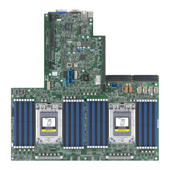
• If you have any questions, please contact our support team at: support@supermicro.com This manual may be periodically updated without notice. Please check the Supermicro website for possible updates to the manual revision level. - Page 9 Chapter 1: Introduction Figure 1-1. H12DSU-iN Motherboard Image Note: All graphics shown in this manual were based upon the latest PCB revision available at the time of publication of the manual. The motherboard you received may or may not look...
- Page 10 H12DSU-iN User's Manual H12DSU-iN REV: DESIGNED IN USA Figure 1-2. H12DSU-iN Motherboard Layout...
-
Page 11: Quick Reference
BMC_HB LED JNCSI1 SXB2 SXB3A SXB1B JWD1 SXB3B SXB1C JBT1 GPU PWR2-3 PSU2 PSU1 GPU PWR1 P2_NVME2/3 H12DSU-iN REV: DESIGNED IN USA JSD2 P1_NVME2/3 P2_NVME0 SATA10-13 JSD1 SXB3C USB3/4 (3.0) BP PWR1-4 P2_NVME1 SATA14-17 P1_NVME0/1 SATA0-7 SATA8 PWROK LED SATA9 USB2 (3.0) -
Page 12: Quick Reference Table
H12DSU-iN User's Manual Quick Reference Table Jumper Description Default Setting JBT1 CMOS Clear Open (Normal) JWD1 Watch Dog Pins 1-2 (Reset) Description Status UID_LED UID LED Solid Blue: UID Switch On Green: Blinking (BMC normal) BMC_HB LED BMC Heartbeat LED... -
Page 13: Motherboard Features
Chapter 1: Introduction Motherboard Features Motherboard Features • Dual EPYC 7002 series processor in SP3 sockets Memory • Up to 8TB of ECC DDR4 3200 MHz speed, RDIMM/LRDIMM/3DS/NVDIMM memory in thirty-two slots DIMM Size • Up to 256GB size at 1.2V Chipset •... - Page 14 H12DSU-iN User's Manual Motherboard Features Power Management • ACPI power management (S5) • Power button override mechanism • Power-on mode for AC power recovery System Health Monitoring • Onboard voltage monitoring for +3.3V, +3.3V Standby, +5V, +5V Standby, +12V, VBAT, Vcore, Vsoc, and Memory •...
- Page 15 Chapter 1: Introduction H12DSU-iN Front Rear IPMI LAN USB 3.0 x2 USB 3.0 x2 RJ45 CPU0 P1 [15:8] SXB3_1 RTL8211F SXB1_1 ASM1042 SXB2 NCSI DDR4 CPU0 USB2 [1_2] CPU0 P2 [15:0] AST2500 CPU0 P1 [4] BMC ROM SXB3_2 CPU1 P3 [15:0]...
-
Page 16: Processor And Chipset Overview
7nm process architecture, and is optimized for embedded storage solutions, networking applications, or cloud-computing platforms. With support of the new microarchitecture 7nm process technology, the H12DSU-iN drastically increases system performance for a multitude of server applications. -
Page 17: System Health Monitoring
Chapter 1: Introduction 1.4 System Health Monitoring This section describes the health monitoring features of the H12DSU-iN motherboard. The motherboard has an onboard chip that supports system health monitoring. Once a voltage becomes unstable, a warning is given or an error message is sent to the screen. The user can adjust the voltage thresholds to define the sensitivity of the voltage monitor. -
Page 18: Acpi Features
H12DSU-iN User's Manual 1.5 ACPI Features ACPI stands for Advanced Configuration and Power Interface. The ACPI specification defines a flexible and abstract hardware interface that provides a standard way to integrate power management features throughout a computer system including its hardware, operating system and application software. -
Page 19: Chapter 2 Installation
Chapter 2: Installation Chapter 2 Installation 2.1 Static-Sensitive Devices Electrostatic Discharge (ESD) can damage electronic com ponents. To prevent damage to your motherboard, it is important to handle it very carefully. The following measures are generally sufficient to protect your equipment from ESD. Precautions •... -
Page 20: Motherboard Installation
H12DSU-iN User's Manual 2.2 Motherboard Installation All motherboards have standard mounting holes to fit different types of chassis. Make sure that the locations of all the mounting holes for both the motherboard and the chassis match. Although a chassis may have both plastic and metal mounting fasteners, metal ones are highly recommended because they ground the motherboard to the chassis. - Page 21 Chapter 2: Installation Figure 2-1. Motherboard Mounting Holes...
-
Page 22: Installing The Motherboard
H12DSU-iN User's Manual Installing the Motherboard 1. Install the I/O shield into the back of the chassis. 2. Locate the mounting holes on the motherboard. See the previous page for the location. 3. Locate the matching mounting holes on the chassis. Align the mounting holes on the motherboard against the mounting holes on the chassis. -
Page 23: Processor And Heatsink Installation
CPU socket cap is in place and none of the socket pins are bent; otherwise, contact your retailer immediately. • Refer to the Supermicro website for updates on CPU support. Installing the Processor and Heatsink 1. Unscrew the screws holding down Force Frame in the sequence of 3-2-1. The screws are numbered on the Force Frame next to each screw hole. - Page 24 H12DSU-iN User's Manual 2. The spring-loaded Force Frame will raise up after the last screw securing it (#1) is removed. Gently allow it to lift up to its stopping position. 3. Lift the Rail Frame up by gripping the lift tabs near the front end of the rail frame. While keeping a secure grip of the Rail Frame, lift it to a position so you can do the next step of removing the External Cap.
- Page 25 Chapter 2: Installation 4. Remove the External Cap from the Rail Frame by pulling it upwards through the rail guides on the Rail Frame. External Cap PnP Cover Cap 5. The CPU Package is shipped from the factory with the Carrier Frame pre-assembled. Grip the handle of the Carrier Frame/CPU Package assembly from its shipping tray, and while gripping the handle, align the flanges of the Carrier Frame onto the rails of the Rail Frame so its pins will be at the bottom when the Rail Frame is lowered later.
- Page 26 H12DSU-iN User's Manual Note: You can only install the CPU inside the socket in one direction with the handle at the top. Make sure that it is properly inserted into the CPU socket before closing the Rail Frame plate. If it doesn't close properly, do not force it as it may damage your CPU. Instead, open the Rail Frame plate again, and double-check that the CPU is aligned properly.
- Page 27 Chapter 2: Installation 8. Gently lower the Rail Frame down onto the socket until the latches on the Rail Frame engage with the Socket housing. and it rests in place. DO NOT force it into place!
- Page 28 H12DSU-iN User's Manual 9. Gently lower the Force Frame down onto the Rail Frame and hold it in place until it is seated in the Socket housing. Note that the Force Frame is spring loaded and has to be held in place before it is secured. Important: Use a torque screwdriver, set it at 16.1 kgf-cm (14.0 lbf-in) with a Torx T20 screw head bit, to prevent damage to the CPU.
- Page 29 Chapter 2: Installation 11. After the Force Frame is secured and the CPU package is in place, now you must install the heatsink to the frame. Lower the heatsink down till it rests securely over the four screw holes on CPU Package on the socket frame. 12.
- Page 30 H12DSU-iN User's Manual Un-installing the Processor and Heatsink 1. Remove the heatsink attached to the top of the CPU Package by reversing the installation procedure. 2. Clean the Thermal grease left by the heatsink on the CPU package lid to limit the risk of it contaminating the CPU package land pads or contacts in the socket housing.
-
Page 31: Memory Support And Installation
Important: Exercise extreme care when installing or removing DIMM modules to prevent any possible damage. Memory Support The H12DSU-iN supports up to 8TB of ECC DDR4 3200 MHz speed, RDIMM/LRDIMM/3DS/ NVDIMM memory in thirty-two (32) slots. Refer to the table below for additional memory information. -
Page 32: Dimm Module Population Sequence
H12DSU-iN User's Manual DIMM Module Population Sequence When installing memory modules, the DIMM slots should be populated in the following order: DIMMA2, DIMMB2, DIMMC2, DIMMD2, DIMME2, DIMMF2, DIMMG2, DIMMH2, then DIMMA1, DIMMB1, DIMMC1, DIMMD1, DIMME1, DIMMF1, DIMMG1, DIMMH1. • The blue slots must be populated first. -
Page 33: Dimm Installation
Chapter 2: Installation DIMM Installation 1. Insert the desired number of DIMMs into the memory slots, starting with DIMMA2, DIMMB2, DIMMC2, DIMMD2, DIMME2, DIMMF2, DIMMG2, DIMMH2, then DIMMA1, DIMMB1, DIMMC1, DIMMD1, DIMME1, DIMMF1, DIMMG1, DIMMH1. For best performance, please use the memory modules of the same type and speed. -
Page 34: Rear I/O Ports
H12DSU-iN User's Manual 2.5 Rear I/O Ports See Figure 2-3 below for the locations and descriptions of the various I/O ports on the rear of the motherboard. H12DSU-iN REV: DESIGNED IN USA Figure 2-3. I/O Port Locations and Definitions Rear I/O Ports... - Page 35 Chapter 2: Installation Universal Serial Bus (USB) Ports There are two USB 3.0 ports (USB0/1) on the I/O back panel. The motherboard also provides two USB 3.0 connections via USB headers (USB3/4). The USB2 header is USB 3.0 Type A. The onboard headers can be used to provide front side USB access with a cable (not included).
- Page 36 H12DSU-iN User's Manual COM Port One COM port (COM1) is located on the I/O back panel. It can also serve as an Universal Asynchronous Receiver-Transmitter (UART) communication port. UID Switch/LED One UID Switch/LED is located on the I/O back panel. The UID indicators provide easy identification of a system or unit that in need or service.
-
Page 37: Front Control Panel
JF1 contains header pins for various buttons and indicators located on a control panel at the front of the chassis. This connector is designed specifically for use with Supermicro chassis. See the figure below for the descriptions of the front control panel buttons and LED indicators. - Page 38 H12DSU-iN User's Manual Power Switch The Power Switch connection is located on pins 1 and 2 of JF1. Attach it to a hardware power switch on the computer case to power on/off the system. To force the system to be powered off, press the button for at least 4 seconds.
- Page 39 Note: UID can also be triggered via IPMI on the serverboard. For more information on IPMI, please refer to the IPMI User's Guide posted on our website at http://www.supermicro.com. UID LED Pin Definitions (JF1)
- Page 40 H12DSU-iN User's Manual Power LED The Power LED connection is located on pins 15 and 16 of JF1. Attach a cable to Pin 15 and Pin 16 to show system power status. Refer to the table below for pin definitions.
-
Page 41: Connectors
Ground +12V Ground +12V Font Panel Connector (FP1) FP1 contains various buttons and indicators that are normally located on a control panel at the front of the chassis. The FP1 connector is designed specifically for use with the Supermicro chassis. -
Page 42: Headers
H12DSU-iN User's Manual Headers Fan Headers There are eight fan headers on the motherboard. These are 4-pin fan headers; pins 1-3 are backward compatible with traditional 3-pin fans. The onboard fan speeds are controlled by Fan Mode in the BMC. When using Fan Mode setting, please use all 4-pin fans. - Page 43 It enables the motherboard to deny access if the TPM associated with the hard drive is not installed in the system. Please go to the following link for more information on TPM: http://www.supermicro.com/ manuals/other/TPM.pdf. Trusted Platform Module Header...
- Page 44 Ground Clock 3.3V_Standby SATA Ports The H12DSU-iN has eighteen SATA 3.0 ports (SATA0-17) that are supported by the System on Chip chipset. NVM Express Connections Four NVM Express ports are located on the serverboard (two for each processor). These ports provide high-speed, low-latency PCI-E 4.0 x4 connections directly from the CPU to NVMe Solid State Drives (SSD).
-
Page 45: Jumper Settings
Chapter 2: Installation 2.8 Jumper Settings How Jumpers Work To modify the operation of the motherboard, jumpers can be used to choose between optional settings. Jumpers create shorts between two pins to change the function of the connector. Pin 1 is identified with a square solder pad on the printed circuit board. See the diagram below for an example of jumping pins 1 and 2. - Page 46 H12DSU-iN User's Manual Watch Dog JWD1 controls the Watch Dog function. Watch Dog is a monitor that can reboot the system when a software application hangs. Jumping pins 1-2 will cause Watch Dog to reset the system if an application hangs. Jumping pins 2-3 will generate a non-maskable interrupt (NMI) signal for the application that hangs.
-
Page 47: Led Indicators
Chapter 2: Installation 2.9 LED Indicators LAN Port LEDs The IPMI Ethernet port has two LED indicators. The Activity LED is yellow and indicates connection and activity. The Link LED may be green, amber, or off to indicate the speed of the connection. -
Page 48: Chapter 3 Troubleshooting
H12DSU-iN User's Manual Chapter 3 Troubleshooting 3.1 Troubleshooting Procedures Use the following procedures to troubleshoot your system. If you have followed all of the procedures below and still need assistance, refer to the ‘Technical Support Procedures’ and/ or ‘Returning Merchandise for Service’ section(s) in this chapter. Always disconnect the AC power cord before adding, changing or installing any non hot-swap hardware components. -
Page 49: No Video
Chapter 3: Troubleshooting 5. The CMOS battery on your motherboard may be old. Check to verify that it still supplies ~3V DC. If it does not, replace it with a new one. No Video 1. Check that the VGA cable is connected properly, and the monitor is on. 2. -
Page 50: What To Do If The System Is Losing The Setup Configuration
2. Memory support: Make sure that the memory modules are supported by testing the modules using memtest86 or a similar utility. Note: Refer to the product page on our website at http:\\www.supermicro.com for memory and CPU support and updates. 3. HDD support: Make sure that all hard disk drives (HDDs) work properly. Replace the bad HDDs with good ones. -
Page 51: Technical Support Procedures
Chapter 3: Troubleshooting 3. Using the minimum configuration for troubleshooting: Remove all unnecessary components (starting with add-on cards first), and use the minimum configuration (but with a CPU and a memory module installed) to identify the trouble areas. Refer to the steps listed in Section A above for proper troubleshooting procedures. -
Page 52: Frequently Asked Questions
3.3 Frequently Asked Questions Question: What type of memory does my motherboard support? Answer: The H12DSU-iN motherboard supports up to 8TB of ECC DDR4 3200 MHz speed, RDIMM/LRDIMM/3DS/NVDIMM memory in thirty-two (32) slots. See Section 2.4 for details on installing memory. - Page 53 Chapter 3: Troubleshooting Question: For the AMD EPYC platform, we found that the Windows Server 2012/2016 OS would not install properly. It however works fine with Linux OS, any suggestions? Answer: This issue is due to Windows server OS' compatibility with the virtualization function, we suggest to disable IOMMU (Input/Output Memory Management Unit) before installing the Windows Server OS.
- Page 54 H12DSU-iN User's Manual Question: Why did I fail to install Windows Server 2019 on a system with more than 255 logical processors? Answer: Follow the steps to solve the problem. 1. Disable SMT in BIOS. (BIOS >> Advanced >> CPU Configuration >> SMT Control >>...
- Page 55 Chapter 3: Troubleshooting Question: When I ran the executable file setup.exe to install the AMD SP3 I/O driver on Windows, the following message appeared: Answer: It happens in some environments. To solve this problem, click OK and save the installation package to the location you specify. The driver is then installed automatically.
-
Page 56: Returning Merchandise For Service
H12DSU-iN User's Manual 3.4 Returning Merchandise for Service A receipt or copy of your invoice marked with the date of purchase is required before any warranty service will be rendered. You can obtain service by calling your vendor for a Returned Merchandise Authorization (RMA) number. -
Page 57: Battery Installation
Chapter 3: Troubleshooting Battery Installation 1. To install an onboard battery, follow the steps 1 & 2 above and continue below: 2. Identify the battery's polarity. The positive (+) side should be facing up. 3. Insert the battery into the battery holder and push it down until you hear a click to ensure that the battery is securely locked. -
Page 58: Chapter 4 Uefi Bios
UEFI BIOS 4.1 Introduction This chapter describes the AMIBIOS™ Setup utility for the H12DSU-iN motherboard. The BIOS is stored on a chip and can be easily upgraded using a flash program. Note: Due to periodic changes to the BIOS, some settings may have been added or deleted and might not yet be recorded in this manual. -
Page 59: Main Setup
Note: The time is in the 24-hour format. For example, 5:30 P.M. appears as 17:30:00. The date's default value is 01/01/2015 after RTC reset. Supermicro H12DSU-iN BIOS Version This item displays the version of the BIOS ROM used in the system. - Page 60 H12DSU-iN User's Manual CPLD Version This item displays the CPLD version of the BIOS ROM used in the system. Memory Information Total Memory This item displays the total size of memory available in the system.
-
Page 61: Advanced
Chapter 4: UEFI BIOS 4.3 Advanced Use the arrow keys to select Boot Setup and press <Enter> to access the submenu items. Warning: Take caution when changing the Advanced settings. An incorrect value, a very high DRAM frequency, or an incorrect DRAM timing setting may make the system unstable. - Page 62 H12DSU-iN User's Manual Bootup NumLock State Use this feature to set the Power on state for the <Numlock> key. The options are On and Off. Wait For "F1" If Error Use this feature to force the system to wait until the 'F1' key is pressed if an error occurs.
- Page 63 Chapter 4: UEFI BIOS Trusted Computing Configuration Security Device Support If this feature and the TPM jumper on the motherboard are both set to Enabled, onboard security devices will be enabled for TPM (Trusted Platform Module) support to enhance data integrity and network security.
- Page 64 H12DSU-iN User's Manual Super IO Configuration The following Super IO information will display: • Super IO Chip AST2500 Serial Port 1 Configuration Serial Port Select Enabled to enable the selected onboard serial port. The options are Disabled and Enabled. Device Settings This item displays the status of a serial part specified by the user.
- Page 65 Chapter 4: UEFI BIOS *If the item above set to Enabled, the following items will become available for user's configuration: Console Redirection Settings Terminal Type This feature allows the user to select the target terminal emulation type for Console Redirection. Select VT100 to use the ASCII Character set. Select VT100+ to add color and function key support.
- Page 66 H12DSU-iN User's Manual VT-UTF8 Combo Key Support Select Enabled to enable VT-UTF8 Combination Key support for ANSI/VT100 terminals. The options are Disabled and Enabled. Recorder Mode Select Enabled to capture the data displayed on a terminal and send it as text messages to a remote server.
- Page 67 Chapter 4: UEFI BIOS Console Redirection Settings Terminal Type This feature allows the user to select the target terminal emulation type for Console Redirection. Select VT100 to use the ASCII Character set. Select VT100+ to add color and function key support. Select ANSI to use the Extended ASCII Character Set. Select VT-UTF8 to use UTF8 encoding to map Unicode characters into one or more bytes.
- Page 68 H12DSU-iN User's Manual Recorder Mode Select Enabled to capture the data displayed on a terminal and send it as text messages to a remote server. The options are Disabled and Enabled. Resolution 100x31 Select Enabled for extended-terminal resolution support. The options are Disabled and Enabled.
- Page 69 Chapter 4: UEFI BIOS Console Redirection Settings Out-of-Band Mgmt Port The feature selects a serial port in a client server to be used by the Microsoft Windows Emergency Management Services (EMS) to communicate with a remote host server. The options are COM1 and SOL.
- Page 70 H12DSU-iN User's Manual CPU Configuration SMT Control Use this setting to specify Simultaneous Multithreading. Options include Off for 1T single thread and Auto for 2T two-thread if your system is capable of it. Core Performance Boost This setting is used to configure for Core Performance Boost. Options include Disabled and Auto.
- Page 71 Chapter 4: UEFI BIOS • Processor Family • Processor Model • Microcode Patch Level • L1 Instruction Cache (Size/Method) • L1 Data Cache (Size/Method) • L2 Data Cache (Size/Method) • L3 Cache per Scoket (Size/Method) NB Configuration Determinism Control Use this setting to configure the Determinism Control.
- Page 72 H12DSU-iN User's Manual Memory Configuration Memory Clock This setting allows you to select different memory clock speed. Options include Auto and speed settings from 2666Mhz, 2933MHz to 3200MHz. Memory Interleaving This setting controls fabric level memory interleaving. Note that the channel, die and socket have requirements on memory populations and it will be ignored if the memory doesn't support the selected option.
- Page 73 Chapter 4: UEFI BIOS SR-IOV Support If the system has SR-IOV capable PCI-E devices, this setting will Enable or Disable the Single Root IO Virtualization Support for the system. BME DMA Mitigation Re-enable Bus Master Attribute disabled during Pci enumeration for PCI Bridges after SMM Locked.
- Page 74 H12DSU-iN User's Manual Onboard Video Option ROM This setting selects which onboard video firmware type to be selected. Options include Disabled, Legacy and EFI. Network Stack Confiuration Network Stack This setting allows you to Enable or Disable the UEFI Network Stack.
- Page 75 Chapter 4: UEFI BIOS XHCI Hand-off This is a work-around solution for operating systems that do not support XHCI (Extensible Host Controller Interface) hand-off. The XHCI ownership change should be claimed by the XHCI driver. The options include Enabled and Disabled. Port 60/64 Emulation Select Enabled for I/O port 60h/64h emulation support, which in turn, will provide complete legacy USB keyboard support for the operating systems that do not support legacy USB...
- Page 76 H12DSU-iN User's Manual Network Configuration iSCSI Configuration iSCSI Initiator Name This feature allows the user to enter the unique name of the iSCSI Initiator in IQN format. Once the name of the iSCSI Initiator is entered into the system, configure the proper settings for the following items.
- Page 77 Chapter 4: UEFI BIOS Discard Changes and Exit Use this feature to enroll to discard all changes and exit TLS settings. Delete Certification Use this feature to delete certification. RAM Disk Configuration Press <Enter> to add/remove RAM disks. Disk Memory Type Speficifies type of memory to use from available memory pool in system to create a disk.
-
Page 78: Ipmi
H12DSU-iN User's Manual 4.4 IPMI This tab allows you to configure the following IPMI settings for the system. Use this feature to configure Intelligent Platform Management Interface (IPMI) settings. BMC Firmware Revision This item indicates the IPMI firmware revision used in your system. - Page 79 Chapter 4: UEFI BIOS Erasing Settings Erase SEL Select Yes, On next reset to erase all system event logs upon next system reboot. Select Yes, On every reset to erase all system event logs upon each system reboot. Select No to keep all system event logs after each system reboot.
- Page 80 H12DSU-iN User's Manual Subnet Mask This item displays the sub-network that this computer belongs to. The value of each three- digit number separated by dots should not exceed 255. Station MAC Address This item displays the Station MAC address for this computer. Mac addresses are 6 two- digit hexadecimal numbers.
-
Page 81: Event Logs
Chapter 4: UEFI BIOS 4.5 Event Logs This tab allows the user to configure the following event logs settings for the system. Change SMBIOS Event Log Settings This feature allows the user to configure SMBIOS Event settings. Enabling/Disabling Options SMBIOS Event Log Select Enabled to enable SMBIOS (System Management BIOS) Event Logging during system boot. - Page 82 H12DSU-iN User's Manual When Log is Full Select Erase Immediately to immediately erase all errors in the SMBIOS event log when the event log is full. Select Do Nothing for the system to do nothing when the SMBIOS event log is full. The options are Do Nothing and Erase Immediately.
-
Page 83: Security
Chapter 4: UEFI BIOS 4.6 Security This tab allows you to configure the following security settings for the system. Administrator Password Press <Enter> to create a new, or change an existing Administrator password. Note that if the Administrator Password is erased, the User Password will be cleared as well. User Password Press Enter to create a new, or change an existing User password. - Page 84 H12DSU-iN User's Manual Secure Boot This option allows you specify when the Platform Key (PK) is enrolled. When enabled, the System Mode is user deployed, and the CSM function is disabled. Options include Disabled and Enabled. Secure Boot Mode Use this item to select the secure boot mode. The options are Standard and Custom.
- Page 85 Chapter 4: UEFI BIOS Restore DB defaults Select Yes to restore all DBs to the default settings. The options are Yes and No. Platform Key (PK) Details Select this feature to view the details of the Platform Key. Export Select Yes to export a PK from a file on an external media.
- Page 86 H12DSU-iN User's Manual Append Select Yes to add the db from the manufacturer's defaults list to the existing db. Select No to load the db from a file. The options are Yes and No. Delete Select Ok to remove the db and then the system will reset to Setup/Audit Mode.
- Page 87 Chapter 4: UEFI BIOS Set New Key Select Yes to load the DBT from the manufacturer's defaults. Select No to load the DBT from a file. The options are Yes and No. Append Key Select Yes to add the DBT from the manufacturer's defaults list to the existing DBT. Select No to load the DBT from a file.
-
Page 88: Boot
H12DSU-iN User's Manual 4.7 Boot Use this tab to configure Boot Settings: Boot Mode Select Use this item to select the type of device that the system is going to boot from. The options are Legacy, UEFI, and DUAL. The default setting is DUAL. - Page 89 Chapter 4: UEFI BIOS UEFI Application Boot Priorities This feature allows the user to specify which UEFI devices are boot devices. • Boot Option #1...
-
Page 90: Save & Exit
H12DSU-iN User's Manual 4.8 Save & Exit Select the Save & Exit tab to enter the Save & Exit BIOS Setup screen. Discard Changes and Exit Select this option to quit the BIOS Setup without making any permanent changes to the system configuration, and reboot the computer. - Page 91 Chapter 4: UEFI BIOS Default Options Restore Defaults To set this feature, select Restore Defaults from the Save & Exit menu and press <Enter>. These are factory settings designed for maximum system stability, but not for maximum performance. Save as User Defaults To set this feature, select Save as User Defaults from the Exit menu and press <Enter>.
-
Page 92: Appendix A Software
USB/SATA DVD drive, or a USB flash drive, or the IPMI KVM console. 2. Retrieve the proper RST/RSTe driver. Go to the Supermicro web page for your motherboard and click on "Download the Latest Drivers and Utilities", select the proper driver, and copy it to a USB flash drive. - Page 93 Appendix A: Software 4. During Windows Setup, continue to the dialog where you select the drives on which to install Windows. If the disk you want to use is not listed, click on “Load driver” link at the bottom left corner. Figure A-2.
-
Page 94: Driver Installation
The Supermicro website contains drivers and utilities for your system at https://www. supermicro.com/wftp/driver. Some of these must be installed, such as the chipset driver. After accessing the website, go into the CDR_Images (in the parent directory of the above link) and locate the ISO file for your motherboard. Download this file to to a USB flash drive or a DVD. -
Page 95: Superdoctor ® 5
A.3 SuperDoctor ® The Supermicro SuperDoctor 5 is a program that functions in a command-line or web-based interface for Windows and Linux operating systems. The program monitors such system health information as CPU temperature, system voltages, system power consumption, fan speed, and provides alerts via email or Simple Network Management Protocol (SNMP). -
Page 96: Appendix B Standardized Warning Statements
The following statements are industry standard warnings, provided to warn the user of situations which have the potential for bodily injury. Should you have questions or experience difficulty, contact Supermicro's Technical Support department for assistance. Only certified technicians should attempt to install or configure components. - Page 97 Appendix B: Warning Statements Attention Danger d'explosion si la pile n'est pas remplacée correctement. Ne la remplacer que par une pile de type semblable ou équivalent, recommandée par le fabricant. Jeter les piles usagées conformément aux instructions du fabricant. ¡Advertencia! Existe peligro de explosión si la batería se reemplaza de manera incorrecta.
-
Page 98: Product Disposal
H12DSU-iN User's Manual B.2 Product Disposal Warning! Ultimate disposal of this product should be handled according to all national laws and regulations. 製品の廃棄 この製品を廃棄処分する場合、 国の関係する全ての法律 ・ 条例に従い処理する必要があります。 警告 本产品的废弃处理应根据所有国家的法律和规章进行。 警告 本產品的廢棄處理應根據所有國家的法律和規章進行。 Warnung Die Entsorgung dieses Produkts sollte gemäß allen Bestimmungen und Gesetzen des Landes erfolgen. -
Page 99: Appendix C Uefi Bios Recovery
Warning: Do not upgrade the BIOS unless your system has a BIOS-related issue. Flashing the wrong BIOS can cause irreparable damage to the system. In no event shall Supermicro be liable for direct, indirect, special, incidental, or consequential damages arising from a BIOS update. - Page 100 USB flash drive with FAT16 or FAT32 format and rename the file to SUPER.ROM. Note: If you cannot locate the "SUPER.ROM" file in your driver disk, visit our website at www.supermicro.com to download the correct BIOS image into a USB flash device and rename it "SUPER.ROM".
- Page 101 SUPERMICO BIOS Update: https://www.youtube.com/watch?v=S8z6iOEHGwY * If the BIOS flash recovery fails, contact our RMA Department to have the BIOS chip reprogrammed. This will require shipping the board to Supermicro for repair. Submit your RMA request at https://www.supermicro.com/support/rma Please make sure to follow all instructions when returning the motherboard.
Need help?
Do you have a question about the H12DSU-iN and is the answer not in the manual?
Questions and answers